manuals.online logo
Brands
  1. Home
  2. •
  3. Brands
  4. •
  5. Pilz
  6. •
  7. Switch
  8. •
  9. Pilz PSEN ma1.3p-22 User manual

Pilz PSEN ma1.3p-22 User manual

22 148-01
PSEN ma1.3p-22
- 1 -
4D Betriebsanleitung
4GB Operating instructions
4F Manuel d'utilisation
22 148-01PSEN ma1.3p-22
Sicherheitsschalter PSEN ma1.3p-22
529551755
Der Sicherheitsschalter erfüllt Forderungen der
EN 60204-1.
Der Sicherheitsschalter erfüllt EN 60947-5-3
nur zusammen mit der Schnittstelle PSEN ix1,
dem Betätiger PSEN ma1.3-08 bzw. PSEN
ma1.3-12 und hierfür zugelassenen Auswerte-
geräten.
Schließen Sie den Sicherheitsschalter nur an
Auswertegeräte an, die im Abschnitt "An-
schlüsse" aufgeführt sind.
Safety switch PSEN ma1.3p-22
The safety switch meets the requirements of
EN 60204-1.
The safety switch only complies with
EN 60947-5-3 in conjunction with the PSEN ix1
interface, the actuator PSEN ma1.3-08 /
PSEN ma1.3-12 and its approved evaluation
devices.
The safety switch should only be connected to
the evaluation devices listed under "Connec-
tions".
Capteur de sécurité PSEN ma1.3p-22
Le capteur de sécurité satisfait aux exigences
de l'EN 60204-1.
Le capteur de sécurité est conforme à la norme
EN 60947-5-3 uniquement lorsqu'il est utilisé
avec l'interface PSEN ix1, l'actionneur
PSEN ma1.3-08 ou PSEN ma1.3-12 et les ap-
pareils de contrôle spécialement homologués à
cet effet.
Ne raccordez le capteur de sécurité qu'aux uni-
tés de contrôle indiquées dans le chapitre
« Raccordements ».
Zu ihrer Sicherheit
547263243
`Installieren und nehmen Sie das Gerät nur
dann in Betrieb, wenn Sie diese Betriebsan-
leitung gelesen und verstanden haben und
Sie mit den geltenden Vorschriften über Ar-
beitssicherheit und Unfallverhütung vertraut
sind.
Beachten Sie die VDE- sowie die örtlichen
Vorschriften, insbesondere hinsichtlich
Schutzmaßnahmen
`Durch Öffnen des Gehäuses oder eigen-
mächtige Umbauten erlischt jegliche Ge-
währleistung.
For your safety
`Only install and commission the unit if you
have read and understood these operating
instructions and are familiar with the applica-
ble regulations for health and safety at work
and accident prevention.
Ensure VDE and local regulations are met,
especially those relating to safety.
`Any guarantee is rendered invalid if the hous-
ing is opened or unauthorised modifications
are carried out.
Pour votre sécurité
`Vous n'installerez l'appareil et ne le mettrez
en service qu'après avoir lu et compris le
présent manuel d'utilisation et vous être fa-
miliarisé avec les prescriptions en vigueur
sur la sécurité du travail et la prévention des
accidents.
Respectez les normes locales ou VDE, parti-
culièrement en ce qui concerne la sécurité.
`L'ouverture de l'appareil ou sa modification
annule automatiquement la garantie.
Gerätemerkmale
1091646731
`Zum Sicherheitsschalter gehört der Betätiger
PSEN ma1.3-08 oder PSEN ma1.3-12
1140433803
`Sicherheitsschalter mit M8/8-pol. Stecker
510237579
`2 Sicherheitskontakte (Schließer)
1091653387
`1 Hilfskontakt (Schließer)
1091670795
`Betätiger PSEN ma1.3-08:
– Gesicherter Schaltabstand: 8 mm
– Gesicherter Ausschaltabstand: 15 mm
`Betätiger PSEN ma1.3-12:
– Gesicherter Schaltabstand: 12 mm
– Gesicherter Ausschaltabstand: 25 mm
808101259
`Sicherheitsschalter und Betätiger mit runder
Bauform M12
oder
`Sicherheitsschalter mit runder Bauform M12,
Betätiger mit quadratischer Bauform (ver-
schiedene Betätigungsrichtungen möglich)
510321547
`Wirkweise magnetisch
510477451
`Schaltspannung 24 V DC
702773515
`Reihenschaltung über Schnittstelle PSEN ix1
763865611
`LED zur Anzeige des Schaltzustands
Unit features
`The safety switch is used with the actuator
PSEN ma1.3-08 or PSEN ma1.3-12
`Safety switch with M8/8-pin connector
`2 safety contacts (N/O)
`1 auxiliary contact (N/O)
`Actuator PSEN ma1.3-08:
– Assured operating distance: 8 mm
– Assured release distance: 15 mm
`Actuator PSEN ma1.3-12:
– Assured operating distance: 12 mm
– Assured release distance: 25 mm
`Safety switch and actuator with M12 round
design
or
`Safety switch with M12 round design, actua-
tor with square design (various directions of
actuation are possible)
`Works magnetically
`Switching voltage 24 VDC
`Series connection via PSEN ix1 interface
`LED to display switch status
Caractéristiques de l'appareil
`L'actionneur PSEN ma1.3-08 ou PSEN
ma1.3-12 est associé au capteur de sécuri-
té.
`Capteur de sécurité avec connecteur M8 à 8
broches
`2 contacts de sécurité (contacts à fermeture)
`1 contact d'information (contact à fermeture)
`Actionneur PSEN ma1.3-08 :
– Distance de commutation de sécurité :
8 mm
– Distance de déclenchement de
sécurité :15 mm
`Actionneur PSEN ma1.3-12 :
– Distance de commutation de sécurité :
12 mm
– Distance de déclenchement de
sécurité : 25 mm
`Capteurs de sécurité et actionneurs avec
une architecture arrondie M12
ou
`Capteurs de sécurité avec une architecture
arrondie M12, actionneurs avec architecture
carrée (différents sens de manœuvre possi-
bles)
`actionnement magnétique
`tension commutée 24 V DC
`Montage en série par l'intermédiaire de l'in-
terface PSEN ix1
`LED pour l'affichage de l'état de commuta-
tion
- 2 -
Schaltabstände Operating distances Distances de commutation
Betätiger PSEN ma1.3-08 Actuator PSEN ma1.3-08 Actionneur PSEN ma1.3-08
Betätiger PSEN ma1.3-12 Actuator PSEN ma1.3-12 Actionneur PSEN ma1.3-12
Seiten- und Höhenversatz Lateral and vertical offset Décalage latéral et en hauteur
Betätiger PSEN ma1.3-08
803367563
`Gesicherter Schaltabstand Sao in mm:
`Gesicherter Ausschaltabstand Sar:
Max. 15 mm bei allen Höhen- und Seiten-
versätzen
Actuator PSEN ma1.3-08
`Assured operating distance Sao in mm:
`Assured release distance Sar:
Max. 15 mm with all vertical and lateral off-
sets
Actionneur PSEN ma1.3-08
`Distance de commutation de sécurité Sao en
mm :
`Distance de coupure de sécurité Sar :
15 mm maximum pour tous les décalages
latéraux et en hauteur
Betätiger PSEN ma1.3-12
1044323979
`Gesicherter Schaltabstand Sao in mm:
`Gesicherter Ausschaltabstand Sar:
Max. 25 mm bei allen Höhen- und Seiten-
versätzen
`Negativer Höhenversatz nicht zugelassen
Die angegebenen Werte sind gültig bei einer
Temperatur von 20°C.
Actuator PSEN ma1.3-12
`Assured operating distance Sao in mm:
`Assured release distance Sar:
Max. 25 mm with all vertical and lateral off-
sets
`A negative vertical offset is not permitted
The stated values are valid at a temperature of
20°C.
Actionneur PSEN ma1.3-12
`Distance de commutation de sécurité Sao en
mm :
`Distance de coupure de sécurité Sar :
25 mm maximum pour tous les décalages
latéraux et en hauteur
`Le décalage négatif en hauteur n'est pas
autorisé
Les valeurs indiquées sont valables pour une
température de 20 °C.
Seitenversatz/Lateral offset/
Décalage latéral Höhenversatz/Height offset/
Décalage en hauteur Schaltabstand/
Operating distance/
Portee de travail
sao =
sar = 15
Ein/On/Marche
Aus/Off/Arrêt
Ansprechfläche/Sensing face/Surface d'activation
Seitenversatz/Lateral offset/
Décalage latéral Schaltabstand/
Operating distance/
Portee de travail
sao = 12
sar = 25
Ein/On/Marche
Aus/Off/Arrêt
Höhenversatz/Height offset/
Décalage en hauteur
Ansprechfläche/Sensing face/Surface d'activation
2
0
4
420
5,57,08,0
4,06,07,0
3,05,06,0
Höhenversatz/Height offset/
Décalage en hauteur
Seitenversatz/Lateral
offset/Décalage latéral
2
0
4
420
5,57,08,0
4,06,07,0
3,05,06,0
Höhenversatz/Height offset/
Décalage en hauteur
Seitenversatz/Lateral
offset/Décalage latéral
2
0
4
420
5,57,08,0
4,06,07,0
3,05,06,0
Höhenversatz/Height offset/
Décalage en hauteur
Seitenversatz/Lateral
offset/Décalage latéral
2
0
4
210
8,010,0
12,0
7,5
9,5
Höhenversatz/Height offset/
Décalage en hauteur
Seitenversatz/Lateral
offset/Décalage latéral
6
8,010,0
12,0
11,0
6,58,5
10,0
2
0
4
210
8,010,0
12,0
7,5
9,5
Höhenversatz/Height offset/
Décalage en hauteur
Seitenversatz/Lateral
offset/Décalage latéral
6
8,010,0
12,0
11,0
6,58,5
10,0
2
0
4
210
8,010,0
12,0
7,5
9,5
Höhenversatz/Height offset/
Décalage en hauteur
Seitenversatz/Lateral
offset/Décalage latéral
6
8,010,0
12,0
11,0
6,58,5
10,0
- 3 -
Höhenversatz negativ/positiv Negative/positive vertical offset Décalage en hauteur négatif / positif
Verdrahtung
492354955
Beachten Sie:
`Angaben im Abschnitt „Technische Daten“
unbedingt einhalten.
`Berechnung der max. Leitungslänge Imax im
Eingangskreis:
Rlmax = max. Gesamtleitungswiderstand
(s. techn. Daten)
Rl/ km = Leitungswiderstand/km
`Beachten Sie bei Einsatz von Auswertegerä-
ten mit rückfallverzögerten Kontakten:
– Verzögerungszeit ≤30 s: die rückfallverzö-
gerten Kontakte genügen den Anforderun-
gen der Kategorie 3 gemäß EN 954-1 bzw.
den Anforderungen an PDF mit Einfehlersi-
cherheit (PDF-S).
– Verzögerungszeit ≥30 s: die rückfallverzö-
gerten Kontakte genügen den Anforderun-
gen der Kategorie 1 gemäß EN 954-1 bzw.
den Anforderungen an PDF mit Zuverläs-
sigkeit durch besonderes Design (PDF-D).
`Überprüfen Sie in folgenden Fällen von Inbe-
triebnahme die Funktion Querschlusserken-
nung:
– Bei Auswertegeräten mit Versorgungs-
spannung DC: Gesamtleitungswiderstand
≥15 Ohm pro Kanal
– Bei Auswertegeräten mit Versorgungs-
spannung AC: Gesamtleitungswiderstand
≥25 Ohm pro Kanal
– Wie Sie die Querschlussprüfung durchfüh-
ren müssen, entnehmen Sie der entspre-
chenden Bedienungsanleitung des
Auswertegeräts.
Wiring
Please note:
`Information given in the “Technical details”
must be followed.
`Calculation of the max. cable runs lmax in the
input circuit:
Rlmax = max. overall cable resistance (see
Technical details)
Rl/ km = cable resistance/km
`When using evaluation devices with delay-on
de-energisation contacts, please note:
– Delay time ≤30 s: Delay-on de-energisation
contacts satisfy the requirements of cate-
gory 3 in accordance with EN 954-1 and
the requirements of a PDF with single-fault
tolerance (PDF-S).
– Delay time ≥30 s: Delay-on de-energisa-
tion contacts satisfy the requirements of
Category 1 in accordance with EN 954-1
and the requirements of a PDF with de-
signed reliability (PDF-D).
`In the following commissioning cases, check
the function that detects shorts across con-
tacts:
– On evaluation devices with DC supply
voltage: Overall cable resistance ≥15
Ohms per channel
– On evaluation devices with AC supply volt-
age: Overall cable resistance ≥25 Ohms
per channel
– For details of how to perform the test for
shorts across the contacts, please refer to
the operating manual for the relevant eval-
uation device.
Câblage
Important :
`Tenez compte impérativement des données
indiquées au chapitre "Caractéristiques
techniques".
`Calcul de la longueur de câble max. Imax sur
le circuit d'entrée :
Rlmax = résistance max. de l'ensemble du
câblage (voir les caractéristiques techni-
ques)
Rl/km = résistance du câblage/km
`En cas de mise en œuvre d'appareils de con-
trôle avec contacts temporisés à la retom-
bée, il faut tenir compte des indications
suivantes :
–Temporisation≤30 s : les contacts tempo-
risés à la retombée satisfont aux prescrip-
tions de la catégorie 3 selon l'EN 954-1, et/
ou aux prescriptions des PDF avec sécuri-
té de défaut unique (PDF-S).
–Temporisation≥30 s : les contacts tempo-
risés à la retombée satisfont aux prescrip-
tions de la catégorie 1 selon l'EN 954-1, et/
ou aux prescriptions des PDF avec une
fiabilité obtenue grâce à un design particu-
lier (PDF-D).
`Vérifiez dans les cas suivants de mise en ser-
vice la fonction de détection des courts-
circuits :
– pour les appareils de contrôle avec ali-
mentation DC : Résistance de l'ensemble
du câblage ≥15 ohms par canal
– pour les appareils de contrôle avec ali-
mentation AC : Résistance de l'ensemble
du câblage ≥25 ohms par canal
– vous trouverez dans la notice d'utilisation
de l'appareil de contrôle comment exécu-
ter le contrôle des courts-circuits.
-2 210-1
-+
Rlmax
Rl / km
Imax = Rlmax
Rl / km
Imax = Rlmax
Rl / km
Imax =
- 4 -
Anschlüsse Connections Raccordements
Anschlussbelegung Terminal assignment Affectation des broches
777658251
WICHTIG
Die Farbkennzeichnung für die Anschlus-
sleitung gilt nur für die als Zubehör erhältli-
chen Kabel von Pilz.
Der Sicherheitsschalter ist in unbetätigtem Zu-
stand dargestellt.
NOTICE
The colour marking for the connection lead
only applies for the cable that Pilz supplies
as an accessory.
The safety switch is shown in an unoperated
condition.
IMPORTANT
Le marquage de couleur du câble de rac-
cordement est uniquement valable pour les
câbles Pilz disponibles en tant qu'acces-
soires.
Le capteur de sécurité est représenté en posi-
tion de repos.
Belegung des 8-pol. M8-Stiftsteckers/Assign-
ment of the 8-pin M8 male connector/Repéra-
ge du connecteur mâle M8 à 8 pôles
807945483
WICHTIG
Der Hilfskontakt mit LED
`darf mit PNOZ X-Geräten nur mit Versor-
gungsspannung bis 24 V DC betrieben
werden
`ist mit PNOZ X-, PNOZelog- und
PNOZmulti-Geräten nicht in Reihe
schaltbar
NOTICE
The auxiliary contact with LED
`May only be operated with a supply volt-
age up to 24 VDC on PNOZ X units
`May not be connected in series with
PNOZ X, PNOZelog and PNOZmulti
units
IMPORTANT
Le contact d'information avec LED
`ne doit être utilisé, pour les appareils
PNOZ X, qu'avec une alimentation jus-
qu'à 24 V DC
`ne peut pas être monté en série avec les
appareils PNOZ X, PNOZelog et
PNOZmulti
12
3
4
5
6
7
weiß/white/blanc
braun/brown/marron
blau/blue/bleu
gelb/yellow/ambre
rot/red/rouge
grün/green/vert
6
3
1
4
2+
7
NC
NC
5
grau/grey/gris
rosa/pink/rose
- 5 -
Anschluss an Auswertegeräte Connection to evaluation devices Raccordement aux appareils de contrôle
785477899
Der Hilfskontakt mit LED kann als Meldeaus-
gang verwendet werden (siehe technische Da-
ten)
The auxiliary contact with LED may be used as
a signal output (see Technical details)
Le contact d'information avec LED peut être
utilisé comme sortie d'information (voir les ca-
ractéristiques techniques)
`Anschluss Hilfskontakt mit LED `Auxiliary contact with LED connection `Raccordement du contact d'information
avec LED
PNOZ X, PNOZpower, PNOZsigma, PNOZelog PNOZmulti, PSS, PSSu
`Anschluss an PNOZ X, PNOZpower, PNOZ-
sigma, PNOZelog
`Connection to PNOZ X, PNOZpower,
PNOZsigma, PNOZelog
`Raccordement aux PNOZ X, PNOZpower,
PNOZsigma, PNOZelog
GND
1
2
3
4
5
6
7
A1/+24 V braun/brown/marron
blau/blue/bleu
A1/+24 V
I7
1
2
3
4
5
6
7
braun/brown/marron
blau/blue/bleu
PNOZ p1p
PNOZ p1vp
PNOZ X2/X2P
PNOZ X2.1
(nur 24 V DC/
24 V DC onl /
24 V DC seulement)
PNOZ X2.3P
PNOZ X2.7P
PNOZ X2.8P
PNOZ X2C
PNOZ X2.1C
(nur 24 V DC/
24 V DC onl /
24 V DC seulement)
PNOZ X4/X8P
PNOZ X9
PNOZ X10/X10.1
PNOZ X10.11
PNOZ Ex
PNOZ e1p
PNOZ e1.1p
PNOZ e1vp
PNOZ e6.1p
PNOZ e6vp
PNOZ s3
PNOZ s4
PNOZ s5 rosa/pink/rose
S21
S22
1
2
3
4
5
6
7
S11
S12
11
12
13
14
1
2
3
4
PSEN ix1 weiß/white/blanc
gelb/yellow/jaune
grün/green/vert
PNOZ X2.9P
rosa/pink/rose
S11
S52
1
2
3
4
5
6
7
S11
S12
11
12
13
14
1
2
3
4
PSEN ix1 weiß/white/blanc
gelb/yellow/jaune
grün/green/vert
PNOZ X5
PNOZ X5J
rosa/pink/rose
S11
S22
1
2
3
4
5
6
7
S11
S12
11
12
13
14
1
2
3
4
PSEN ix1 weiß/white/blanc
gelb/yellow/jaune
grün/green/vert
PNOZ 11
PNOZ 16
PNOZ X11P
PNOZ X13
PNOZ X3.1
PNOZ X3P
PNOZ X2.5P
PNOZ X3
PNOZ X3.10P
PNOZ XV2
PNOZ XV2P
PNOZ XV3
PNOZ XV3P rosa/pink/rose
S21
S22
1
2
3
4
5
6
7
S31
S32
11
12
13
14
1
2
3
4
PSEN ix1 weiß/white/blanc
gelb/yellow/jaune
grün/green/vert
- 6 -
`Anschluss an PNOZmulti, PSS, PSSu `Connection to PNOZmulti, PSS, PSSu `Raccordement au PNOZmulti, PSS, PSSu
PNOZ X6 (mit Brücke/with li k/avec po tage Y3-Y4)PNOZ X6 (mit Brücke/with li k/avec po tage Y3-Y4)
rosa/pink/rose
S23
S24
1
2
3
4
5
6
7
S11
S12
11
12
13
14
1
2
3
4
PSEN ix1 weiß/white/blanc
gelb/yellow/jaune
grün/green/vert
PMUT X1P
rosa/pink/rose
S61
S62
1
2
3
4
5
6
7
S51
S52
11
12
13
14
1
2
3
4
PSEN ix1 weiß/white/blanc
gelb/yellow/jaune
grün/green/vert
PNOZ e5.11p
rosa/pink/rose
A1
S32
1
2
3
4
5
6
7
A1
S42
11
12
13
14
1
2
3
4
PSEN ix1 weiß/white/blanc
gelb/yellow/jaune
grün/green/vert
Schutztür/safety gate/protecteur mobile
Schaltertyp 3/switchtype 3/type du capteure 3
I0, I1: Ei gä ge/i puts/e trées
T0, T1: Taktausgä ge/test pulse outputs/sorties
impulsio elles rosa/pink/rose
T0
I0
1
2
3
4
5
6
7
T1
I1
11
12
13
14
1
2
3
4
PSEN ix1 weiß/white/blanc
gelb/yellow/jaune
grün/green/vert
- 7 -
Montage Installation Montage
796864011
`Berücksichtigen Sie bei der Montage die An-
forderungen der DIN EN 1088
`Sicherheitsschalter und Betätiger möglichst
nicht auf ferromagnetisches Material montie-
ren. Es sind Änderungen der Schaltabstände
zu erwarten.
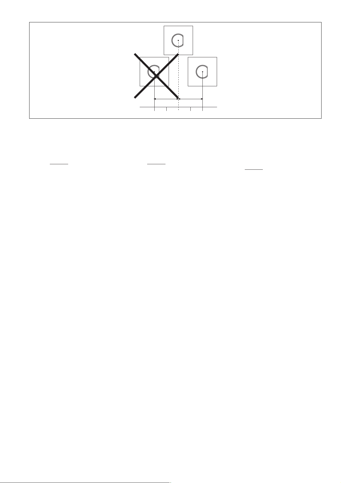
`Der Abstand zwischen zwei Systemen aus
Sicherheitschalter und Betätiger muss bei
– Betätiger PSEN ma1.3-08
mindestens 25 mm betragen und
– Betätiger PSEN ma1.3-12
mindestens 35 mm betragen.
`Sicherheitsschalter und Betätiger
– von Eisenspänen fernhalten
– keinen starken Magnetfeldern aussetzen
– keinen starken Stößen oder Schwingun-
gen aussetzen
– nicht als Anschlag benutzen
– nur für feste Verkabelung
Montage mit Betätiger PSEN ma1.3-08:
`Die Montagelage ist beliebig. Sicherheits-
schalter und Betätiger müssen so montiert
werden, dass die abgeschrägten Flächen ge-
nau gegenüberliegen.
`Befestigen Sie Sicherheitsschalter und Betä-
tiger ausschließlich mit Muttern M12 aus
nicht magnetischem Material (z. B. Messing).
Anzugsdrehmoment max. 300 Ncm.
Montage mit Betätiger PSEN ma1.3-12:
`Befestigen Sie den Betätiger mit dem mitge-
lieferten Halter. Die Ansprechfläche am Betä-
tiger ist durch einen Kreis mit abgeschrägter
Fläche in Form des Sicherheitsschalters ge-
kennzeichnet.
Die Ansprechfläche kann je nach Betäti-
gungsrichtung in 3 Richtungen ausgerichtet
werden.
`Die Montagelage ist beliebig. Sicherheits-
schalter und Betätiger müssen so montiert
werden, dass die abgeschrägte Fläche des
Sicherheitsschalters der aufgedruckten ab-
geschrägten Fläche am Betätiger genau ge-
genüberliegt.
`Befestigen Sie den Halter ausschließlich mit
Schrauben aus nicht magnetischem Materi-
al.
`Schieben Sie den Betätiger in der gewünsch-
ten Betätigungsrichtung in den Halter ein, bis
der Betätiger einrastet. Befestigen Sie den
Betätiger mit einer Madenschraube M3 x 6
mm: DIN 319 (im Lieferumfang enthalten).
Anzugsdrehmoment max. 10 Ncm.
`When installing make sure you comply with
the requirements of DIN EN 1088
`If possible, do not install the safety switch
and actuator on to ferromagnetic material.
Changes to the operating distances are to be
expected.
`The distance between two systems compris-
ing safety switch and actuator must be
– At least 25 mm on the actuator
PSEN ma1.3-08
and
– At least 35 mm on the actuator
PSEN ma1.3-12
.
`Safety switches and actuators
– Should be kept away from iron swarf
– Should not be exposed to strong magnetic
fields
– Should not be exposed to heavy shock or
vibration
– Should not be used as a limit stop
– Should be used for fixed wiring only
Installation with actuator PSEN ma1.3-08:
`The unit can be installed in any position. The
safety switch and actuator must be installed
so that the bevelled surfaces face each other
precisely.
`The safety switch and actuator should only
be secured using M12 nuts made of non-
magnetic material (e.g. brass). Torque set-
ting max. 300 Ncm.
Installation with actuator PSEN ma1.3-12:
`Attach the actuator using the bracket sup-
plied. The sensing face on the actuator is
marked by a circle with a bevelled surface in
the shape of the safety switch.
The sensing face can be aligned in 3 direc-
tions, depending on the direction of actua-
tion.
`The unit can be installed in any position.
Safety switches and actuators must be in-
stalled so that the bevelled surface on the
safety switch and the embossed bevelled
surface on the actuator face each other pre-
cisely.
`The bracket should only be secured using
screws made of non-magnetic material.
`Slide the actuator on to the bracket in the re-
quired direction of actuation until the actua-
tor clicks into place. The actuator should be
secured using a set screw M3 x 6 mm: DIN
319 (supplied with the unit). Torque setting
max. 10 Ncm.
`Veuillez tenir compte lors du montage des
exigences de la normes DIN EN 1088.
`Evitez d'installer le capteur de sécurité et
l'actionneur sur du matériel ferromagnétique.
Les distances de commutation peuvent être
modifiées.
`La distance entre deux systèmes composés
d'un capteur de sécurité et d'un actionneur
doit être
– pour l'actionneur PSEN ma1.3-08
d'au moins 25 mm et
– pour l'actionneur PSEN ma1.3-12
d'au moins 35 mm.
`Le capteur de sécurité et l'actionneur
– doivent être éloignés des copeaux métalli-
ques
– ne doivent pas être exposés à des champs
magnétiques élevés
– ne doivent pas subir des chocs et vibra-
tions importants
– ne doivent pas être utilisés comme butée
– ne doivent être utilisés que dans un câbla-
ge fixe
Montage avec l'actionneur PSEN ma1.3-08 :
`Le sens de montage n'a pas d'importance.
Cependant, le capteur de sécurité et l'action-
neur doivent être montés de telle manière
que les surfaces biseautées soient exacte-
ment en face l'une de l'autre.
`Fixez le capteur de sécurité et l'actionneur
exclusivement à l'aide d'un écrou M12 dans
des matériaux non magnétiques (par
exemple : en laiton). Couple de serrage max.
300 Ncm.
Montage avec l'actionneur PSEN ma1.3-12 :
`Fixez l'actionneur à l'aide du support fourni à
la livraison. La surface d'activation sur l'ac-
tionneur est marquée par un cercle à la sur-
face biseautée, dans la forme du capteur de
sécurité.
Suivant le sens de manœuvre, la surface
d'activation peut être orientée dans 3 direc-
tions différentes.
`Le sens de montage n'a pas d'importance.
Cependant, le capteur de sécurité et l'action-
neur doivent être montés de telle manière
que la surface biseautée du capteur de sécu-
rité soient exactement en face de la surface
biseautée imprimée de l'actionneur.
`Le support doit uniquement être fixé à l'aide
de vis en matériau non magnétique.
`Faites glisser l'actionneur dans le support
suivant dans le sens de manœuvre souhaité
jusqu'à l'enclenchement de l'actionneur.
Fixez l'actionneur à l'aide d'une vis sans tête
M3 x 6 mm : DIN 319 (fournie à la livraison).
Couple de serrage max. 10 Ncm.
Ansprech läche
Sensing ace
Sur ace activation Ansprech läche
Sensing ace
Sur ace activation
Ansprech läche
Sensing ace
Sur ace activation
- 8 -
Justage
699948299
`Der Sicherheitsschalter darf nur mit dem zu-
gehörigen Betätiger PSEN ma1.3-08 oder
PSEN ma1.3-12 verwendet werden.
`Prüfen Sie die Funktion immer mit der
Schnittstelle PSEN ix1 und einem der zuge-
lassenen Auswertegeräte.
`Die angegebenen Schaltabstände (siehe
technische Daten) gelten nur, wenn Sicher-
heitsschalter und Betätiger parallel gegen-
überliegend montiert sind. Andere
Anordnungen können zu abweichenden
Schaltabständen führen. Beachten Sie den
maximal zulässigen Seiten- und Höhenver-
satz (siehe "Schaltabstände" und "Max. Sei-
ten- und Höhenversatz").
Adjustment
`The safety switch may only be used with the
corresponding actuator PSEN ma1.3-08 or
PSEN ma1.3-12.
`Always test the function with the PSEN ix1
interface and one of the approved evaluation
devices.
`The stated operating distances (see Techni-
cal details) only apply when the safety switch
and actuator are installed facing each other
in parallel. Operating distances may deviate
if other arrangements are used. Note the
maximum permitted lateral and vertical off-
set (see "Switching distances" and "Max. lat-
eral and vertical offset").
Ajustage
`Le capteur de sécurité doit être utilisé uni-
quement avec l'actionneur correspondant
PSEN ma1.3-08 ou PSEN ma1.3-12.
`Vérifiez toujours la fonction uniquement avec
l'interface PSEN ix1 et l'un des appareils de
contrôle homologués.
`Les distances de commutation mentionnées
dans les caractéristiques techniques sont
valables uniquement lorsque le capteur de
sécurité et l'actionneur sont montés l'un en
face de l'autre de manière parallèle. D'autres
montages peuvent conduire à des distances
de commutation divergentes. Respectez le
décalage latéral et en hauteur maximal auto-
risé (voir « Distances de commutation » et
« Décalage latéral et en hauteur maximum »).
Abmessungen in mm Dimensions in mm Dimensions en mm
Abmessungen mit Betätiger
PSEN ma1.3-08 Dimensions with actuator
PSEN ma1.3-08 Dimensions avec l'actionneur
PSEN ma1.3-08
Abmessungen mit Betätiger
PSEN ma1.3-12 Dimensions with actuator
PSEN ma1.3-12 Dimensions avec l'actionneur
PSEN ma1.3-12
Technische Daten Technical details Caractéristiques techniques
Elektrische Daten Electrical data Données électriques
Schaltspannung Switching voltage Tension de commutation 24 V
Max. Schaltstrom Sicherheitskon-
takte
Max. switching current for safety
contacts
Courant max. de commutation des
contacts de sécurité
0,20 A
212
25
2
11
M12 x 1
11
M12 x 1
PSEN ma1.3 08
42,6
59,1
2 12,5
PSEN ma1.3p
26,8
33,9
200
2
2
11
M12 x 1
20
20
10
10
M3
PSEN ma1.3 12
20
M12
5
5
9
2x
4
,
5
2x
10
9,6
7
20
24,1
25,6
20
Halter/Bracket/Support
42,6
59,1
2 12,5
PSEN ma1.3p
26,8
33,9
200
- 9 -
Max. Schaltstrom Hilfskontakte Max. switching current for auxiliary
contacts
Courant max. de commutation con-
tacts d'information
10 mA
Max. Schaltleistung Sicherheits-
kontakte
Max. breaking capacity for safety
contacts
Puissance max. de commutation
des contacts de sécurité
5,0 W
Max. Schaltfrequenz Max. switch frequency Fréquence de commutation max. 1 Hz
Umweltdaten Environmental data Données sur l'environnement
Umgebungstemperatur Ambient temperature Température d'utilisation -25 - 70 °C
Schwingungen nach EN 60947-5-2 Vibration to EN 60947-5-2 Vibrations selon EN 60947-5-2
Frequenz Frequency Fréquence 10 - 55 Hz
Amplitude Amplitude Amplitude 0,35 mm
EMV EMC CEM EN 60947-5-3
Schockbeanspruchung Shock stress Résistance aux chocs 30g , 11 ms
Verschmutzungsgrad Pollution degree Niveau d'encrassement 3
Bemessungsisolationsspannung Rated insulation voltage Tension assignée d'isolement 25 V
Bemessungsstoßspannungsfestig-
keit
Rated impulse withstand voltage Tension assignée de tenue aux
chocs
0,33 kV
Mechanische Daten Mechanical data Données mécaniques
Betätiger Actuator Actionneur PSEN ma1.3-08
PSEN ma1.3-12
Hysterese typ. Hysteresis typ. Hystérésis env.
Betätiger PSEN ma1.3-08 Actuator PSEN ma1.3-08 Actionneur PSEN ma1.3-08 2,0 mm
Betätiger PSEN ma1.3-12 Actuator PSEN ma1.3-12 Actionneur PSEN ma1.3-12 2,5 mm
Schaltabstände Switching distances Distances de commutation
Gesicherter Schaltabstand
Sao PSEN ma1.3-08 Assured operating distance
Sao PSEN ma1.3-08 Portée de travail assurée Sao
PSEN ma1.3-08 8 mm
Min. Schaltabstand Somin
PSEN ma1.3-08 Min. operating distance
Somin PSEN ma1.3-08 Portée de travail min. Somin
PSEN ma1.3-08 0,5 mm
Gesicherter Ausschaltabstand
Sar PSEN ma1.3-08 Assured release distance Sar
PSEN ma1.3-08 Portée de déclenchement assurée
Sar PSEN ma1.3-08 15 mm
Gesicherter Schaltabstand
Sao PSEN ma1.3-12 Assured operating distance
Sao PSEN ma1.3-12 Portée de travail assurée Sao
PSEN ma1.3-12 12 mm
Min. Schaltabstand Somin
PSEN ma1.3-12 Min. operating distance
Somin PSEN ma1.3-12 Portée de travail min. Somin
PSEN ma1.3-12 0,5 mm
Gesicherter Ausschaltabstand
Sar PSEN ma1.3-12 Assured release distance Sar
PSEN ma1.3-12 Portée de déclenchement assurée
Sar PSEN ma1.3-12 25 mm
Min. Abstand zwischen Sicherheits-
schaltern
Min. distance between safety
switches
Distance minimale entre les cap-
teurs de sécurité
Betätiger PSEN ma1.3-08 Actuator PSEN ma1.3-08 Actionneur PSEN ma1.3-08 25 mm
Betätiger PSEN ma1.3-12 Actuator PSEN ma1.3-12 Actionneur PSEN ma1.3-12 35 mm
Anschlussart Connection type Type de connection M8
Leitung Cable Câble LiYY 4 x0,14 mm²
Schutzart Gehäuse Protection type, housing Indice de protection du boîtier IP65
Gehäusematerial Housing material Matériau du boîtier PBT
Abmessungen siehe Abbildung Dimensions, see graphic Dimensions, voir l'illustration
Gewicht Weight Poids
Sicherheitsschalter Safety switch Capteur de sécurité 20 g
Betätiger PSEN ma1.3-08 Actuator PSEN ma1.3-08 Actionneur PSEN ma1.3-08 10 g
Betätiger PSEN ma1.3-12 Actuator PSEN ma1.3-12 Actionneur PSEN ma1.3-12 22 g
Sicherheitstechnische Kennda-
ten Safety-related characteristic
data Caractéristiques techniques de
sécurité
B10d nach EN ISO 13849-1 und
EN IEC 62061
B10d in accordance with
EN ISO 13849-1 and EN IEC 62061
B10d selon EN ISO 13849-1 et
EN IEC 62061
7.300.000
Lambdad/Lambda nach
EN IEC 62061
Lambdad/Lambda in accordance
with EN IEC 62061
Lambdad/Lambda selon
EN IEC 62061
0,75
Es gelten die 2007-12 aktuellen Ausgaben der
Normen.
The standards current on 2007-12 apply. Les versions actuelles 2007-12 des normes
s'appliquent.
Elektrische Daten Electrical data Données électriques
Originalbetriebsanleitung/Original instructions/Notice originale
22 148-01, 2009-12 Printed in Germany Printed in Germany
22 148-012009-12Printed in Germany
1128680331
INFO
Bestellnummern und Zubehör finden Sie im
Technischen Katalog oder auf unserer In-
ternetseite www.pilz.com.
INFORMATION
Order numbers and accessories can be
found in the Technical Catalogue or on our
Internet site www.pilz.com.
INFORMATION
Vous trouverez les références et les acces-
soires dans le catalogue technique ou sur
notre site www.pilz.com.
EG-Konformitätserklärung
1139424011
Diese(s) Produkt(e) erfüllen die Anforderungen
der Richtlinie 2006/42/EG über Maschinen des
europäischen Parlaments und des Rates. Die
vollständige EG-Konformitätserklärung finden
Sie im Internet unter www.pilz.com.
Bevollmächtigter: Norbert Fröhlich, Pilz GmbH
& Co. KG, Felix-Wankel-Str. 2, 73760 Ostfil-
dern, Deutschland
EC Declaration of Conformity
This (these) product(s) comply with the require-
ments of Directive 2006/42/EC of the European
Parliament and of the Council on machinery.
The complete EC Declaration of Conformity is
available on the Internet at www.pilz.com.
Authorised representative: Norbert Fröhlich,
Pilz GmbH & Co. KG, Felix-Wankel-Str. 2,
73760 Ostfildern, Germany
Déclaration de conformité CE
Ce(s) produit(s) satisfait (satisfont) aux exigen-
ces de la directive 2006/42/CE relative aux ma-
chines du Parlement Européen et du Conseil.
Vous trouverez la déclaration de conformité CE
complète sur notre site internet www.pilz.com.
Représentant : Norbert Fröhlich, Pilz GmbH &
Co. KG, Felix-Wankel-Str. 2, 73760 Ostfildern,
Allemagne

Other manuals for PSEN ma1.3p-22

1

Other Pilz Switch manuals

Pilz PSEN 1.1p-23 ATEX User manual

Pilz

Pilz PSEN 1.1p-23 ATEX User manual

Pilz PSEN cs5.13 M12/8 EX User manual

Pilz

Pilz PSEN cs5.13 M12/8 EX User manual

Pilz PSEN 1.1a-22 User manual

Pilz

Pilz PSEN 1.1a-22 User manual

Pilz 542059 User manual

Pilz

Pilz 542059 User manual

Pilz PSEN 1.1p-12 User manual

Pilz

Pilz PSEN 1.1p-12 User manual

Pilz PSEN b3 User manual

Pilz

Pilz PSEN b3 User manual

Pilz PSEN cs4.1n User manual

Pilz

Pilz PSEN cs4.1n User manual

Pilz PSEN 1.1p-20 User manual

Pilz

Pilz PSEN 1.1p-20 User manual

Pilz PSEN ma1.3n-20 User manual

Pilz

Pilz PSEN ma1.3n-20 User manual

Pilz PSEN cs5.13 M12/8 EX User manual

Pilz

Pilz PSEN cs5.13 M12/8 EX User manual

Pilz PSEN 1.2p-23 User manual

Pilz

Pilz PSEN 1.2p-23 User manual

Pilz PSEN ma1.3 20 Series User manual

Pilz

Pilz PSEN ma1.3 20 Series User manual

Pilz PSEN ma1.4a-52 User manual

Pilz

Pilz PSEN ma1.4a-52 User manual

Pilz PSSnet SLL Series User manual

Pilz

Pilz PSSnet SLL Series User manual

Pilz PSEN in1p User manual

Pilz

Pilz PSEN in1p User manual

Pilz PSEN 2.1p-24 User manual

Pilz

Pilz PSEN 2.1p-24 User manual

Pilz PSEN cs3.1a/p/M12 User manual

Pilz

Pilz PSEN cs3.1a/p/M12 User manual

Pilz PSEN ma1.3b-25 User manual

Pilz

Pilz PSEN ma1.3b-25 User manual

Pilz PSEN ix1 User manual

Pilz

Pilz PSEN ix1 User manual

Pilz PSEN ma1.4n-51 User manual

Pilz

Pilz PSEN ma1.4n-51 User manual

Pilz PSEN cs3.1p/M12 User manual

Pilz

Pilz PSEN cs3.1p/M12 User manual

Pilz PSEN 2.2p-20 User manual

Pilz

Pilz PSEN 2.2p-20 User manual

Pilz PSEN ma1.4p-57 User manual

Pilz

Pilz PSEN ma1.4p-57 User manual

Pilz PSEN ma1.4n-50 User manual

Pilz

Pilz PSEN ma1.4n-50 User manual

Popular Switch manuals by other brands

Clever Little Box ZSU-5A User instructions

Clever Little Box

Clever Little Box ZSU-5A User instructions

D-Link DGS-1008P Quick installation guide

D-Link

D-Link DGS-1008P Quick installation guide

Vetra MegaTouch VIP-808-V Series User instructions

Vetra

Vetra MegaTouch VIP-808-V Series User instructions

Surecom EP-816DX-FS user manual

Surecom

Surecom EP-816DX-FS user manual

Scion SC03.4101 Operation manual

Scion

Scion SC03.4101 Operation manual

FenMI FMX1 user manual

FenMI

FenMI FMX1 user manual

StarTech.com SV431DPUA2 user manual

StarTech.com

StarTech.com SV431DPUA2 user manual

HP AdvanceStack 100VG installation guide

HP

HP AdvanceStack 100VG installation guide

PRC-Saltillo AeroSwitch F18204 instructions

PRC-Saltillo

PRC-Saltillo AeroSwitch F18204 instructions

Cypress CE66058 manual

Cypress

Cypress CE66058 manual

NETGEAR GS608v3 installation guide

NETGEAR

NETGEAR GS608v3 installation guide

Emerson ASCO 300 Series Brochure & specs

Emerson

Emerson ASCO 300 Series Brochure & specs

Goobay 58487 manual

Goobay

Goobay 58487 manual

ITT Lowara GENYO 8A / FLOW Instructions for installation and use

ITT

ITT Lowara GENYO 8A / FLOW Instructions for installation and use

OEZ FH3-3 Instructions for use

OEZ

OEZ FH3-3 Instructions for use

Cambium Networks cnMatrix EX1K Basic configuration guide

Cambium Networks

Cambium Networks cnMatrix EX1K Basic configuration guide

Atlona AT-HD-V216 user manual

Atlona

Atlona AT-HD-V216 user manual

Black Box KV2008A user guide

Black Box

Black Box KV2008A user guide

manuals.online logo
manuals.online logoBrands
  • About & Mission
  • Contact us
  • Privacy Policy
  • Terms and Conditions

Copyright 2025 Manuals.Online. All Rights Reserved.