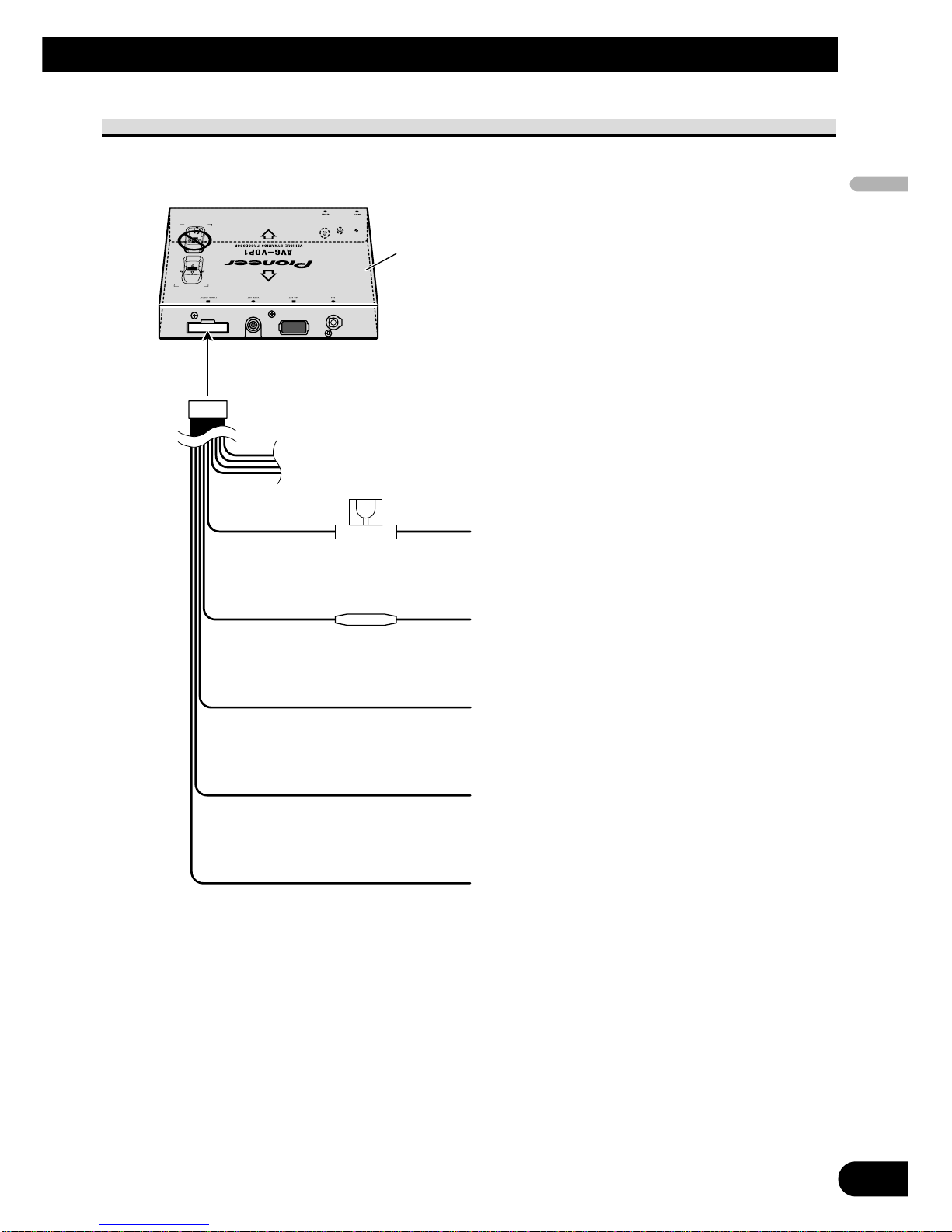
Pioneer AVG-VDP1 User manual

English Español Deutsch Français Italiano Nederlands
AVG-VDP1
This product conforms to new cord colors.
Los colores de los cables de este producto se confor-
man con un nuevo código de colores.
Dieses Produkt entspricht den neuen Kabelfarben.
Le code de couleur des câbles utilisé pour ce produit est
nouveau.
Questo prodotto è conforme ai nuovi codici colori.
De kleuren van de snoeren van dit toestel zijn gewijzigd.
INSTALLATION MANUAL
MANUEL D’INSTALLATION

1
Contents
Connecting the Units ................................ 2
IMPORTANT SAFEGUARDS ........................ 2
Connecting the system ...................................... 5
Connecting the power cord (1) .......................... 6
Connecting the power cord (2) .......................... 7
Installation .................................................. 9
To guard against electromagnetic
interference ................................................ 9
Installing this unit ............................................ 11
Installing the GPS antenna .............................. 12

English Español Deutsch Français Italiano Nederlands
Connecting the Units
2
IMPORTANT SAFEGUARDS
Before using your Vehicle Dynamics
Processor, be sure to read and fully under-
stand the following safety information.
1 Read this manual fully and carefully
before operating your Vehicle
Dynamics Processor.
2 Keep this manual handy as a refer-
ence for future reference.
3 Pay close attention to all warnings
in this manual and follow the
instructions carefully.
4 Do not install the display where it
may (i) obstruct the driver’s vision,
(ii) impair the performance of any
of the vehicle’s operating systems or
safety features, including air bags,
hazard lamp buttons or (iii) impair
the driver’s ability to safely operate
the vehicle.
5 As with any accessory in your vehi-
cle’s interior, the display should not
divert your attention from the safe
operation of your vehicle. If you
experience difficulty in operating
the system or reading the display,
please park safely before making
adjustments.
6 Do not attempt to install or service
your Vehicle Dynamics Processor
by yourself. Installation or servicing
of the Vehicle Dynamics Processor
by persons without training and
experience in electronic equipment
and automotive accessories may be
dangerous and could expose you to
the risk of electric shock or other
hazards and can cause damage to
the system that is not covered by
warranty.
7 Please remember to wear your seat
belt at all times while operating
your vehicle. If you are ever in an
accident, your injuries can be con-
siderably more severe if your seat
belt is not properly buckled.
8 To promote safety, certain functions
are disabled unless the parking
brake is applied.

3
Connecting the Units
WARNING:
• To avoid the risk of accident and the
potential violation of applicable laws,
certain functions of this unit should
never be used while the vehicle is being
driven. Also, rear displays should not be
in a location where it is a visible distrac-
tion to the driver.
• In some countries or states the viewing
of images on a display inside a vehicle
even by persons other than the driver
may be illegal. Where such regulations
apply, they must be obeyed.
CAUTION:
• PIONEER does not recommend that
you install or service your Vehicle
Dynamics Processor yourself. Installing
or servicing the product may expose you
to risk of electric shock or other haz-
ards. Refer all installation and servicing
of your Vehicle Dynamics Processor to
authorized Pioneer service personnel.
• Secure all wiring with cable clamps or
electrical tape. Do not allow any bare
wiring to remain exposed.
• Do not drill a hole into the engine com-
partment to connect the yellow lead of
the unit to the vehicle battery. Engine
vibration may eventually cause the insu-
lation to fail at the point where the wire
passes from the passenger compartment
into the engine compartment. Take
extra care in securing the wire at this
point.
• It is extremely dangerous to allow the
GPS antenna cable to become wound
around the steering column or shift
lever. Be sure to install the unit in such
a way that it will not obstruct driving.
• Make sure that wires will not interfere
with moving parts of the vehicle, such as
the shift lever, parking brake or seat
sliding mechanism.
• Do not shorten any leads. If you do, the
protection circuit may fail to work
properly.

English Español Deutsch Français Italiano Nederlands
4
Note:
• This unit is for vehicles with a 12-volt battery and
negative grounding. Before installing it in a recre-
ational vehicle, truck, or bus, check the battery
voltage.
• To avoid shorts in the electrical system, be sure to
disconnect the ≠battery cable before beginning
installation.
• Refer to the owner’s manual for details on
connecting the power amp and other units, then
make connections correctly.
• Secure the wiring with cable clamps or adhesive
tape. To protect the wiring, wrap adhesive tape
around them where they lie against metal parts.
• Route and secure all wiring so it cannot touch any
moving parts, such as the gear shift, handbrake
and seat rails. Do not route wiring in places that
get hot, such as near the heater outlet. If the insu-
lation of the wiring melts or gets torn, there is a
danger of the wiring short-circuiting to the vehicle
body.
• Don’t pass the yellow lead through a hole into the
engine compartment to connect to the battery.
This will damage the lead insulation and cause a
very dangerous short.
• Do not cut the GPS antenna cable to shorten it or
use an extension to make it longer. Altering the
antenna cable could result in a short circuit or
malfunction.
• Do not shorten any leads. If you do, the protection
circuit may fail to work when it should.
• Never feed power to other equipment by cutting
the insulation of the power supply lead of the unit
and tapping into the lead. The current capacity of
the lead will be exceeded, causing overheating.
• When replacing the fuse, be sure to only use a
fuse of the rating prescribed on the fuse holder.
• If this unit is installed in a vehicle that does not
have an ACC (accessory) position on the ignition
switch, the red lead of the unit should be connect-
ed to a terminal coupled with ignition switch
ON/OFF operations. If this is not done, the vehi-
cle battery may be drained when you are away
from the vehicle for several hours.
No ACC positionACC position
O
N
S
T
A
R
T
O
F
F
A
C
C
O
N
S
T
A
R
T
O
F
F
• Cords for this product and those for other prod-
ucts may be different colors even if they have
the same function. When connecting this product
to another product, refer to the supplied manuals
of both products and connect cords that have the
same function.

5
Connecting the Units
Connecting the system
This unit
Guide speaker
(e.g. CD-TS37GP)
(sold separately)
GPS antenna
Yellow
Black 26 pin cable Display unit
(sold separately)
Video recorder with
RCA input jack
(sold separately)
To video input
RCA cable
(sold separately)
5 m
6 m
This unit’s guide speaker output terminal is used in
the following condition:
When the multi-channel processor and the display
unit that does not have a speaker output terminal is
connected to this unit.
Note:
• In the following cases, images may not be dis-
played properly on the display/VCR:
- When not displaying the V. D. P. image out-
put from this unit on the front display.
- When connecting the display/VCR which
has incompatible video output format with
this unit’s VIDEO OUT.
For more details, refer to the operation manual.

6
English Español Deutsch Français Italiano Nederlands
Connecting the power cord (1)
Fuse (4 A)
This unit
Fuse resistor
Yellow
To terminal always supplied with power
regardless of ignition switch position.
Red
To electric terminal controlled by ignition
switch (12 V DC) ON/OFF.
Black (ground)
To vehicle (metal) body.
White/black
To negative pole of the front left speaker
lead.
Gray/black
To negative pole of the front right speaker
lead.

7
Connecting the Units
Connecting the power cord (2)
Pink
Used to detect the distance the vehicle travels.
Always connect the vehicle’s speed detection cir-
cuit. Failure to make this connection will increase
errors in GPS locator.
WARNING:
IMPROPER CONNECTION MAY RESULT IN
SERIOUS DAMAGE OR INJURY INCLUDING
ELECTRICAL SHOCK, AND INTERFERENCE
WITH THE OPERATION OF THE VEHICLE’S
ANTILOCK BRAKING SYSTEM, AUTOMATIC
TRANSMISSION AND SPEEDOMETER INDICA-
TION.
Note:
• The position of the speed detection circuit
depends on the vehicle model. For details, con-
sult your authorized Pioneer dealer or an instal-
lation professional.
Pink/black
Not used.

English Español Deutsch Français Italiano Nederlands
8
This unit
Violet/white
Of the two lead wires connected to the back lamp,
connect the one in which the voltage changes when
the gear shift is in REVERSE (R) position. If not
connected, this unit does not work properly.
Fuse resistor
Connection method
1. Clamp the lead. 2. Clamp firmly with
needle-nosed pliers.
Light green
Used to detect the ON/OFF status of the parking brake.
This lead must be connected to the power supply side of
the parking brake switch.
Parking brake
switch
Power supply side
Ground side
Note:
• The position of the parking
brake switch depends on the
vehicle model. For details,
consult the vehicle owner’s
manual or dealer.
WARNING:
LIGHT GREEN LEAD AT POWER CONNECTOR IS
DESIGNED TO DETECT PARKED STATUS AND
MUST BE CONNECTED TO THE POWER SUPPLY
SIDE OF THE PARKING BRAKE SWITCH.
IMPROPER CONNECTION OR USE OF THIS LEAD
MAY VIOLATE APPLICABLE LAW AND MAY
RESULT IN SERIOUS INJURY OR DAMAGE.

9
Installation
Note:
• Before making a final installation of the unit,
temporarily connect the wiring to confirm that the
connections are correct and the system works
properly.
• Use only the parts included with the unit to
ensure proper installation. The use of unautho-
rized parts can cause malfunctions.
• Consult with your nearest dealer if installation
requires the drilling of holes or other modifica-
tions of the vehicle.
• Install the unit where it does not get in the dri-
ver’s way and cannot injure the passenger if there
is a sudden stop, like an emergency stop.
• When mounting this unit, make sure none of the
leads are trapped between this unit and the sur-
rounding metalwork or fittings.
• Do not mount this unit near the heater outlet,
where it would be affected by heat, or near the
doors, where rainwater might splash onto it.
• Before drilling any mounting holes always check
behind where you want to drill the holes. Do not
drill into the gas line, brake line, electrical wiring
or other important parts.
• If this unit is installed in the passenger compart-
ment, anchor it securely so it does not break free
while the car is moving, and cause injury or an
accident.
• If this unit is installed under a front seat, make
sure it does not obstruct seat movement. Route all
leads and cords carefully around the sliding
mechanism so they do not get caught or pinched
in the mechanism and cause a short circuit.
• Do not install this unit on the board covering the
spare tire or other places which are subject to
vibration.
• When installing this unit, choose a position that
ensures there will be no contact with luggage.
The impact of a heavy weight or sudden shock on
this unit will adversely affect the accurate display
of the current location of the vehicle.
• Avoid installing this unit in places where it will
interfere with loading and unloading of the spare
tire, jack, tools, etc.
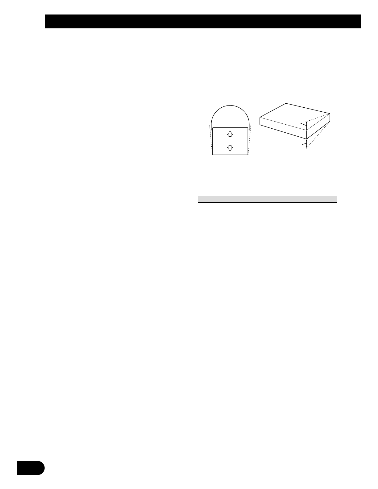
• Install this unit horizontally on a surface within
+30º to –30º tolerance (within 5º to the left or
right of your vehicle’s direction of travel). Mis-
installing the unit with the surface tilted more
than these tolerances would increase the potential
for errors in the location display, and might other-
wise cause reduced display performance.
To guard against electromagnetic
interference
In order to prevent interference, set the
following items as far as possible from
this unit, other cables or leads:
- TV antenna and its lead
- Radio antenna and its lead
- GPS antenna and its lead
In addition you should lay or route each
antenna lead as far as possible from other
antenna leads.
Do not bind them together, lay or route
them together, or cross them.
Such electromagnetic noise will increase
the potential for errors in the location dis-
play.
30°
30°
5°

English Español Deutsch Français Italiano Nederlands
10
CAUTION:
• Install with the left and right sides of this unit perpendicular or parallel to
your vehicle’s direction of travel. Do not install diagonally to your vehicle’s
direction of travel or the current location will be displayed incorrectly.
• Be sure to install this unit on the floor with the silk printing side is facing up.
This unit will operate properly only in this position.
Forward/backward
direction of vehicle

11
Installation
Installing this unit
1. Attach the side brackets to this unit.
When this unit is installed on the floor or
the installation board under the passenger
seat, etc., the side brackets should be
attached to the unit.
Use the following holes in the side
brackets.
If the positions of the side plates
are shifted in parallel you can also
use other holes that match up with
the holes in this unit.
When this unit is installed under the pas-
senger seat, etc., use the installation board.
2. Decide on the installation position,
and drill the holes.
3. Secure it firmly using the self-tap-
ping screws.
Drill holes of between
4 and 4.5 mm in
diameter.
Installation board Mark up the positions for
drilling the holes.
Self-tapping screw
(6 × 16 mm)
This unit
Washer faced
screw (4 × 8 mm)
Side bracket

12
English Español Deutsch Français Italiano Nederlands
Installing the GPS antenna
CAUTION:
• Do not cut the GPS antenna lead
to shorten it or use an extension
to make it longer. Altering the
antenna cable could result in a
short circuit or malfunction and
permanent damage to the prod-
uct.
Installation notes
•The antenna should be installed on a level
surface where radio waves will be blocked
as little as possible. Radio waves cannot be
received by the antenna if reception from
the satellite is blocked.
Installation on the vehicle roof or trunk lid is
recommended to optimise reception.
•When installing the GPS antenna inside the
vehicle, be sure to use the metal sheet
provided with your system. If this is not
used, the reception sensitivity will be poor.
•Do not cut the accessory metal sheet. This
would reduce the sensitivity of the GPS
antenna.
•Take care not to pull the antenna lead when
removing the GPS antenna. The magnet
attached to the antenna is very powerful, and
the lead may become detached.
•The GPS antenna is installed with a magnet.
When installing the GPS antenna, be careful
not to scratch the vehicle body.
•When installing the GPS antenna on the out-
side of the vehicle, always put it in the vehi-
cle when going through an automatic vehi-
cle wash. If it is left on the outside it may be
knocked off and scratch the vehicle body.
•Do not paint the GPS antenna, as this may
affect its performance.
Trunk lid
Roof Rear shelf

13
Installation
When installing the antenna inside the vehicle (on the rear shelf)
Affix the metal sheet on as level a surface as possible where the GPS antenna faces the
window. Place the GPS antenna on the metal sheet. (The GPS antenna is fastened with its
magnet.)
Note:
•When attaching the metal sheet, do not cut it into small pieces.
•Some models use window glass that does not allow signals from GPS satellites to pass through. On
such models, install the GPS antenna on the outside of the vehicle.
GPS antenna Metal sheet
Peel off the protective sheet.
Make sure the surface is free of
moisture, dust, grime, oil, etc.,
before affixing the metal sheet.
Note:
•The metal sheet contains a
strong adhesive which may
leave a mark on the surface
if it is removed.
Clamps
Use clamps to secure the
lead where necessary inside
the vehicle.

14
English Español Deutsch Français Italiano Nederlands
When installing the antenna outside the vehicle (on the body)
Put the GPS antenna in a position as level as possible, such as on the roof or trunk lid. (The
GPS antenna is fastened with a magnet.)
GPS antenna
When routing the lead in from the top of the
door
Clamps
Use clamps to secure
the lead where nec-
essary inside the
vehicle.
Make a U-shaped loop in the lead
on the outside to prevent rainwater
from flowing along the lead into
the interior of the vehicle.
When routing the lead in from inside the trunk
Clamps
Use clamps to secure the
lead where necessary
inside the vehicle.
Make a U-shaped loop in the
lead outside the rubber pack-
ing to prevent rainwater from
flowing along the lead into
the interior of the vehicle.
Waterproof pad
Make sure the waterproof
pad contacts the top of the
rubber packing.
Rubber packing

1
Contenido
Conexión de las unidades ........................ 2
INSTRUCCIONES DE SEGURIDAD
IMPORTANTES ........................................ 2
Conexión del sistema ........................................ 5
Conexión de cable de alimentación (1) ............ 6
Conexión de cable de alimentación (2) ............ 7
Instalación .................................................. 9
Protección contra la interferencia
electromagnética ........................................ 9
Instalación de esta unidad .............................. 11
Instalación de la antena GPS .......................... 12

English Español Deutsch Français Italiano Nederlands
Conexión de las unidades
2
INSTRUCCIONES DE SEGURIDAD
IMPORTANTES
Antes de utilizar su Procesador de
Dinámica de Vehículo, asegúrese de leer y
de entender completamente la siguiente
información de seguridad.
1 Lea este manual atentamente antes
de operar su Procesador de
Dinámica de Vehículo.
2 Guarde este manual a mano como
una referencia para futuras
consultas.
3 Tenga especial atención a todas las
advertencias en este manual y siga
las instrucciones cuidadosamente.
4 No instale la pantalla donde pueda
(i) obstruir la visión del conductor,
(ii) perjudicar el rendimiento de
cualquier sistema de operación o
funciones de seguridad del vehículo,
incluyendo los air bags, botón de la
luz de peligro, o (iii) perjudicar la
habilidad del conductor para operar
el vehículo con seguridad.
5 Como con cualquier accesorio en el
interior de su vehículo, la pantalla
no debe distraer su atención de la
operación segura del vehículo.
Cuando encuentre dificultad en
operar al operar el sistema o leer la
pantalla, estacione el vehículo con
seguridad antes de hacer ajustes.
6 No intente instalar o reparar su
Procesador de Dinámica de
Vehículo usted mismo. La
instalación o servicio del Procesador
de Dinámica de Vehículo por
personas sin entrenamiento y
experiencia en equipos electrónicos
y accesorios de automóvil puede ser
peligroso y puede exponerle al
riesgo de descarga eléctrica u otros
peligros, y también puede causar
daños al sistema que no están
cubiertos por la garantía.
7 Acuérdese de utilizar siempre el
cinturón de seguridad mientras
conduce el vehículo. En el caso de
un accidente, sus lesiones pueden
ser considerablemente más graves si
su cinturón de seguridad no está
abrochado adecuadamente.
8 Para aumentar la seguridad, ciertas
funciones se desactivan a menos que
se aplique el freno de
estacionamiento.

3
Conexión de las unidades
ADVERTENCIA:
• Para evitar el riesgo de accidente y
violación potencial de las leyes
aplicables, no se deben utilizar nunca
ciertas funciones de esta unidad
mientras se conduce el vehículo.
Igualmente, las pantallas traseras no
deben ubicarse donde presenten una
distracción visible al conductor.
• En algunos países o estados, puede que
sea ilegal la visualización de las
imágenes en una pantalla dentro de un
vehículo, aún por los pasajeros. Donde
haya tales regulaciones, se debe
obedecerlas.
PRECAUCIÓN:
• PIONEER no recomienda que usted
mismo instale o intente reparar su
Procesador de Dinámica de Vehículo.
La instalación o servicio del producto
puede exponerle al riesgo de descarga
eléctrica u otros peligros. Solicite toda la
instalación y servicio de su Procesador
de Dinámica de Vehículo al personal de
servicio autorizado de Pioneer.
• Fije todo el cableado con abrazaderas
de cable o con cinta eléctrica. No permi-
ta que cualquier hilo desnudo per-
manezca expuesto.
• No taladre un agujero en el compar-
timiento del motor para conectar el
cable amarillo de la unidad a la batería
del vehículo. La vibración del motor
puede eventualmente causar el deterioro
del aislamiento en el punto donde el hilo
pasa del compartimiento de pasajeros al
compartimiento del motor. Tenga espe-
cial cuidado al fijar el hilo en este punto.
• Es extremamente peligroso permitir que
el cable de la antena GPS se enrolle
alrededor de la columna de la dirección
o palanca de cambio. Asegúrese de
instalar la unidad de manera que no
obstruya la conducción del vehículo.
• Asegúrese de que los hilos no interfieran
con las piezas móviles del vehículo,
como la palanca de cambio, freno de
estacionamiento o mecanismo de
deslizamiento de los asientos.
• No acorte ningún hilo. De lo contrario,
el circuito de protección podría dejar de
funcionar adecuadamente.

English Español Deutsch Français Italiano Nederlands
4
Nota:
• Esta unidad es para vehículos con una batería de
12 voltios y conexión a tierra negativa. Antes de
instalarla en un vehículo recreativo, camioneta o
autobús, verifique el voltaje de la batería.
• Para evitar cortocircuitos en el sistema eléctrico,
asegúrese de desconectar el cable ≠de la batería
antes de iniciar la instalación.
• Consulte el manual del propietario para los
detalles acerca de la conexión del amplificador de
potencia y de otras unidades y, a continuación,
haga las conexiones correctamente.
• Fije el cableado con abrazaderas de cable o con
cinta adhesiva. Para proteger el cableado,
envuélvalo con cinta adhesiva donde el cableado
se apoya sobre piezas metálicas.
• Encamine y fije el cableado de manera que no
toque las piezas móviles como el cambio de
marchas, freno de mano y rieles de los asientos.
No encamine el cableado en lugares que se
quedan calientes, como cerca de la salida del
calentador. El derretimiento o daño de los hilos
crea el peligro de cortocircuitos a través de la
carrocería del vehículo.
• No pase el cable amarillo a través de un agujero
en el compartimiento del motor para conectar la
batería. Esto dañará el aislamiento del cable y
causará un cortocircuito muy peligroso.
• No corte el cable de la antena GPS para acortarlo
ni utilice una extensión para alargarlo. Modificar
el cable de la antena podría causar un corto-
circuito o fallo de funcionamiento.
• No acorte ningún hilo. De lo contrario, el circuito
de protección podría dejar de funcionar cuando
debería.
• No suministre nunca energía a otros equipos
cortando el aislamiento del cable de alimentación
de la unidad y haciendo una derivación con otro
hilo. La capacidad de corriente del hilo se
excederá, causando un sobrecalentamiento.
• Cuando reemplace el fusible, asegúrese de utilizar
solamente un fusible del régimen indicado en el
portafusible.
• Si se instala esta unidad en un vehículo que no
tiene una posición ACC (accesorio) en el
interruptor de encendido, se debe conectar el
cable rojo de la unidad al terminal acoplado con
las operaciones de encendido/apagado del
interruptor de encendido. Si no se hace esto, la
batería del vehículo puede descargarse cuando
esté fuera del vehículo por varias horas.
Sin posición ACCPosición ACC
O
N
S
T
A
R
T
O
F
F
A
C
C
O
N
S
T
A
R
T
O
F
F
• Los cables para este producto y los cables para
otros productos pueden tener colores diferentes
aunque tengan la misma función. Cuando
conecte este producto a otro producto, consulte
los manuales suministrados de ambos los
productos y conecte los cables que tienen la
misma función.

5
Conexión de las unidades
Conexión del sistema
Esta unidad
Altavoz de guía
(por ejemplo, CD-TS37GP)
(vendido separadamente)
Antena GPS
Amarillo
Negro Cable de 26 clavijas Pantalla
(vendida separadamente)
Videograbadora con toma
de entrada RCA
(vendida separadamente)
A la entrada de vídeo
Cable RCA
(vendido separadamente)
5 m
6 m
El terminal de salida del altavoz de guía de esta
unidad se utiliza en la siguiente condición:
Cuando se conecta a esta unidad un procesador de
canales múltiples y una pantalla que no tienen un
terminal de salida de altavoz.
Nota:
• En los siguientes casos, puede que las imá-
genes no se visualicen apropiadamente en el
monitor/videograbadora:
- Cuando no se esté visualizando la imagen
V.D.P. emitida por esta unidad en el monitor
frontal.
- Cuando se conecta un
monitor/videograbadora que tenga un forma-
to de salida de vídeo incompatible con el ter-
minal VIDEO OUT de esta unidad.
Para los detalles, consulte el manual de
operación.
Other manuals for AVG-VDP1
5
Table of contents
Languages:
Other Pioneer Automobile Electronic manuals
Popular Automobile Electronic manuals by other brands

Pyle
Pyle Bluetooth Dialing Car Kit PBT78XP user manual

Bojo
Bojo VTC433H instruction manual

Conrad
Conrad 85 69 98 operating instructions

Dakota Digital
Dakota Digital LED Tail Lights LAT-NR350 installation instructions

KAP
KAP KPLAY2 instruction manual

VDO
VDO PITOT-TUBE SPEEDOMETER SET installation instructions

Sony
Sony PEGA-CC5 operating instructions

Renault
Renault PARK MASTER user manual

Mitsubishi MOTORS
Mitsubishi MOTORS MZ380456EX installation manual

Rear view safety
Rear view safety RVS-155W instruction manual

Continental Refrigerator
Continental Refrigerator ARS3-B instruction manual

Polaroid
Polaroid C207 user guide