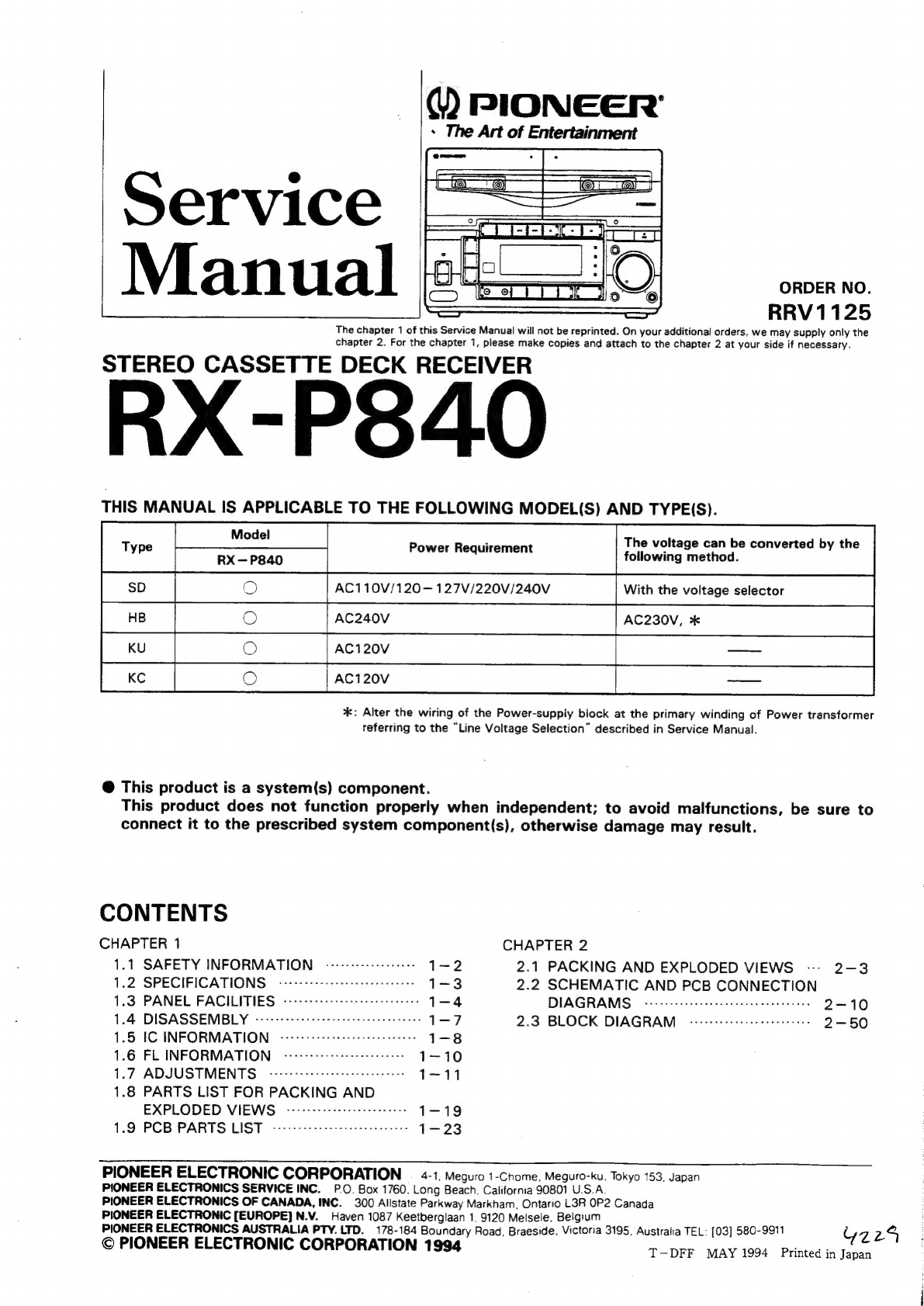
Pioneer RX-P840 User manual

®
PIONEER’
s
The
Art
of
Entertainment
aE
_
OA
i
a
OFM
Ol
Stee
Service
a
$F
TPL
|
6
Manual
0)
on
RRV1125
The
chapter
1
of
this
Service
Manual
will
not
be
reprinted.
On
your
additional
orders,
we
may
supply
only
the
chapter
2.
For
the
chapter
1,
please
make
copies
and
attach
to
the
chapter
2
at
your
side
if
necessary.
STEREO
CASSETTE
DECK
RECEIVER
RX-P840
THIS
MANUAL
IS
APPLICABLE
TO
THE
FOLLOWING
MODEL(S)
AND
TYPE(S).
5
The
voltage
can
be
converted
by
the
Tape
RX
—P840
Power
Roauseinent
following
method.
AC110V/120—127V/220V/240V
With
the
voltage
selector
VU
HB
@
AC240V
AC230V,
*
KU
oO
AC120V
_—
Ke
3
AGI20V
Sa
%*:
Alter
the
wiring
of
the
Power-supply
block
at
the
primary
winding
of
Power
transformer
referring
to
the
“Line
Voltage
Selection”
described
in
Service
Manual.
@
This
product
is
a
system(s)
component.
This
product
does
not
function
properly
when
independent;
to
avoid
malfunctions,
be
sure
to
connect
it
to
the
prescribed
system
component(s),
otherwise
damage
may
result.
CONTENTS
CHAPTER
1
CHAPTER
2
1.1
SAFETY
INFORMATION
--------2
1-2
2.1
PACKING
AND
EXPLODED
VIEWS
--
2-3
1.2
SPECIFICATIONS
v-11eeeeeeee
1-3
2.2
SCHEMATIC
AND
PCB
CONNECTION
1.3
PANEL
FACILITIES
nee
eee
taste
mane
ceeeneceoer
1
—-4
DIAGRAMS
OSES
eee
ee
cee
sence
cece
beeen
eease
2-10
1.4
DISASSEMBLY
wee
eww
ea
anes
neta
reece
ceseces
1
-7
2.3
BLOCK
DIAGRAM
eee
eee
nen
ee
meme
ne
eaee
2-50
1.5
IC
INFORMATION
biota
stelle
love
Sua
itiai
ayers
shanate
sian
1-8
1.6
FL
INFORMATION
Beas
e
ede
sea
veet
cenaeeues
1
—_
10
1.7
ADJUSTMENTS
Wale
Gistiie
Sind
gelgike
die
vata
5.0
/5%G,
alate"
1-11
1.8
PARTS
LIST
FOR
PACKING
AND
EXPLODED
VIEWS
a
Ssh
8
Sale
eae
korean
ole
aca
evele
1
—
1
9
1.9
PCB
PARTS
LIST
piled
iia
Byala.
ea
fave
olarlese
java
ted
oA
ene;
des
1
-—23
PIONEER
ELECTRONIC
CORPORATION
=
4-1,
Meguro
1-Chome,
Meguro-ku.
Tokyo
153,
Japan
PIONEER
ELECTRONICS
SERVICE
INC.
P.O.
Box
1760.
Long
Beach.
California
90801
U.S.A.
PIONEER
ELECTRONICS
OF
CANADA,
INC.
300
Allstate
Parkway
Markham,
Ontario
L3R
OP2
Canada
PIONEER
ELECTRONIC
[EUROPE]
N.V.
Haven
1087
Keetberglaan
1,
9120
Melsele,
Belgium
PIONEER
ELECTRONICS
AUSTRALIA
PTY.
LTD.
178-184
Boundary
Road,
Braeside,
Victoria
3195,
Australia
TEL:
[03]
580-9911
YZ
24
©
PIONEER
ELECTRONIC
CORPORATION
1994
T—DFF
MAY
1994.
Printed
in
Japan

RX-P840
CHAPTER
1
1.1
SAFETY
INFORMATION
This
service
manual
is
intended
for
qualified
service
technicians;
it
is
not
meant
for
the
casual
do-it-yourselfer.
Qualified
technicians
have
the
necessary
test
equipment
and
tools,
and
have
been
trained
to
properly
and
safely
repair
complex
products
such
as
those
covered
by
this
manual.
Improperly
performed
repairs
can
adversely
affect
the
safety
and
reliability
of
the
product
and
may
void
the
warranty.
If
you
are
not
qualified
to
perform
the
repair
of
this
product
properly
and
safely,
you
should
not
risk
trying
to
do
so
and
refer
the
repair
to
a
qualified
service
technician.
WARNING
Lead
in
solder
used
in
this
product
is
listed
by
the
California
Health
and
Welfare
agency
as
a
known
reproductive
toxicant
which
may
cause
birth
defects
or
other
reproductive
harm
(California
Health
&
Safety
Code,
Section
25249.5).
When
servicing
or
handling
circuit
boards
and
other
components
which
contain
lead
in
solder,
avoid
unprotected
skin
contact
with
the
solder.
Also,
when
soldering
do
not
inhale
any
smoke
or
fumes
produced.
NOTICE
(FOR
CANADIAN
MODEL
ONLY)
Fuse
symbols
-f&—4
(fast
operating
fuse)
and/or
~-§&—
(slow
operating
fuse)
on
PCB
indicate
that
replacement
parts
must
be
of
identical
designation.
REMARQUE
(POUR
MODELE
CANADIEN
SEULEMENT)
Les
symboles
de
fusible
-§——1
(fusible
de
type
rapide)
et/ou
-§—#
(fusible
de
type
lent)
sur
CCi
indiquent
que
les
piéces
de
remplacement
doivent
avoir
la
méme
désignation.
(FOR
USA
MODEL
ONLY)
1.SAFETY
PRECAUTIONS
The
following
check
should
be
performed
for
the
continued
protection
of
the
customer
and
service
technician.
LEAKAGE
CURRENT
CHECK
Measure
leakage
current
to
a
known
earth
ground
(water
pipe,
conduit,
etc.)
by
connecting
a
leakage
current
tester
such
as
Simpson
Model
229-2
or
metal
parts
of
the
appliance
(input/output
terminals,
screwheads,
metal
overlays,
control
shaft,
etc.).
Plug
the
AC
line
cord
of
the
appliance
directly
into
a
120V
AC
60Hz
outlet
and
turn
the
AC
power
switch
on.
Any
current
measured
must
not
exceed
0.5mA.
Reading
should
Leakage
|
20t
be
above
current
|
0.5mMA
tester
°
Test
ail
exposed
metal
surfaces
Also
test
with
plug
reversed
(Using
AC
adapter
plug
as
required)
Earth
ground
AC
Leakage.
Test
equivalent
between
the
earth
ground
and
ail
exposed
|
ANY
MEASUREMENTS
NOT
WITHIN
THE
LIMITS
OUTLINED
ABOVE
ARE
INDICATIVE
OF
A
PO-
TENTIAL
SHOCK
HAZARD
AND
MUST
BE
COR-
RECTED
BEFORE
RETURNING
THE
APPLIANCE
TO
THE
CUSTOMER.
2.PRODUCT
SAFETY
NOTICE
Many
electrical
and
mechanical
parts
in
the
appli-
ance
have
special
safety
related
characteristics.
These
are
often
not
evident
from
visual
inspection
nor
the
protection
afforded
by
them
necessarily
can
be
ob-
tained
by
using
replacement
components
rated
for
vol-
tage,
wattage,
etc.
Replacement
parts
which
have
these
special
safety
characteristics
are
identified
in
this
Service
Manual.
Electrical
components
having
such
features
are
identified
by
marking
with
a
A
on
the
schematics
and
on
the
parts
list
in
this
Service
Manual.
The
use
of
a
substitute
replacement
component
which
dose
not
have
the
same
safety
characteristics
as
the
PIONEER
recommended
replacement
one,
shown
in
the
parts
list
in
this
Service
Manual,
may
create
shock,
fire,
or
other
hazards.
Product
Safety
is
continuously
under
review
and
new
instructions
are
issued
from
time
to
time.
For
the
latest
information,
always
consult
the
current
PIONEER
Service
Manual.
A
subscription
to,
or
éd-
ditional
copies
of,
PIONEER
Service
Manual
may
be
obtained
at
a
nominal
charge
from
PIONEER.

1.2
SPECIFICATIONS
@
STEREO
CASSETTE
DECK
RECEIVER:
RX-P840
Amplifier
Section
<U.S.
model>
Continuous
Average
Power
Output
is
70
Watts*
per
channel,
min.,
at
8
ohms
from
40
Hz
to
20,000
Hz
with
no
more
than
0.9
%**
total
harmonic
distortion.
Continuous
power
output
(RMS)
Sacto
leita
osetia
100
W+100
W
(1
kHz,
T.H.D.
10%,
8
Q)
Continuous
power
output
(DIN)
Sisusd
Wesstbecdshecsesutescccets
75
W+75
W
(1
kHz,
T.H.D.
1%,
8
Q)
Music
power
(DIN).........ccceesccscesetscseeeeeees
324
W
(Total)
Peak
music
power
output
(Muiti-voitage
model
only)...........ceeeseeeeeees
730
W/8
Q
FM
Tuner
Section
Reception
frequencies...
ee
eeeeeeeeeeeee
87.5
—
108
MHz
AM
Tuner
Section
Reception
frequencies
...............
531
kHz
—
1602
kHz
(9k)
530
kHz
-
1700
kHz
(10k)
ANTENNA
ou.
.cecesssscececesneeccecereecens
Loop
antenna
(included)
Double
Cassette
Deck
Section
SYSTEM
tyPe
ou...
eeccseceesseereee
4-track,
2-channe!
stereo
Heads
2rcc2
oi
idedenedciecnee.
Recording/playback
head
x
1
Playback
head
x
1
Erasing
head
x
1
MOTOR
i
ssehscenccsht
stvnctesenuceseianstasesetnccnsed
DC
servo
motor
x
1
Type
Il
(High/CrO:2)
tape
sig
abivecn
dest
us
dtevbantdarvsieuseudcaetccees
*35
Hz
-
15,000
Hz
+6dB
(recorded
at
-20
dB)
Type
|
(Normal)
tape.............
*35
Hz
-
14,000
Hz
+6dB8
(recorded
at
-20
dB)
Frequency
response
SNiratiocisiesceesisedpucseeeds
dies
aecsateeaienttes
*56
dB
(peak
recording
level,
audible
compensation)
Dolby
B
type
NR
on
....10
dB
compensation
at
5
kHz
Dolby
C
type
NR
on
....19
dB
compensation
at
5
kHz
*Values
measured
in
accordance
with
EIAJ
standards.
RX-P840
m@
ELECTRICAL
REQUIREMENTS,
ETC.
Power
requirements
U:S.
Modelisic.elasa
i
eliescnnks
AC
120
V,
60 Hz
U.K.
model...
ceeeesseseseeeeee
AC
240
Volts~,
50/60
Hz
Muiti-voltage
model
Stereo
deck
receiver
section........
AC
110/120
—
127/
220/240
V
(Switchable),
50/60
Hz
Power
consumption
Stereo
deck
receiver
section
US
HMOd!
ieoioccscucesites
ach
custis
classes
cuaesiecacscideowe
170
W
U.K.
and
Multi-voitage
models..............:ceee
390
W
AC
OUTLET
......
eee
UNSWITCHED
100
W
MAX
x
1
External
dimensions
Stereo
deck
receiver
section
shots
ssdusastdscudacccansssectece
260
(W)
x
185
(H)
x
365
(D)
mm
10-1/4
(W)
x
7-5/16
(H)
x
14-3/8
(D)
in.
Weight
Stereo
deck
receiver
section...........7.3
kg
(16
Ib
3
02)

RX-P840
1.3
PANEL
FACILITIES
The
illustration
shows
Multi-voltage
model.
®
@
POWER
STANDBY/ON
switch/STANDBY
indicator
This
is
the
switch
for
electric
power.
ON:
When
set
to
the
ON
position,
power
is
supplied
and
the
unit
becomes
oper-
ational.
STANDBY:
When
set
to
the
STANDBY
position,
the
main
power
flow
is
cut
and
the
unit
is
no
longer
fully
operational.
A
minute
flow
of
power
feeds
the
unit
to
main-
tain
operation
readiness.
@
Remote
control
sensor
(REMOTE
SENSOR)
@®
TAPE1/2
select
button
@
DOLBY*
NR
select
button
(B/C/OFF)
*
*
Dolby
noise
reduction
manufactured
under
license
from
Dolby
Laboratories
Licensing
Corporation.
°
“DOLBY”
and
the
double-D
symbol
OO
are
trademarks
of
Dolby
Laboratories
Licensing
Corporation.
©
TAPE
|
EJECT
port
(4)
©
Display
@
TAPE
Il
EJECT
port
(4)
TAPE
1/2
operating
buttons
(<<,
>>,
&,
<4,
>)
@®
Function
select
indicator
(TUNER,
TAPE,
CD,
MD/AUX)
@
Sound
Field
Control
(SFC
MODE)button
@
ASES/COPY
button
@
Record/pause
button
(etl)
@
Microphone
jack
(MIC)
and
microphone
level
control
(MIC
LEVEL)
(Multi-voltage
model
only)
Clock
adjust
button
(CLOCK-ADJ)
@®
WAKE-UP
button
@
Timer
recording
button
(TIMER
REC)
@
TUNING
(+,
-)
button
8
BAND
button
@
MEMORY
button
@
AUTO
TUNING
button
@
Frequency/station
button
(FREQ./STATION)
@
FUNCTION
select
button
(DEMO
button)
Each
time
this
button
is
pressed,
the
function
changes
in
the
following
sequence:
ia
TUNER
——®
TAPE
—*
CD
MD/AUX
ao
@
P.BASS
button
@
VOLUME
control
@
Headphone
jack
(PHONES)

REMOTE
CONTROL
UNIT
RX-P840
@
For
U.K.
mode!
(5B,
5C)
Press
and
slide
the
upper
lid
surface
to
open
the
remote
control
unit
case.
Controls
shown
here
without
special
instructions
indi-
cate
functions
which
are
the
same
as
those
found
on
the
main
deck-receiver
unit.
@
Display
window
Displays
the
current
operation.
@
System
function
buttons
POWER
seisee
Power
switch
(ON/STANDBY)
Scdtisteteuveee
Function
select
button
ue
shades
Main
volume
seeseteabevets
Sound
field
selector
selescevatace'ed
Stereo
wide
pattern
selector
button
dadscsucsoots
Bass
boost
mode
button
@)
TUNER
operation
buttons
TUNER
STATION
agaseae
Use
for
calling
radio
stations
stored
in
the
station
memory.
Broadcast
stations
must
be
stored
in
the
station
memory
before
operating.
ANA
bascdtisdseins
FM/AM
selector
eistbesaisaeg,
FM
stereo/mono
selector
(operates
ok
vied
only
during
FM
stereo
reception)
Cc)
-
...Station
memory
call
buttons
@
TAPE
|,
TAPE
Il
operation
buttons
Tape
Sesdhais
Use
to
select
Tape
!
or
Tape
Il
a)...
Fast
forward,
rewind
button
C)
ee
Stop
button
G)
©
Sona
Play
buttons
PRUE
ee
eeeceeeeeneee
TAPE
!!
record/pause
button:
This
button
does
not
operate
when
TAPE
|
is
light-
ed
in
the
remote
control
unit's
display.
Switch
first
to
TAPE
Il.
©
CD
operation
buttons
(5A)
Buttons
for
ordinary
operations
Track
search
button
Stop
button
Pause
button
Play
button
Disc
select
button
..Send
button
(transmits
the
play
signal
for
selected
disc
title
to
the
main
unit)
sisiestd
Disc
title
button
{use
to
select
disc
title)
(5B)
Buttons
for
selecting
and
searching
for
disc
titles
*Gee)
.2G)
_.Character
buttons
iugssessadsaue
Input
button
ra
RD
hadnt
Cursor
control
buttons
ci
TOM
<5
seaddlescuccasd
Custom
button
osc
reediacedeniass
Disc
button
netuon
cS
ddedeeadessiies
Return
button
duspebusuataes
Search
button
{5C)
Buttons
for
other
convenient
functions
iy
fora
CC
~
C2
__Dise
and
track
number
setting
(digit)
er
buttons
(Ce
ee
ene
Functions
as
“clear”
button
to
cancel
CD
program
steps.
Also
used
to
erase
al!
discs
select-
ed
with
the
custom
mode.
reack
dei
dcbigeieads
Track
set
button
S)
cudainteds
Disc
set
button
fete
Program
set
button
érSSieeee
cies
Random
play
button
aD
earnenee
Repeat
play
button
seusseseeesee-CD
play
mode
button
Sizcdeieaveas
Time
button

RX-P840
©
TIMER
operation
buttons
WAKE
UP
PE
NF
eeceeee
Use
to
select
wake-up
1
or
wake-up
suser
2
timer
functions.
Lbgosseabcatoees
Sieep
timer
snooze
Cc)
Saesestecosvoye
5-minute
snooze
timer
(restarts
unit
5
minutes
after
wake-up
timer
oper-
ates;
does
not
function
during
nor-
mal
play).
@
RESET
button
This
is
the
remote
control
unit's
system
reset
button.
If
the
remote
control
unit's
display
appears
abnormal
during
use
or
when
exchanging
batteries,
and
the
main
unit
no
longer
responds
to
commands,
press
this
button
to
reset
the
remote
control
unit.
Disc
titles
stored
in
the
memory
are
preserved
even
when
the
RESET
button
is
pressed.
@
For
U.S.
and
Multi-voltage
models
The
illustration
shows
Multi-voitage
model.
@
System
function
buttons
POWER
SS
iiw...........
Power
switch
(ON/STANDBY)
FUNC
died
Function
select
button
vooe
dansiaeetaets
Sound
field
selector
P.B4Ss
shdeaseesdwalss
Bass
boost
mode
button
sr
wide
VOLUME
=a
pebivesuenwie
Main
volume
KARA
KE
d
cgedeeciacede
Stereo
wide
pattern
selector
button
satuesenees
One-touch
karaoke
button
(Multi-volttage
mode!
only)
@
TUNER
operation
buttons
s
gouabeteuiue
FM/AM
selector
re
FM
stereo/mono
selector
(operates
113
s2ea
only
during
FM
stereo
reception)
Cc)
=
...
Station
memory
call
buttons
@
TAPE
I,
TAPE
ll
operation
buttons
(=)
seodiscoisosts
Stop
button
Gs)
ee)
tous
Fast
forward,
rewind
button
TAPE
Il
setae
Play
buttons
Exbe%
sabusédanscent
To
operate
TAPE
|,
press
the
desired
deck
operation
button
while
press-
ing
this
button.
(Except
for
the
Record/pause
(@#1)
button)
ex)
sidece
Record/pause
button
@
CD
operation
buttons
Buttons
for
ordinary
operations
COE)
saete
Disc
select
button
i)
ee)
wise
Track
search
button
oH)
uodanberbeuste
Pause
button
co
@)
bata
Stop
button
te)
Cul
saaieens
Play
button
Buttons
for
other
convenient
functions
143
1022
~
Co)
...Disc
and
track
number
setting
(digit)
1123
buttons
Jeeicacrediee
Functions
as
“clear”
button
to
cancel
CD
program
steps.
Also
used
to
erase
all
discs
selected
with
the
custom
ors
mode.
way
saevancees
Disc
set
button
sseisiesaoce
Track
set
button
eedaastoscae
CD
play
mode
button
ésieieseteiece
Random
play
button
aabathesnaese
Repeat
play
button
ex)
saeeesteecl!
Program
set
button
teed
eee
ccrtidsetetian
Time
button
©
TIMER
operation
buttons
waxe-uP
Mise
detiesess
Use
to
select
wake-up
1
or
wake-up
stcer
2
timer
functions.
sevteecieeass
Sleep
timer
SNOOZE
eri
saates
5-minute
snooze
timer
(restarts
unit
5
minutes
after
wake-up
timer
oper-
ates;
does
not
function
during
nor-
mal
play).

|
RX-P840
1.4
DISASSEMBLY
i
MAIN
ASSY
1.
Remove
the
bonnet
case.
2.
Remove
the
Rear
Panel
Section
@
Remove
the
screw
@
(2
screws)
of
the
antenna
terminal.
@
Remove
the
screw
@
(1
screw)
of
the
pin
jack
(MD/AUX).
@®
Remove
the
screw
@)
(1
screw)
of
the
connector
for
CD.
@
Remove
the
screw
@
(2
screws)
of
the
front
speaker
terminal.
©
Remove
the
screw
©
(1
screw)
of
the
pin
jack
for
surround
speaker.
(SD
and
HB
types
only)
©
Remove
the
screw
©
(1
screw)
between
the
chassis
and
rear
panel.
3.
Remove
the
Front
Panel
Section
@
Remove
the
screw
@
(1
screw)
holding
the
lead
wire
from
the
cassette
mechanism
unit
and
MIC
assy.
Remove
the
VOLUME
knob
on
the
front
panel,
and
remove
the
screw
©
(2
screws).
(©)
Remove
the
screw
©
(1
screw)
between
the
chassis
and
front
panel
bottom.
0
Remove
the
screw
40
(1
screw
each
side)
between
the
chassis
and
front
panel
left/right-side.
)
Remove
the
front
panel
from
the
chassis.
(Be
careful
of
the
craw
on
the
left
and
right
sides).
4,
Remove
the
screw
@
(3
screws)
holding
the
MAIN
assy.
MAIN
Assy
Rear
Panel
Front Panel
Screw
@
Screw
©
os)
a.
-7
oS)
Screw
@
Lead
Wire
Screw
@
\
\
&
g
g
@
we
Screw
@
\
Screw
(1)
Chassis
Screw
Screw
©
VOL
Assy
VOLUME
Knob

RX-P840
1.5
IC
INFORMATION
@
The
information
shown
in
the
list
is
basic
information
and
may
not
correspond
exactly
to
that
shown
in
the
schematic
diagrams.
Wi
PD4523A
(IC
1901
:
DISPLAY
ASSY)
@
System
Control
CPU
@
Pin
Assignment
(Top
View)
DECK
CLK
ww
DECK DATA
aa
rT
DECK
LE
POWER
ON/OFF
SB
CLK
SB
OATA
RESET
@U2040
CLK
°
BUz2040
DATA
«gto:
9162,
9164
STB
SPECTR
1M.
ANALYZER
1
SPE
TRUM
ANALYZER
2
Gos Gos
Gos
TUNE/STEREO
SPECTRUM
ANALYZER
4
SPECTRUM ANALYZER
S
«
w
N
i
x
z
<
4
o
o
a
w
@
Pin
Function
1
FIPO
2
|
FIPS
8
Vop
9
|
SCKO
10
|
SOO
FIP6
Vop
DECK
CLK
DECK
DATA
N_
|
DECK
DATA
(M66320)
Go2
oor
por
P02
Pos
poe
vLoao
P05
a]
al
°
&
s
o
F
mets
6G
N_
|
DECK
CLK
(M66320)
11
|
P25
{DECK
LE}
C
|
DECK
LE
(M66320)
POWER
12
|
P24
ON/OFF
POWER
ON/OFF
13
|
P23
|
SBCLK
System
bus
CLK
14
|
P22
|SB
pata|
C
|
8sse
p
89380
shins
REESE
iNTPO/PO0
©
eisac
258s¢
aeaca
P31
©
P33
©
P32
©
Pt1/KO04
Ps
0
1
2-K00S
PIE/KOOS
b14/K007
P15/KO08
P16
B17
KIO
Kit
Kt
2
KL
3
wes
PLL.
9162.
9364
CLK
162,
9164
DATA
PLL.
9462,
o
esse
$00/P26
©
SCK0/®27
©
PLL
CE
GND
PULSE!
P20
©
PULSE?
P21
0
FWO
LEO
REV
LEO
P22.
0
REC
LED
P23
0
al
Tate
P24
©
AN10/P10
ANI7/297
avoo
©
avss
oO
AVREF
©
i}
a
oe]
°
°
INTPOsPO0
INTP3
P03
FL
grid
output
BACKUP
+5V
System
bus
DATA
17
18
19
20
21
23
@
Block
Diagram
Tobit
TIMER?
[erat
coor
KS)
Beit
TIMERS
EVENT
COUNTER)
Boies
TIMER,
Buzzer
|
CLOCK
ourpuT
°
P36
P35
RESET
BU2040
P74
CLK
BU2040
P73
|
DaTA
AVss
- —
j
Connected
to
Vss.
A/D
|
Spectrum
analyzer
input]
(100Hz)
P17
P16
ANI5
=
ANI4
ANI3
ANI2
ANI
PROGRAM
COUNTER
{
Rom
ROGRAM
MEMORY
Po.
N
N
D
A/D
|
Spectrum
analyzer
input3
(1kH)
A/D
|
Spectrum
analyzer
input4
(3.3kHz)
D
:
=)
CD
REQIENA
C
|
System
bus
CD
REQ/ENA
ffm
|
—
[elmewe
RESET
PORTO
Poo-PO4
U
poets
P10~P17
GENERAL
REG
P20-P27
2
g
5
a
vecooe
|
|
~~
~~
>
AND
CONTROL
ports
>eso-P37
Cyeon]
'
ede
re
a
rorrel
ees
oes
\
*
/
oe
Gade
posts]
—erso-es
er
crock
{CLOCK
GENERATOR
cranny
ay|
|
1
oon
ae
ry
ourPUT
Jorvioer
CONTROL
CONTRO.
1
sup
|
warn
7
=
cae
eM
e
a
A/XTUXTZ
XY
KZ
1]
RESET
VOO
vss
1¢
Reset
input
BU2040
CLK
BU2040
DATA
Spectrum
analyzer
input2
(330Hz)
A/D
|
Spectrum
analyzer
input5
(10kHz)

TUNE/
29
| |
AVoo
|
AVobp
Connected
to
+5V.
eee
Not
used
(Connected
to
GND.)
:
p= [=
se
spa
Connected
to
Oscillator
(4.19MHz).
35
|
X2
TUNER
Function
LED
TUNER
ots
oo
LED
a
Function
ED
@D
TAPE
Function
LED
TAPE
LED
}s9
|
Pas
|
MD
LED
Function
LED
MD
STBY
LED
42
|
P31
Function
LED
REV
43
|
P30
FWD
LED
Function
LED
FWD
[son
[1
[ea
|
40
|
P33
Function
LED
STAND
BY
PLL
+
9162
PLL
*
9162
9164
CLK
*
9164
CLK
52
|
Vop
ee
Connected
to
+5V.
53
|
P127
KI3
I
|
Key
input
3
oe
Key
input
2
TUNE/STEREDO
status
discrimination
input
RX-P840
Name
nos
mm
[1
feommn
a
9162
9164
STB
Segment
output
e
{al
#
9
rae
|
reo
[Fupas|Pisixos|
>
|
arse»
2
fresno
|
er
|
oc
ems
|
mon
fe
|rm|_
=
|e
P3
P
FL
segment
and
key
scan
output
FL
segment
Segment
output
rel
ae]
fe
ne
[ae
[|
re
feme[oef
[ner
[ee
[|
I
:
Input
A/D
:
Analog
Input
O
:
Cmos
Output
N
:
Nch
Open
Drain
Output
P
:
Pch
Open
Drain
Output
i
E
4

RX-P840
|
1.6
FL
INFORMATION
Mi
AAV7006
(V1701
@
FL
TUBE
@
Grid
Assignment
000
O00
000
Ihe
000
000
SS
oI]
oa
i
:
DISPLAY
ASSY)
88
CE
PCS
BBS
BS
CSS
i
S7B16
=a
JB15
==
1814
S813
=
_]B1i2
00000
00 00
00
00
00000
00000
00000
000
00
00
00
00
00
00
00
——
a
rs
——
er)
000
00
00 00
00
00
3S
B2C=
BCs
S81
51818
seg
(126~S86)
(———
a
—
2
|
aS
Om]
o=ns
ii]
es
—
a
——
ho
—
2
—
———)
=
Ss
=<
=
126
116
@
Pin
Assignment
@
Pin
Connection
PIN
NO.
@
Anode
Connection
Sete:
RASoaPeAR
RARER
i
aaPA
NoTe
comecTion
FFs
abi
Zea
ch
pee
ePeeh
(itz
{al
[|
126
|
118
|
ves
|
36
8G
66
|
5G
Perper
ter
te
pe]
|
me]
-
[eo
p2
|
82
|
B82
|
B2
|
B2
B2
n
BS
BS
Bs
|
Bs
|
Bs
|
Be
BE
k
k
k
k
a7
|
BF
B?
|
B7
B7
Bil
ei@
[fore
>
|e |e
|
B11
|
(movies)
Sa
HS
Peepee
fee
[ea
ee]
we
[~~
|<
ates
[we
[ea
[ewe
fe
[==
PT
frie
[
oie
[aie
|
sie
aie]
ser
|
Pis
|
Bis
|
B15
|
BIS
|
BIS
me
fe
es
Pis|
Bis
|
Bis
|
Bis
|
eis
|
ages
|
rie
|
-
[cour]
-
|
Ome
[P17
lwo
ise
te
sak
1-10
=a
a
ee
$3
fe
nm
e
|
Ba
7
ZN
CS
a
pe
fe te
fe
|
>
(OTmMER
k
DIG
ST
WIDE
&
7
BEAT
CUT
p
r
2D
SLEEP
7
1G
id
le
lc
1b
la
$4
2d
ian
_SS
pe
BCS
a7
C=
a
BS
LES
B4
C=
i
B20
eo
—
C863
(76~36)
1)
Fl,F2
—-
F
SWANS
43
OS
F2
—-
ae:
3)
DL
------
Datum
Line
4)
16~12G
~—
Grid

RX-P840
1.7
ADJUSTMENT
(1).
TUNER
SECTION
FM
Tuner
Section
@
Set
the
mode
selector
to
FM
BAND.
@
Connect
the
wiring
as
shown
in
Fig.
1-1.
FM
SG
(1kHz,
+75kHz
dev.)
Reception
Frequency
Display
Adjustment
Title
Adjustment
Location
Frequency
Level
Specifications
(MHz)
(BzV)
98
1
Center
Non
80
or
more
|
98MHz
|
16207
Adjustment
:
modulation
98
0-30
98MHz
maximum
level,
adjust
T6101.
TUNED
IND.
Adjust
so
that
the
indicator
of
TUNED
IND.
Notes:
©
Before
adjusting,
make
sure
there
is
no
gap
between
L6101
and
L6102.
If
there
is
a
gap
between
them,
bring
them
into
contact
with
each
other
first,
and
then
make
adjustments.
@
Make
indicator
adjustments
in
order
of
AM
—
FM.
FM752
Antenna
Terminal!
1C6201
Fig.
1-1
FM
Adjustment
Connection
Diagram
Adjust
so
that
the
DC
voltage
between
Pin
4
and
Pin
28
of
IC6201
becomes
0V+50mV.
After
adjusting
L6104
so
that
the
DC
voltage
of
the
Pin
12
of
IC6201
(S-meter)
becomes
at
Front
End
Sencitivity
@
AM
Tuner
Section
@
Set
the
mode
selector
to
AM
BAND.
e@
Connect
the
wiring
as
shown
in
Fig.
1—2.
AM
SG
(400Hz,
30%
Mod.)
R
ti
Adjustment
eception
Title
Frequency
Level
pica
(kHz)
(dBuV_/m)
isplay
Adjustment
Location
Specifications
After
adjusting
VR6202
so
that
it
is
TUNED
IND.
VR6202
illuminated
when
the
ANT.
input
level
is
Lighting
Level
within
45+3
dBeV/m,
confirm
that
it
is
extinguished
at
or
below
40dByV/m.
Note
:
When
SD
type
is
used,
set
the
AM
frequency
step
to
10kHz.
AM
Antenna
Terminal
RX-P840
AM
Loop
Antenna
Fig.
1-2
AM
(MW)
Adjustment
Connection
Diagram
1-11

RX-P840
FM/AM
TUNER
MODULE
gees
eee
el
rie
b
}--——--
i]
°
oe
pore
Ss
é
2
a
g
“Ae
<2
om
wo
20
oiles
(2).
POWER
AMP
MODULE
SECTION
(Refer
to
Fig.
2—
1.)
1.
Handling
Precautions
@
Since
the
heat
sink
and
transistor
metallic
parts
are
connected
to
the
Front
Amp
output,
make
sure
they
do
2.
Adjustment
and
Confirmation
of
Idle
Current
@
Basically,
the
idle
current
needs
to
be
confirmed
when
replacing
a
power
transistor,
driver
transistor,
or
bias
not
contact
the
GND
(chassis)
or
other
circuits.
transistor,
or
when
the
entire
split
board
Assy
of
the
@
Since
there
is
residual
high
voltage
in
the
Power
Amp
Power
Amp
Module
Assy
has
been
replaced.
Module
Assy
+Bl
(FRONT
ASSY
FOR
100W)
even
@
Make
sure
the
heat
sink
has
cooled
sufficiently
before
when
the
power
is
OFF,
caution
should
be
exercised.
(If
measuring
the
idle
current.
(Temperature
should
be
the
necessary,
the
voltage
should
be
discharged).
same
as
room
temperature;
25°C
is
ideal.
if
possible.)
@
When
handling
the
Power
Amp
Module
Assy,
make
sure
@
Idle
current
stipulated
value:
3—50mA.
you
do
not
touch
the
fan
motor
blade.
Mi
Front
Amp
Side
(FRONT
ASSY
FOR
100W)
Insert
a
resistor
(0.22Q,
3W
or
more)
in
series
in
the
connector
For
measuring
voltage
at
both
sides
of
CN7502
+Bi
(or
—B1)
line
(terminal
No.
5
or
6).
(Refer
to
Fig.
2—2.)
|
resistor
Lch
side
Short
both
sides
of
C7524.
Do
not
operate
Rch
side.
Turn
the
power
ON,
wait
6
seconds,
and
then
measure
the
resistance
voltage
in
Step
1.
Lch
Idle
current
I=V_/0.22
(Q)
@
Same
as
Step
1
above.
:
@
Short
both
sides
of
C7523.
Do
not
operate
Lch
side.
Rch
side
Turn
the
power
ON
under
the
above
conditions,
and
after
6
seconds
measure
the
resistance
voltage
in
Step
1.
If
the
measured
idle
current
is
greater
than
50mA,
perform
the
following
procedure.
Lch
side
Short
between
the
Point
@)
pattern
in
Fig.
2—3
using
solder.
pl
R7517
to
R7515
in
a
parallel
Rch
side
Short
between
the
Point
®)
pattern
in
Fig.
2—3
using
solder.
ied
R7518
to
R7516
in
a
parallel
After
performing
Steps
7
and
8,
remeasure
the
idle
current
and
confirm
that
it
is
below
50mA.
1-12

Measurement
RX-P840
Remarks
If
the
idle
current
is
below
3mA,
perform
the
following
procedure.
Lek
side
Short
between
the
point
‘©
pattern
in
Fig.2~
3
using
solder.
Reh
side
7
|
Short
between
the
point
©)
pattern
in
Fig.2~3
using
solder.
|
Connect
R7551
to
R7519
in
a
parallel
:
circuit.
/
Connect
R7552
to
R7520
in
a
parallel
|
circuit.
'
After
performing
step
‘©
and
@),
remeasure
the
idle
current
and
confirm
that
it
is
greater
than
3mA
(within
3~50mA).
O
BOUNTY
poe
PWR,
PRTEC
ASSY
Fig.
2-1
POWER
MOD.
F100
3
Beste
3
cases
8
CN7502
._
¥$%
sigan
TAGES
ys
fe
Resistor
(0.220,
SW
or
more}
Fig.
2-2
FRONT
ASSY
FOR
100W
o
Ce
eerrtneah
GE
Ga
~
8
Point
©)
Point
(Db)
®)
to!
Geter
nO
12S
BB
mom
:
eye
Pret
€
9
ame
HEFL
Ciommcdii
EL
Tas
Doman
Oras9—
DISaT.
ers
Or
@s
CG
Deven
Cuvsyam
°
i
f
Et
2)
ort
Gi
oo
ae
se
get
39525
oa
2
ge
HG
4
Crome
31801
=
a
yo
Civ
mee
A286
am
FID
Kote
SHS
cl
oe
or
ee,
Sen
EST
107702
See
ae
3
.
2 &
J
&
8S
ares
YS
Fig
Q
TRS
ee
PGke:
news
Boe
Re
Oe
=
7
OVERLORD
O
reme
A
FAR
“428
8
f).5)
FAN
BODY
Rowe
Fig.
2-3
FRONT
ASSY
FOR
TOOW
Lis

RX-P840
3.
Adjusting
the
Operating
Temperature
Setting
of
the
Fan
Motor
(VR7701)
This
adjustment
is
necessary
when
1C7403
(+12V
regulator),
Q7301
and
Q7302
(temperature
sensors),
or
VR7701
has
been
replaced,
or
when
the
entire
split
board
Assy
of
the
Power
Amp
Module
Assy
has
been
replaced.
Wi
Adjustment-Related
Cautions
@
Make
sure
the
heat
sink
has
sufficiently
cooled
(is
the
same
as
room
temperature
Ta.)
@
Once
the
power
has
been
turned
ON,
make
FAN
measurements
and
adjustments
as
quickly
as
possible.
(If
+12V
too
much
time
is
taken,
the
heat
sink
temperature
will
rise,
and
the
measurements
will
deviate
from
the
Ta
measurement
point.)
FRONT
ASSY
FOR
100W
START
R7712
[DLING
R7708
R7714
i
Adjustment
R77093
1.
Connect
a
voltmeter
between
TEMP
and
TP
(or
between
1IC7702
terminals
No.3
and
2).
(Refer
to
Figs.
2—3
and
1¢7702
2-6.)
R7710
2.
Determine
the
fan
motor
operating
temperature
setting
by
means
of
the
following
formula.
(Tolerance
is
within
R7711
=
+30mV.)
Formula:
(85°C
—
Ta)
x
19
(mV)
VR7701
S—
Ta:
ambient
temperature
(°C)
3.
Adjust
VR7701
so
that
the
voltage
between
TEMP
and
@
io?
TP
is
the
value
obtained
from
the
above
formula.
77
Digital
voltmeter
or
tester
For
example:
when
the
room
temperature
is
25°C,
set
value
=
(85
—
25)
x
19
(mV)
Fig.
2—6
Adjustment
of
Operating
Temperature
Setting
of
Fan
=
1140mV
(tolerance
within
+30mV).
Motor
Note:
Adjustment
during
service
should
be
+30mV,
but
if
this
value
cannot
be
obtained
with
the
measuring
instruments
used
for
adjustment,
+50mV
is
acceptable.
1-14

RX-P840
(3).
CASSETTE
DECK
SECTION
e
Adjustment
points
and
test
points
are
shown
in
Fig.
3—2
and
Fig.
3—4.
@@
Mechanical
Adjustment
®@
Set
the
TAPE
function.
®@
Test
tape:
STD—301
(3kHz,
30min).
1.
Tape
Speed
Adjustment
No.|
Mode
Test
Tape
Adjusting
Measurement
Points
Points
STD-301
PLAY
(Playback:
3kHz)
Adjustment
Procedure
3
Press
the
PLAY
SW
and
adjust
so
that
the
reading
becomes
3010Hz+10Hz.
Confirm
that
wow
&
flutter
level
is
below
0.2%
(in
the
reverse
direction,
confirm
that
the
reading
is
within
3010Hz=+
60Hz).
TAPE
TEST
POINT
(Rch)
(MAIN
Assy)
DECK
Unit
VR4111
Electrical
Adjustment
Playback
Adjustment
(Decks
|
and
Il)
; .
1.
Head
Azimuth
Adjustment
j.
Confirm
that
the
tape
speed
adjustment
has
been
2.
Playback
Level
Adjustment
completed.
2.
Clean
the
heads
and
demagnetize
them
using
a
head
Check
the
following
before
starting.
Recording
Adjustment
(Deck
II)
eraser.
'
mee
‘
3.
Set
the
measurement
level
to
0
dBV
=
1
Vrms.
Bis
Oscillation
Reedurecy:
eCInSnen
4.
Use
th
ified
t
to
Sanlidatinent
Usethe
labaled
2.
Recording
Level
Adjustment.
ts
:
SSPE
CIES
Tape
108
Se
IUS
HERES
Ron
aaeae
3.
Recording
“
playback
Frequency
Characteristics
(A)
side
of
the
test
tape.
Adi
:
justment
STD
—331E:
For
playback
adjustment
4.
ALC
Operation
Check
STD—631:
Normal
blank
tape
5.
Provide
yourself
with
the
following
measuring
devides:
@
AC
millivoltmeter
@
Low-frequency
oscillator
*As
the
reference
recording
level
is
250nwb/m
for
@
Attenuator
STD—331E,
the
recording
level
will
be
higher
by
4
dB
for
@
Oscilloscope
STD-—331B
(160nwb/m).
When
adjusting,
pay
carefull
6.
Adjust
both
right
and
left
channels
unless
otherwise
attention
to
the
type
of
tape
used.
specified.
7.
Turn
the
DOLBY
NR
switch
off
unless
otherwize
specified.
8.
Warm
up
the
unit
for
several
minutes
before
adjustment.
In
particular,
be
sure
to
warm
up
the
unit
in
the
REC/PLAY
mode
for
3
to
5
minutes
before
starting
recording/playback
frequency
characteristics
adjustment.
.
Always
follow
the
indicated
adjustment
order.
Otherwise,
a
complete
adjustment
may
not
be
achieved.
wo
O¢dB
30s
OdB
:
315Hz,
250nwb/m
30s 30s 30s
Fig.
3-1
STD—331E
Test
Tape
1-15

RX-P840
PLAY
BACK
Dolby
noise
reduction
manufactured
under
license
from
Dolby
Labora-
tories
Licensing
Corporation
.
“DOLBY”
and
the
double-D
symbo/
OO
are
trademarks
of
Dolby
Laboratories
Licensing
Corporation.
RECORDING
REV
Azimuth
Adjustment
Screw
Fig.
3-3
F
Ch
hock
FWD
Azimuth
Adjustment
Screw
19.
PSHUSHEY
A
DeractereHes
Fig.
3-2
Head
Azimuth
Adjustment
@
Playback
Adjustment
@
This
unit
is
equipped
with
auto
tape
selector.
1.
Head
Azimuth
Adjustment
@
Do
not
switch
between
forward
and
reverse
operation
with
the
screwdriver
inserted.
Tape
Selector
(AUTO)
STD
—331E
Head
azimuth
|
TAPE
TEST
Max
After
adjustment,
apply
test
tape
adjustment
POINT
.
lock
paint
to
the
head
1
|
NORMAL
|
PLAY
(Playback:
10kHz,
screw
(L,
Rch)
cee
an
azimuth
adjustment
—20dB)
(Fig.
3—2)
(MAIN
Assy)
en
screw.
2.
Playback
Level
Adjustment
®
Since
this
adjustment
determines
playback
Dolby
NR
level,
perform
it
carefully.
Input
Signal,“
Test
Tape
Measurement
|
Adjustment
Adjusting
Points
Points
Value
Remarks
Tape
Selector
(AUTO)
Input
Signal“
Test
Tape
Measurement
|
Adjustment
Adjusting
Points
Points
Value
Remarks
STD—331E
Deck
|
VR4201
(Leh)
|
pape
pest
teat
tape
WR4202
(Rch)
POINT
a
eed
(Playback:
315Hz,
(L,
Rch)
VR4203
(Lch)
0dB)
Deck
I
VR4204
(Rch)
(MAIN
Assy)
1~16

@
Recording
Adjustment
1.
Bias
Oscillation
Frequency
Adjustment
Tape
Selector
(AUTO)
Input
Signal“
Measurement
{|
Adjustment
Test
Tape
Adjusting
Points
Remarks
Points
Value
Load
the
STD
—631
Oscillation
When
the
power
is
turned
frequency
to
be]
ON
while
the
BAND
button
fest
tape
and
set
the
Between
®
105.0kHz
is
depressed,
the
frequency
recording
mode.
Deck
I
T4351
point
in
Fig.
+2kH7
Gill
decrense
=
3
EES
3-4
and
GND.
a
;
:
2.
Recording
Level
Adjustment
Tape
Selector
Input
Signal
“Test
Tape
Adjusting
Points
(AUTO)
Measurement
|
Adjustment
Points
Value
Remarks
;
TAPE
TEST
Input
a
315Hz
signal
to
the
ikipitingnal
POINT
MD/AUX
IN
terminal
and
set
the
level
(L,
Reh)
input
selector
to
MD.
(MAIN
Assy)
STD—631
test
tape
and
Deck
|
igre
Repeat
recording,
playback
and
adjustment
until
ee
playback
the
315Hz
Deck
|
VR4301
(Leh)
|
(L,
Rch)
_|
playback
level
of
the
315Hz
ena
VR4302
(Rch)
|
(MAIN
Assy)
|
signal
becomes
—5.2dBV.
@
Since
this
adjustment
affects
recording
bias,
prevent
3.
Recording
“playback
Frequency
Characteristics
Adjustment
distortion
from
increasing
due
to
underbias.
Tape
Selector
Input
Signal
Test
Tape
Adjusting
Points
(AUTO)
Measurement
|
Adjustment
Points
Value
Remarks
Input
a
315Hz
signal
to
the
seas
MD/AUX
IN
terminal
and
set
the
Tnpar
signal
(L,
Reh)
—25.2
dBV
input
selector
to
MD.
Deck
I
P
or
'
level
(MAIN
Assy)
Load
the
STD--631
test
tape
and
TAPE
TEST
|
Repeat
adjustment
until
playback
level
of
the
10kHz
record
“
playback
the
315Hz
and
POINT
signal
is
within
00:5¢B
10kHz
signals.
(see
the
Note
(L,
Rch)
below)
VR4351
(Lch)
(MAIN
Assy)
from
that
of
the
315Hz
VR4352
(Rch)
signal.
Note:
Set
to
the
same
level
used
for
the
315Hz
input
signal
at
step
1.
4,
ALC
Operation
Check
Tape
Selector
Input
Signal
“Test
Tape
Adjusting
Points
(AUTO)
Measurement
Adjustment
Points
Value
Input
signal
level
Input
2
315Hz
signal
to
the
[Tap
signal
evel
TAPE
TEST
MD/AUX
IN
terminal
and
set
the
|
Set
to
a
level
+10dB
input
selector
to
MD.
above
the
input
level
at
step
1.
Remarks
POINT
(L,
Rch)
(MAIN
Assy)
—2.2+2.5dBV
1-17

RX-P840
Left
Side
Right
Side
VR4111
<7}
VR4301
VR4302
VR4204
VR4203
VR4352
VR4202
=)
VR4351
VR4201
DECK
Unit
DECK
Unit
VR4352
|
VR4351
MAIN
Assy
"02
m40N
29H)
3G
OIN-@)1!
$309
wasttain
Ww
soos
FP
$318)
1
{
rt
720043!
BOs‘°O41"'°OD
mMOe
asi
-
ot
OSN—d)''ONM
3¢44
INVS|
Mim
22V
eae:
NOI
inv
"O22
°°02
meow
73H)
fs
*OSm—d21
3INa¥3938
V7
eIBISUTELN
OM
(00591
¢
3]
S30
IN3N3DVignaY
30
Sy:
ENOTING!
iT
eee
Vaan
Af
ee,
e
.
Ht
“SMGITOWIDwe
wiaOua
BEN
One
SMOLI
INTER!
99H
187
2:
.
iil
“owen
3401
2N0ONEBN
UPR
Fae
Ob
wommoesy¥7
90
41916
IL
OL
meOME
SY
OFS
f
22
Havorwionta
sieivar-o6iy
“caeegy
duveiis
Ov
1am
femeos
Jari
pooaDe
meow
y
ev
Obie?
£1
13"
me
ate
»
OF Fi
-cux:
ones-|
§22
4
-ene:
a
Rise
we
ee
est
Point:
-_
ens
v=290,
—oum
Y~190,
—omm
¥-0901
ome
—_—_
Y-6502
ee
L
—==
:
:
2BE?
¥-8504
ous
1@)
»
tell
didi
a
F
xtgand
me
ee¢
oO
6-220ieh
Fig.
3—4
Adjusting
Points
and
Measurement
Points
1-18

RX-P840
1.8
PARTS
LIST
FOR
PACKING
AND
EXPLODED
VIEWS
NOTES
:
@
Parts
marked
by
“NSP”
are
generally
unavailable
because
they
are
not
in
our
Master
Spare
Parts
List.
@
The
A
mark
found
on
some
component
parts
indicates
the
importance
of
the
safety
factor
of
the
part.
Therefore,
when
replacing,
be
sure
to
use
parts
of
identical
designation.
@
Parts
marked
by
“®”
are
not
always
kept
in
stock.
Their
delivery
time
may
be
longer
than
usual
or
they
may
be
unavailable.
(1).
PACKING
Hi
CONTRAST
OF
SD,
HB,
KU
AND
KC
TYPES
RX
—P840/SD,
HB,
KU
and
KC
have
the
same
construction
except
for
the
following
:
Description
Operating
instruction
ARC7018
Not
used
Not
used
(Spanish/Chinese)
Operating
instruction
Not
used
Not
used
Not
used
ARC7021
(English/French)
Operating
instruction
ARB7012
ARB7012
ARB7012
Not
used
(English)
Remote
control
unit
AXD7015
Not
used
Not
used
Not
used
(CU—RX023)
Remote
control
unit
Not
used
AXD7020*
Not
used
Not
used
(CU
—RX025)
Remote
control
unit
Not
used
Not
used
AXD7016
AXD7016
(CU
—RX026)
Battery
cover
AZA7034
Not
used
AZA7034
AZA7034
FM
antenna
ADH1016
ADH1019
ADH1016
ADH1016
Packing
case
AHD7059
AHD7060
AHD7056
AHD7056
*
:
Refer
to
“(5).
REMOTE
CONTROL
UNIT
(CU-RX025)”.
i
PARTS
LIST
FOR
SD
TYPE
Mark
No.
Description
Parts
No.
1
OPERATING
INSTRUCTIONS
ARC7018
(Spanish/Chinese)
2
OPERATING
INSTRUCTIONS
ARB7012
(English)
3
REMOTE
CONTROL
UNIT
AXD7015
(CU—RX023)
4
BATTERY
COVER
AZA7034
NSP
5
BATTERY
(R6P,
AA)
AEX—010
6
CORD
WITH
PLUG
ADE7001
7
FM
ANTENNA
ADH1016
8
LOOP
ANTENNA
(L8043)
ATB1012
9
FRONT
PAD
AHA7027
10
REAR
PAD
LR
AHA7028
11
PACKING
CASE
AHD7059
12
SHEET
AHG7003
NSP
13
LITERATURE
BAG
AHG~117
1-19

(2).
EXTERIOR
Wi
CONTRAST
OF
SD, HB,
KU
AND
KC
TYPES
RX
—P840/SD,
HB,
KU
and
KC
have
the
same
construction
except
for
the
following
:
Front
panel
AMB7089
AMB7088
AMB7088
FM/AM
TUNER
MODULE
AXQ1012
AXQ1013
AXQ1012
"AXQ1012
CASSETTE
MECHA
MOD.
BC
EXK2420
EXK2420
EXK2440
EXK2420
T8005
Power
transformer
ATS7027
Not
used
Not
used
-.
Not
used
(AC110V/120
—127V/220V240V)
T8005
Power
transformer
Not
used
ATS7026
Not
used
Not
used
(AC230V/240V)
T5005
Power
transformer
(AC120V)
Not
used
Not
used
ATS7025
ATS7025
$8001
Voltage
selector
AKX—507
Not
used
Not
used
Not
used
(AC110V/120—
127V/220V240V)
FU2
Fuse
(T2A/250V)
AEK~511
Not
used
Not
used
Not
used
FU2
Fuse
(T2.5A/250V)
Not
used
AEK—512
Not
used
Not
used
FU2
Fuse
(5A/125V)
Not
used
Not
used
AEK-—308
AEK
—
308
FU3
Fuse
(T2A/250V)
AEK—511
Not
used
Not
used
Not
used
AC
power
cord
ADG1051
ADG1144
*2
ADG1146
ADG1146
Fuse
(T5A/250V)
Not
used
REK1029
*?
Not
used
Not
used
For
AC
power
cord
Strain
relief
AEC—
882
AEC
—882
AEP—113
AEP-113
Rear
panel
ANC7104
ANC7102
ANC7099
ANC7100
Button
AAB7023
Not
used
Not
used
Not
used
A
A
A
A
A
A
A
A
A
A
MAIN
assy
AWZ7233
AWZ7231
AWZ7230
AWZ7230
VOL
assy
AWZ7236
AWZ7234
AW2Z7327
AWZ7327
PRIMARY
assy
AWZ7240
AWZ7239
AWZ7238
AWZ7238
DISPLAY
assy
AWZ7245
AWZ7244
AW27243
AWZ7243
MIC
assy
AWZ7267
Not
used
Not
used
Not
used
*
1
:
Conceming
the
differences
between
EXK2420
and
EXK2440,
refer
to
“(4).
CASSETTE
MECHA
MOD.
BC”.
*2
:
Refer
to
“(2).
EXTERIOR”
in
CHAPTER
2.
i
PARTS
LIST
FOR
SD
TYPE
Mark
No.
Description
Parts
No.
Mark
No.
Description
Parts
No.
1
DOOR-L
AAN7033
A
11
AC
POWER
CORD
ADG1051
2
DOOR-R
AAN7034
12
STRAIN
RELIEF
AEC
—882
3
FRONT
PANEL
AMB7089
A
13
FLEXIBLE
CABLE
(J1)
ADD1098
4
FM/AM
TUNER
MODULE
AXQ1012
NSP
14
CHASSIS
ANA7009
5
POWER
MOD.
F100
AXQ1017
15
REAR
PANEL
ANC7104
6
CASSETTE
MECHA
MOD.
BC
EXK2420
16
FOOT
ASS’Y
PXA1201
A
7
POWER
TRANSFORMER
ATS7027
17.
BRACKET
ANG7002
(T8005)
18
DOOR
SPRING
(L)
ABH7006
A
8
VOLTAGE
SELECTOR
($8001)
AKX—507
19
DOOR
SPRING
(R)
ABH7007
A
9
FUSE
(T2A/250V,
FU2)
AEK—511
20
KEEP
PLATE
ABK7002
A
10
FUSE
(T2A/250V,
FU3)
AEK-—511
1—20
Table of contents
Other Pioneer Cassette Player manuals

Pioneer
Pioneer CT-L5 User manual

Pioneer
Pioneer CT-W851R User manual

Pioneer
Pioneer CT-F7070 User manual

Pioneer
Pioneer CT-W851R User manual

Pioneer
Pioneer KEH-P4020R User manual

Pioneer
Pioneer XR-A770 User manual

Pioneer
Pioneer CT-W450R User manual

Pioneer
Pioneer CT-730 User manual

Pioneer
Pioneer CT-S920S User manual

Pioneer
Pioneer CT-F850 User manual

Pioneer
Pioneer CT-S830S User manual

Pioneer
Pioneer CT-W510 User manual

Pioneer
Pioneer CT-W650R User manual

Pioneer
Pioneer CT-4141 User manual

Pioneer
Pioneer CT-W951R User manual

Pioneer
Pioneer FH-M2017ZT User manual

Pioneer
Pioneer CT-W103 User manual

Pioneer
Pioneer CT-W404R User manual

Pioneer
Pioneer KEH-6336ZH User manual

Pioneer
Pioneer CT-91a User manual