manuals.online logo
Brands
  1. Home
  2. •
  3. Brands
  4. •
  5. Pioneer
  6. •
  7. Stereo Receiver
  8. •
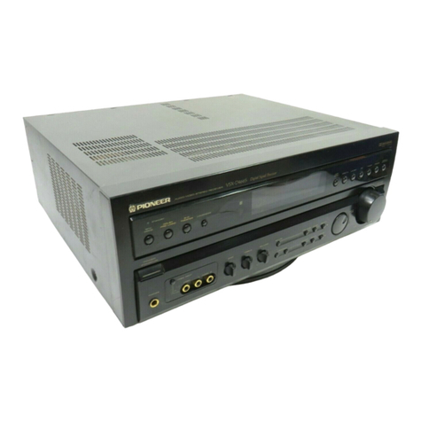
  9. Pioneer VSX-3300 User manual

Pioneer VSX-3300 User manual

)
PIONEER’
:
The
future
of
sound
and
vision.
Service
ORDER
NO.
ARP1530
AUDIO,
VIDEO
STEREO
RECEIVER.
MODELS
VSX-—3300
AND
VSX-3300S
HAVE
FIVE
VERSIONS
:
Applicable
model
a
oe
Type
Power:
requirement
_
Export
destination
VSX-
3300
|
VSX-33008_
i
aC
Rae
ae
;
|svc}
o
[|
-
|
ACL10V,120
—
127V.220V,240V
(switchable)
JUsMiitry
=
a
*
Change
the
primary
wiring
of
power
transformer.
eThis
manual
is
applicable
to
the
VSX-—3300/KUC
and
SD/G
types.
eFor
the
VSX-—3300/SD/G
type,
refer
to
page
26.
.
eFor
the
other
types,
refer
to
additional
service
manual.
@Ce
manuel
pour
le
service
comprend
les
explications
en
frangais
de
réglage.
eEste
manual
de
servicio
trata
del
método
ajuste
escrito
en
espafiol.
CONTENTS
|
1.
SAFETY
INFORMATION
-ssesssssssereetsscnscnesesesnene
2
7.
ELECTRICAL
PARTS
LIST
ccor-s+esssessesstreseeeeees
20)
2.
EXPLODED
VIEWS
AND
PARTS
LIST
+:
3
Bo
IC
IMFORMATION
srssssssserseecerseneeserereneesseearens
24
3.
PACKING
rrrretertsseeserstrensettsnssssasesceneeratsststnesesens
G
9.
FOR
VSX—-3300/SD/G
TYPE
crccsssssesseeeeeees
285
4.
ADJUSTMENTS
-rccccecccccccessecesscesererursensutetserseses
6
10.
SPECIFICATIONS
ssrcesssssccecsssceenenssstsnversceenenanace
28
5.
SCHEMATIC
DIAGRAM
crs
seceseccetssreettseetneranens
7
H.
PANEL
FACILITIES
ccssssssssssecceecessesseesesssrsessonee
2Q
6.
P.C.BOARDS
CONNECTION
DIAGRAM:
="
14
PIONEER
ELECTRONIC
CORPORATION
4-1,
Meguro
1-Chome,
Meguro-ku,
Tokyo
153,
Japan
PIONEER
ELECTRONICS
SERVICE
INC.
P.O.
Box
1760,
Long
Beach,
California
$0801
U.S.A,
PIONEER
ELECTRONICS
OF
CANADA,
INC.
505
Cochrane
Drive,
Markham,
Ontario
L3R
8E3
Canada
PIONEER
ELECTRONIC
[EUROPE]
N.V.
Keetberglaan
1,
2740
Beveren,
Belgium
PIONEER
ELECTHONICS
AUSTRALIA
PTY.
LTD.
178-184
Boundary
Road,
Braeside,
Victoria
3195,
Austratia
TEL:
(03)
580-9911
iFO@
MAY.1988
Printed
in
Japan
VSX-—
3300
1.
SAFETY
INFORMATION
{FOR
USA
MODEL
ONLY)
1.
SAFETY
PRECAUTIONS
The
fotlowing
check
should
be
performed
for
the
continu-
ed
protection
of
the
customer
and
service
technician.
LEAKAGE
CURRENT
CHECK
Measure
teakage
current
to
a
known
earth
ground
(water
pipe,
conduit,
etc.)
by
connecting
a
leakage
current
tester
such
as
Simpson
Madel
229-2
or
equivalent
between
the
earth
ground
and
ali
exposed
metal
parts
of
the
appliance
(input/
output
terminals,
screwheads,
metal
overlays,
contro!
shaft,
etc.}.
Plug
the
AC
line
cord
of
the
appliance
directly
into
a
120V
AC
60
Hz
outlet
and
turn
the
AC
power
switch
on.
Any
current
measured
must
not
exceed
0.5
mA.
cs
Leakage
current
tester
Reading
should
not
be
above
0.5
mA
Device
under
test
Test
all
exposed
metal
surfaces
2-wite
cord
Also
iest
with
L—
piug
reversed:
+
Earth
{Using
AC
adapter
“ground
plug
as
required)
AC
Leakage
Test
=)
ANY
MEASUREMENTS
NOT
WITHIN
THE
LIMITS
OUT-
LINED
ABOVE
ARE
INDICATIVE
OF
A
POTENTIAL
SHOCK
HAZARD
AND
MUST
BE
CORRECTED
BEFORE
RETURNING
THE
APPLIANCE
TO
THE
CUSTOMER.
2.
PRODUCT
SAFETY
NOTICE
Many
electrical
and
mechanical
parts
in
the
appliance
have
special
safety
related
characteristics.
These
are
often
not
evi-
dent
from
visual
inspection
nor
the
protection
afforded
by
them
necessarily
can
be
obtained
by
using
replacement
com-
ponents
rated
for
voltage,
wattage,
etc.
Replacement
parts
which
have
these
special
safety
characteristics
are
identified
in
this
Service
Manual.
Electrical
components
having
such
features
are
identified
by
marking
with
a
A
on
the
schematics
and
on
the
parts
list
in
this
Service
Manual.
The
use
of
a
substitute
replacement
component
which
‘does
not
have
the
same
safety
characteristics
as
the
PIONEER
recommended
replacement
one,
shown
in
the
parts
list
in
this
Service
Manual,
may
create
shock,
fire,
or
other
hazards.
Product
Safety
is
continuously
under
review
and
new
in-
structions
are
issued
from
time
to
time.
For
the
latest
informa-
tion,
always
consult
the
current
PIONEER
Service
Manual.
A
subscription
te,
or
additiona!
copies
of,
PlONEER
Service
Manual!
may
be
obtained
at
a
nominal
charge
from
PIONEER.
NOTES
:
@
Parts
without
part
number
cannot
be
supplied.
@The
A
mark
found
on
some
component
parts
indicates
the
importance
of
the
safety
factor
of
the
part.
Therefore,
when
replacing,
be
sure
to
use
parts
of
identical
designation.
@For
your
parts
Stock
Control,
the
fast
moving
items
are
indicated
with
the
marks
*%*
and
x.
*k*&
GENERALLY
MOVES
FASTER
THAN
*
This
classification
shall
be
adjusted
by
each
distributor
because
it
depends
on
model
number,
temperature,
humidity,
etc.
@Parts
marked
by
“®”
are
not
always
kept
in
stock.
Their
delivery
time
may
be
longer
than
usual
or
they
may
be
unavailable.
Parts
List
Mark
_No._
Part
No.
Description
Mark
_No._
Part
No.
Description
1
AWZ1677
COMPLEX
assembly
34
BBTS0PO80FZK
Screw
Ak*
2
2SA1302
Q3,Q04
35
BBZ26PO80FMC
Screw
Akk
3
2SC38281
Q1,Q2
386
BPZ30PO80FZK
Screw
A
4
ATS1135
Power
transformer
(T1)
37
NK70FUC
Nut
A
5
AKP-515
AC
outlet
(3P)
38
VMZ30PO60FCU
Screw
(AKP
-
504)
39
AWZ1678
CONTROL
assembly
Ak*
6
AEK-121
Fuse
(1.6A/125V,FU3,FU4)
40
AKR-038
Fuse
holder
Ak*k
7
AEK-
304
Fuse
(8A/125V,FU1)
41
AKX-507
Voltage
selector
1
(S2)
8
AEC-~-784
Leg
assembly
42
ASH-004
Slide
switch
9
AABI010
Rotary
knob
(BALANCE)
(CHANNEL
STEP)
(S3)
10
AABI1056
Rotary
knob
(BOLUME)
a
43
VMZ26P040FZK
Screw
11
AAD1152
Knob
(POWER)
44
AKX1004
Voltage
selector
2
(S4)
12
AAD1162
Knob
(SURROUND)
45
AEK-125
Fuse
(4A,FU2)
13
AAD1295
Knob
(SPEAKERS)
46
01g
oie
14
AAD1296
Knob
array
(TAPE2,/DAT,
47
AEB-236
Rubber
washer
VCR/TAPE1,
VDP/CDV,
48
AEB1063
Spacer
ring
CD,
TUNER,
PHONO)
101
SP
SWITCH
assembly
15
AAK1437
FL
filter
102
SP
TERMINAL
assembly
16
AAK1438
Sheet
panel
103
POWER
SW
assembly
17
AAM-030
Name
plate
104
RELAY
assembly
18
AMBi1336
Panel
base
105
VR
assembly
19
ANB1169
Front
panel
106
VIDEO
assembly
20
AZN1466
Bonnet
107
LED
assembly
21
ABH1034
Coil
spring
B
108
Terminal
(GND)
22
AEEI014
Mica
sheet
109
Chassis
23
ABA-297
Screw
110
Rear
panel
24
ABA-298
Screw
(3
X
8)
111
Bottom
plate
25
ABAI1004
Screw
112
Transformer
frame
26
ABAI1009
Screw
(3
x6)
113
Transformer
holder
27
ABAIOI1
Screw
(8
X
6)
114
Plate
28
ABA1047
Screw
115
Heat
sink
29
ABA1052
Screw
(3
x
12)
116
Binder
380
ABA1054
Screw
(3
X
10)
117
PCB
support
81
ABN-065
Nut
118
TRANS
assembly
A
32
ADG1031
AC
power
cord
(ADG1001)
,
33
ADX1191
Lead
wire
Parts
List
Mark
_No._
Part
No.
Description
1
AEA1002
Antenna
set
2
ARB1097
Operating
instructions
(English)
3
AXD1051
Remote
control
unit
4
AHAI015
Front
rear
pad
5
AHD1348
Packing
case
51
Packing
sheet
52
Battery
53
Accessory
bag
4.
ADJUSTMENTS
@
This
adjustment
procedure
is
for
only
the
adjustment
(FM
tuner
adjustment
Step
2)
which
is
differennt
from
that
for
the
SX-2300/KUC
type.
For
all
other
adjustments,
refer
to
the
SX-2300/KUC
type
service
manual
(ARP1477).
FM
SG
[FM
SG
(ikHz,+
75kHz
deviation)
|
[FM
SG
(ikHz,+
75kHz
deviation)
|
75kHz
deviation)
VSX-—
3300
Frequency
ee
Adjustment
procedure
98.0MHz
30
to
40
4B
|
98.0MHz
fies
Adjust
DC
voltage
between
IC101
13
pin
and
ground
at
maximum.
TC102@9
T102
rT]
TC101
1101
10201
SS)
iS
Ply
L102
=—
1103
icto2
JPA
Tp4e
1C101
C4
ea
a
pTP3
oy
7
«PB
vriot
tP2
TM)
on
(VCO)
1
|
2
|
3
|
4
5
|
6
L
2.
EXPLODED
VIEWS
AND
PARTS
LIST
NOTES
:
@
Parts
witho
@The
A.
mark
replacing,
be
@For
your
pa
*&k*&
GENER,
This
classific
@Parts
marke
:
;
SD/G
TYPE
|
5
:
Parts
List
ONLY
124
ZA
Sa
Ro
Ae"
OSA
Mark
_No.
y
i
Hu
Y
_
s
Akk
Akk
A
A
or
wn
re
Atk
6
Ake
7
8
7
8
9
!
10
11
|
12
'G:
AWZ1908
.
:
SP
SWITCH
ASSEMBLY
SP
TERMINAL
ASSEMBLY
JC:
AWZ1678
-
ed
SS
wT
2
ee
-
aed
——
|
AE
iT
V70r
-
-_
oo
PEEEOmACE
on
SP-A
sP-B
SURROUND
Se5i-t
S851-2
$a52
1
SUJSLXXS
ASGION?
u3
(+)
—,
os,
—
— —
—
Ll
A
Trt
RY
A
kHz
Q701
:
OFFSET
yi
fil
Al
AI
tl
M
i
tl
tl
bl fi
epoA
r
3
a
pI
i
wt
tol
CENA
oem
gd
CL.
LE
Lome
:
eros
a
‘auises
1:27}
0.047
a7oe
a7os
:
‘O7O7
#
IND
ON/OFF
10
eer
om
SURO
[SURROUND]
[TAPEZ]
tunen
5M,
STATION
[maven]
+
cro6
fsse52
R7OV
RIS
ON
OFF
VIDEO
SIGNAL
srp.
gy
_!
fl
100
pro
yisg
B
ia
SUMILATED
SELECTOR
TUNING
{7}
[TF
ch
i
0
R702
1702,
C701
STEREO
vpP
vcr
STEREO
AUTO
=
t
Sor,
100k
33p
a.
X704
$=
33p
_
Halal
ee
eee
er
:
a
706,
s
sg8
BE
4
a
Jé
RBS6
AKE-
HT
ROSiesa2
-Q705,706
:
of@too-
NG
a
Tuvce
DATA
CONTROL
SZREREEE
on
6?
mv/
8A
arizwi
a
geEREES
co
aie
:
:
COMPUTER
=
Rasa
f
&
eeoesne
5
OFF
RESt
:
[Jreoves
AR
Ham
Aa
Faw
4
5
=
-
ise
Sane
Fi
ias|
-
'
g
at
Ee
=
-=
=e
10401,402
:
GRAPHIC
IUALIZER
GRAPHIC
EQUALIZER
£0
Yona
3302
tkHz
Mz
Oke
R722
6.8K
COMPLEX
ASSEMBLY
CONTROL,
ASSEMBLY
VR403
—VR407:
30k
x2
RNI2Z03
C740,
709
F102.103
:
ATF-126
$701-727,729
:
ASG-711
F104
1
ATF-
208
7
ACSIO16
330p
330p
VR
ASSEMBLY
(272)
L101.105.106,108-
110
:
LAU2R2M
vedo
407
1
ACUIOZ
J
Cy
2
PRCA
4102
2
ATB-114
v701
1
AAV1051
(2/2)
¥i2/2)
103
ATE-079
x70?
1
ASS1004
ry
ry
STEREO
(123)
2704
eit
-
Ic
931
TAT291S
Lod
LTAAT2S
6
>
>
STOP
VOLUMI
L107
2
ATC1003.
ste
pate
|
Naa
RNIZ03
B
Motor
eH
arcton
RELAY
ASSEMBLY
a”
>
:
mare
tot
ace
Au
me
Sa
ws
ATH1004
hf
[|
ss
eo
—
IN2
VCC
OUT2
NC
GND
VS
OUT! VREF
INt
LED
ASSEMBLY
Tot
aoes
a
2
aCG1003
:
+.
AM
1
Q704
|
SS.
ON/OFF
t
2
eS
om
T102
1
ATB-095
:
ot
rel
ae
A
ees
AELIOS3
.
01
t
GS06607
=
AcHtOee
tes
eras
+
ACG1003
:
t
ce17
:
ACHION!
VRQ51
+
ACX1010
k
eee
ASR-112
33,534:
ACN-
139
Qrio
|
Rett
ACN
09
1,
RESISTORS
:
ora
PCNI4
CN15
tVvoLUME)
i]
VAIO}
:
VRTBBVS472
Indicated
in
Q,
1/4W,
1/6W
and
1/8W.
+5%
tolerance
IND.
fo]
101
+
ASS1005
unless
otherwise
noted
k;kQ,
M;MQ,
(F);
#1%,
ve
lo
os
(G):
42%,
(K);
410%,
(M):
+
20%
tolerance.
sown
Io]
|
-
SENSOR
pa
2.
CAPACITORS
:
AXX
1005
pa
Indicated
in
capacity
(uF)
“voltage
(V)
unless
otherwise
noted
p;
pF.
Indication
without
voltage
is
SOV
except
BAZBIZL
Cen
i
electrolytic
capacitor,
951:
LED
DRIVE
scale
5
esi
-eaes
CausRex
3.
VOLTAGE,
CURRENT
:
;
;
#4
L983:
ATH~
O50
+
DC
voltage
(V)
at
no
input
signal.
2sc24se
'
t
Value
in
(}
is
DC
voltage
at
rated
power,
mA
;
DC
current
at
no
input
signal,
———S
oe
Seen
|
:
-
4,
OTHERS
:
;
'
VIDEO
ASSEMBLY
+
Signal
route.
i
a
ae
Q703,707,709,710
:
2.
ee
eee
@
;
Adjusting
point.
a
RELAY
DRIV
The
A
mark
found
on
some
component
parts
indicates
the
.
Ave
importance
of
the
safety
factor
of
the
part.
Therefore,
when
220k
18S
252
|
tapiacing.,
be
sura
to
use
parts
of
identical
designation.
EE
sit
-
we
eon
ry
pe0z
oan
in
4
%
marked
capecitors
and
resistors
have
parts
numbers.
i
c——)
°
©
T
alg
Af
eer
Paeer
:
POWER
SW
ono
aI
Ley
|
issese
a
clas
This
is
the
basic
schematic
diagram,
but
the
actual
circuit
!
ASSEMBLY
SS
CD
{]
our
may
vary
due
to
improvements
in
design.
'
8
'
$728
[ot
ROIT
}
CHANNE!
"
.
.
0618
pore
i
ap
power
fi
Yee
Tel
tH
Q90s
&.
SWITCHES
:
(The
underlined
indicates
the
switch
position)
4
oc
le
See
ne es
AsH~004
100%
Sok
FM
ae
A
cI
CONTROL
Assembly
i
t
Rares
|
tree]
;
a
Seamer
Ol
1e-201
cxeee
$70)
:
TUNING
DOWN
a
i
47mF/88
t
AcHIo
i
vec
OUT
INH
IN3
GND
C2
IN2
Ct
o
1}
8
ATH
-
050
:
°G
(
;
L904
r-}
env
fooun
VDP/
CDV
‘
2?
—O-
VIDEO
IN
&)
3
R909.
R908
oa
a
330
F
zsaoass
ATO.
R550
2801845)
p50.
28
UW
-
«
2904
ee
580
ark
1s!
4
POWER
TRANSFORMER
|.
C905
4,
=)
CO,
SS
ATS
i135
1
bets
CY CY
R906
tN
‘
an
agoz2
470
one
Sma
A
™!
25C1740S
330
0604
1C601
:
TRANS
a a
a
ja
i
903
i
MZS6B2L.
REGULATOR
ASSEMBLY
F
71
fait
e910
one
VCR/
TAPE
4
\
+
cent
re
aoe
|
|
|
se
VIDEO
MEMORY
SCAN
H
[]
im
5
]
‘M
MODE
i
asciaas
:
,
180
Ot
|
3
eur:
‘M_
TUNING
i
a523
|
0509
16252
hte6or
seen
(C902
:
‘APE
_2/DAT
{
c
EC
TOMIaH
|
76
REGULATOR
Ss
i
VCR/TAPE
1
i
TO
MONITOR
TV
24:
VOP/COV
‘
te
023,524
vides
y
$725:
CD
OVER
LOAD
DET.
ats
we
pec7a.os
VIDEO
OUT
UNER
(
a
1
'HONO
i
RELAY
ASSEMBLY:
oe
W
oy
fl
:
VIDEO
SIGNAL
SELECTOR
i
-
Pe
+
8
a
POWER
SW
Assembly
f
I
Q551
:
REGULATOR
ease
Sic16
909
TO
RF
MODULATOR
S728
:
POWER
:
10/96
SP
TERMINAL
Assembly
:
”
}
D557
ATT
1044
(KU)
ug
+
605
atk
vf
RSee
Reo]
TSF]
pss
ATT
1015
(SD/G)
'
$854:
SURROUND
LEVEL
L~M-H
-
Resre
Fagse
608
ae
Am
TES:
stage
+5v(000
TS]
yg
032
foow2w
ass:
feS8d
fis.
i
oh
|
i
POWER
OFF
al
+sv
Tal
a
casaqt
&
oe
es.
a
anes
FOWE
ae
Ct
A
a7
Kits
VSX
-3300/$D/G
TYPE
.
i
OD
RYS02_
/25
3
I
I
zo
;
Jac
ey
|
R571
pac
ies
'
:
+
céix
lo
*
7
sto~120v
&
9604
4,
0.017125
dene
a0a
eyneies
i
oss8
"prey,
220~2e0v
I
Ri
ee
ns
es
D
TOTAL
128
|
FUI,2.
REK-125,
\
SELECTOR
2
oD
;
|
0553
cag3
bo
~~
ak
x1004
D
+
REOZ
tL
3
ac
tz20v
ip
—
on
ee
AC
OUTLET
Leas
604
Tr
o808
B2Ki2W)
——O-
60
Hz
S176
TYPE
SWITCHED
ue
TPE
ONLY
|
acitov
|
.
boatman
tine
t
eeeneaimeiahaanemtaniendl
oe
r
ee
1
as
A
——as
a
-
a
220¥
3:
DC
DET.
wren
@
AC
CUTLETS
AC
POWER
coRD
een
2emausew)
|
AKP
~
SIS
ADG
1031
ADG
i001)
¢
KUC
TYPE?)
a
50/60Hz
te
{AKP
504)
ADG
1015
(SOAGTYPE
)
{
ACN~209
1
A
(kuc
ONLY)
'
SZ°
VOLTAGE
SELECTOR
¢
Fut
cont
at
=O
A
AKX—507
4a
0.01
COMPLEX
ASSEMBLY.
A
A
ST
A
EE
TS
CAWZ
1907)
VSX—
3300
4
5.
SCHEMATIC
DIAGRAM
SD/G
:
AWZ1S07
SD/G:
AW21908
TR2
TR:
Tea
TPS
‘
COMPLEX
ASSEMBLY
KUC:
AWZ
1677
S.METER
—TMETER
TL.WETER
veo
CONTROL
ASSEMBLY
._KUC:
AWZ1678
e
6
eS
OS
ee
-_
7
a
a
OQ
ee
eo
©)
nial
=
-.
-
0102
:
MIXER
Q103
:
RF
AMP
<
<
4
v
vR403—a07
2102
§
101:
RF
AMP
ain
cx6
=
ascz7Bee
HOS
Br
'
2sK2ar
..
i
late
Raia
R14:
Evy
6105
FH
ipio2
i¢
SOK
im
prot
350
|
Rusvia7
!
et
Ae
j
Isvia?
tt
ANTENNA
eR
ibe
10a
Lf
re
33/30
|
H
rs
MSZIGPF
Ds
5ma
:
="
ha]
gi9e
ice
VR
ASSEMBLY
(1/2)
=
[3
ns
ZR06
r.
RI36
we
C135,
bras
47k
-
—
<4
|
BAL
193
47
ae
27k
JT
10750
sg,
6
soho
VR95I:
VOLUME
tT]
300n
ACK
1010
FM
RST
theisa
R140
353
anes
106
:
FM
+B
"
Lungat
1G
ag
Tee
OOP
SwrTcHING
=
cies
[ex
4
20/20.
oe
47/50
7TSQ
ci2i
2.2uH
“tp
a
6no|
©
0.022
Th)
Q104
:
OSC
RIOS
RII2
9106
am
|
O
ee
z20F
fiozy)
Anazpl
1c1oz
AN7a70P
25c2668
QO
cee
0.01
© «
re
b
ule
2
Em
fag
P)
=
{lye
we
33
i102
:
i
2
Fe
25
MIXER
BALANCE
cit
Ree
cnr
8
we
Eat
5°
5p
5.1k
Fi5p
i
oI
2.
St
1C401,402
:
6
BV
ae
GRAPHIC
By
0103
104:
SvC3zic2
Fl
EQUALIZER
GRAPHIC
EQUALIZER
i
(SVC
321D2r
Q105
;
BUFFER
Ul
(OH
33eH2
1OKHz
|
Mr
4i
F
RI2z0
|
pos
RIGO
ra
eal
fea]
fe
5
Seq
VR403
—VR407:
30k
x2
7
7
Era
Ral
ets
Sy]
(Baas
C403
|
PRE
AMP
cue
ge
zal
|Ea|
[e288]
|e
Seo
0.01
Te10z
32
Fed
zy
le"gs
g2fo)
3
32
83>
Lio2
+
AW
T
+
i
amoral
R21
o
a)
'
cr7s,
47k
=
p104
639,
3
|
8
0.022
Toor
cus
J
4
28
E
@
p
cise
RI30
5g
3
10/50
470
a5
&
3
«
aS
owt
a
+
RIS)
7
en
Stk
Tose
15009
PHASE
DETECTOR
Qu0
nie
CHARGE
PUMP
esc24se
75K
1
Ris2
i
BA30I2L
TP
1
af
cia
\
|
]
18252
‘or
ee
=<
eoigey
cat4
9109
RIS
RSS
F°-32,
c183:12000,
Beale.
RN2Z20l
+l
ce
67k
4.7K
Cee
ore
com
ee
ee
ue
0109:
AM
+B
Paves
BOLO
TE
¥
neio
i]
SWITCHING
3s
4
bo
1103
Ri
emeemmed
E)
3
LM7oo1
1103
:
PLL
Wie
37
folks
2
22en
.
eee
eee
eee
eee
;
ES
EEE
2
!
201,202
:
BUFFER
osie
z
cr
PLAY
IN
=e
|G
f
women)
|
P
TAPE
2
bat
Recut,
|
@
WOmvV
/2.
2k
Q501
~512,515-518.01~4
POWER
AMP.
PLAY
IN
,
(
150mV/5OKR
A520,
pa
a
10005388
or
i
/
TAPEt
REC
OUT
2S5A1145
a
1502
wh
'
—
{
1SOmv/
2.20
50
i
Qs28
[[somw7e
ana]
Lsor
Pion
Toon
RESO
28c1e45]
510
47k
iss2s2
R540
1SOmV/50KN
os502
sig.
22
Le
2sa992
2sa992
Low
1CBOI1/2)
%
co
Mszige
R514
sn
1SOmV/
50kKQ.
C33
620
R544
534%
<=
ae
2.2/50
LSKUEI%)
asia
0.33x2
st
H
=
A)
PHONO
Resiz
XC)
escasos
100/16
R546,
R546
28C1845
peemv
conc]
R309
ASH
10k
750
0809
Iss252
cole
2504
So/
Sedaitos
c309
cali
escieas
500
523
524
:
L.-
C316
0.047
2400p
82000
Gees
1)
3208
705
«)
'
+
OVER
LOAD
DET.
_——
*
R510
an
R306
3
SE
c306
e310
cae
i
832 pital
—_
phe
;
]
4
|
rm
PHONO
ame
|
R304
ey
Rs09
RBII
R521
4
;
C
;
(7
T
7
25mVv/50KR
C302
0501
(©
)os07
coat
i
:
+
+
az
}
RosTe
ZR558
R323
SIMULATED
0503
csi?
:
|
10%,
0605
:
a
g
STEREO
L
Arse
‘
R6oe R609
POWEF
s5Omv
/50kK0.
_—
I
Lekuw)
B2k
606
MUTE
ach
VOR
/¢DV
REGS
=
SRSA7
I
escis
Soon
AUDIO
IN
R324
csi!
(7
'
Bonv
son}
|
QD
:
e503
R503
|
R507
c509
+
«)
a517
i
RISO!
abe
pac
l
9891,
RS4a3
100
6}
e:
i
—
!
REIS
a
Rec our
|
@%
eh
50)
Some
Suh are
©)
>
i
Cp
7
TCSt6GN
4.8mA
‘ae
Ae
R326
seo
tiebe
a?
aa
cea
a
R539
F
SRsa1
eerooe
CD
ceo4
AY
jcei8
Gere
R604
BrC6O3
+
eet
sTAPES
pLay
in
{C201
:
FUNCTION
R523
Hoaie
oat
ee
Bek
47ers
ca
y|$
we
SELECTOR
Ar)
92°2
1SOmV/50kN.
SRST
Ww
“J
ICBOII72)
c505
cso7
css
R38
MS216PF
RS35
(7
Q604
:
RELAY
DRIVE
Q601.602,.606
:
DC
DET.
cial
nec our
|
me
K)
0505
t+
[SOmv
/2.2k0
0508
;
csi
LRS63
8105
ceoe
p6é0o9;
TAPE
2
R338
5
S03,
a
m
a
Bar:
PLAY
IN
R326
we
woores
ROIZEB
f
f
1SOmV/
5OkKN
@
4,2
28c3281
rev
03,4
28a1302
A
SS
A
SS
SS
SS
SS
i
SRT
O10
»>
VOID
}
€01d!
g0!1D
POWER
SW
\SSEMBLY
VIDEO
ASSEMBLY
VDP/CDV
VIDEO
IN
SYR, IND.
8
9
10
11
NOTE
1,
This
P.C.B
connection
diagram
is
viewed
from
the
parts
mounted
side.
2.
The
parts
which
have
been
mounted
on
the
board
can
be
replaced
with
those
shown
with
the
corresponding
wiring
symbols
listed
in
the
following
Table.
P.C.B.
pattern
diagram
indication
Corresponding
part
symbol
70504.
EO
oOo
90
or
Transistor
iE
—
Radiator
type
transistor
p203
—
0203
©
°
o—}q——0
Diode
Others
P.C.B.
pattern
diagram
indication
Part
Name
Ic
Ic
os
2
49
VSX
—3300
VIDEO
OUT
Variable
resistor
or
VCR/TAPE1
f
}
.
ahs
Semi-fixed
resistor
—
VIDEO
—
TO TO
RF
CONTROL
out
IN
MONITOR
TV
MODULATOR
OUT
IN
3.
The
capacitor
terminal
marked
with@)idouble
circles)
shows
negative
terminal.
4,
The
diode
terminal
marked
with
©)
(double
circles)
shows
cathode
side.
5.
The
transistor
terminal
to
which
E
is
affixed
shows
the
emitter.
o-ffto
Capacitor
(Polarity)
Capacitor
(Non-polarity)
VR
ASSEMBLY
LED
ASSEMBLY
-y
VIDEO
SIGNAL
LECTGR®
Q708
a70og
Q703
a7o7T aQ7io
Q701
gow
VR403 VR404
VR405
VR406
VR407
VR401
1C701
IC402
{C401
1C403
Q704
Q706
Q705
SD/G
:
AWZ1908
CONTROL
ASSEMBLY
KUC
:
AWZ1678
|
SD/G
TYPE
+
O
|
i
ome,
io)
|
i
s3
CHANNEL
|
|
STEP
I
FM
50k—100k
!
AM
9k
—
10k
Oe
ees
ic
12
i
I
2
3
I
4
|
5
6
P.C.
BOARDS
CONNECTION
DIAGRAM
y080
zosO
=
91S0
20891
zozD
1020
L010
SD/G
:
AWZ1907
2080
9080
ZOSO
POSO
SISO
10SD
ZOLO
==
SOLO.
LOLO
FOLD
:
1090
O1g
g0sD
10891
GOSD
«EOS LOE! 8010
COMPLEX
ASSEMBLY
KUC
:
AWZ1677
10991
g090_
PZSO
€zso
z1so
60S
20S0
11S0
10291
ZOLD
§=—-OLID
1010}
=
E010
E019}
g010
LOLA
Z0IOL
1OlOL
TAPE
f2/DAT
VCR/TAPE1
j
——
FM
—y
AC120V
60Hz
AS21-V8
nig
OSH
oy
ae
9.90330
9.0
ore
ge
:
began
S
“sign
‘i
EA,
IMO
ey
«
9006550
0
0)
yo
age”
Bienes
ce)
a
6+—-——'
TRANS
ASSEMBLY
SD/G
TYPE
[110
—120v
|
4
O
220
~
240V
|
|
_1_
|
A
S4
VOLTAGE
SELECTOR
2
Lt
eee
aes,
eee
SP
SWITCH
ASSEMBLY
POWER
SW
ASSEMBLY
RELAY
ASSEMBLY
3
a
N
|
€
S
)
: :
OeOt
6101
OS0!
OSOS
1c80S_-GRIe
~=—-CeOS
O10t
C108
C102
~—
10S
620!
Og!e
O20
G20S
OPFOR
CeDe
YO@TXWA
:
D\de
o108
Ic301
0203
=
OR02_«ICRO!
0208
=:
O210.—«Oeo
0108
1C103
6103
IC101
0110
ICIOS
ICSO}
=
OBI
~OBOA
_
0209
Oe21S
Oe8S3
oeSt
cece
Iceo)
YYa
TXWA
:
OU
YIGMaeeA
XIIIMOO
1Ci0)
1Ci05
AKIO}
=
Wi
139AT\AOV
Tasiaaat
SS
=*d
VOSTOA
sHOd
8V-1
SPA
m
sane,
Sh
one
anoe
YJGMa2eA
GUAAT
34YT
0\G2
~~
TS
VOSF=
Orn
vost
—or
VOAS
—
OSS
ai
||
|
.
: |
JOATIOV
ne
S
AOTOII32
HOTIWe
Ge
Be
ce
eee
ee
eR
|
YIGMi2eA
We
AaWOd
2
et
| |
ae
rey
oft
cn
Y_IGM322A
,
|
,
al
:
YIG@Ma2eA
YAISA
OOEE—
XeV
fe
\
r-
|
|
|
sMNAHO
€e
Q
|
gate
|
yoor
—
302
M3
1
yor—e@
MA
L
St
iY
er
a
ei
nl
St
30vO
sOTO
tt
This
P.C.B.
connection
diagram
is
viewed
from
the
foil
side.
YIGMae2eA
AV
tt
=
eninnsamunsnrennonal
{isso
EOI
Or
©
8
YJGMaeeA
O3dIV
T
TU
ONOSSIN,
fAIAT\
ADV
JOATNOS
3A
OT OT
r—
O80lV
VGO\9aV
VI_TUO__
AOTAIUGOM
_
VT
AOTIMOM
ul
TUO
Ul_O3GIV
YIGMsaeeA
G34
aORAV
ZOSAV__AOAAV
ronol
sonoi
rovol
80€
IXWA
:
O\de
8YOTXWA
:
OUA
YIEGMS22A
JOATUOD
80V0
tovo
EovO
eO0tO
Oryvo
YOO
0101
O10¥
G04
€
O108
o10e
1C103
0!
Cae
os
—
Praag,
cd
ma
he
Se
Be
A
{cia
=
i
JK
pact
=wiat®
z
LOO
68
(ol
lGidoll
We
AIWOF
Y_JaMa22A
External
Appearance
of
Transistors
and
ICs
AN7470P
LAt265S
M5201P
LM7061
a
FCSt64N
»PC78M12H
2841115
2802603
15
2a
Type
Na
1
AALLRALALIA
LI,
,,
Lot
No.
Aq
Hh
rleely
H
ht
H
ii
Are
£
lle
2SA992
28C2458
2SC2668
2801845
2SA933S
2801
740S
Type
No
Lot
No
hre
Lot
Ne
Typs
No
Type
No
fre
—Lot
No
hee
=
—E
“.
? ¢
8
Bé
a
2S5K246
BA3812L
TA7291S
CX-
894
Type
No
loss’
4
5
oh
9
28A1302
2863281
Lot
No
Type
No
Type
No
FE
bre
E c
7
8
m™
VSX—3300
RN2201
M5218P
M5218PF
RN1203
RN2203
RN1201
Fs
Typa
No
4 3
Lot
No
€
€
.
2S8A1145
2SA968
2802705
2802238
2802878
2SC2786
pPC78L05
Type
No
Lat
No
VSX—3300
7.
ELECTRICAL
PARTS
LIST
NOTES
:
@
Parts
without
part
number
cannot
be
supplied.
@
Parts
marked
by
“@”
are
not
always
kept
in
stock.
Their
delivery
time
may
be
longer
than
usual
or
they
may
be
unavailable.
e@The
Amark
found
on
some
component
parts
indicates
the
importance
of
the
safety
factor
of
the
part.
Therefore,
when
replacing,
be
sure
to
use
parts
of
identical
designation.
@For
your
parts
Stock
Control,
the
fast
moving
items
are
indicated
with
the
marks
*k*
and
x.
tke&
GENERALLY
MOVES
FASTER
THAN
&
This
classification
shall
be
adjusted
by
each
distributor
because
it
depends
on
model
number,
temperature,
humidity,
ete.
@
When
ordering
resistors,
first
convert
resistance
values
into
code
form
as
shown
in
the
following
examples.
Ex.1
When
there
are
2
effective
digits
(any
digit
apart
from
0),
such
as
560
ohm
and
47k
ohm
(tolerance
is
shown
by
J=5%,
and
K=10%),
560
956
x
10'
>561
-
Svevaceeucsees
+
RD1/4PS
airiah
47k
247
x
108
Pies
seseserneeceeerersseressesecoseees
RD
/
APS
1417
][3]
J
O.5QS0RS
vee
Maieocbebeesauuretuasesseachbasae®
-
RN2H(O}[R!
12010.
sees
”
RSIPOLTOTK
Ex.2
When
there
are
3
bfactive
its
(such
as
in
nigh
proceron
metal
film
resistors).
§.62k
2-+562
x
10'
>
5621
-
Miscellaneous
Parts
-
RN1/4SR{56/2Z/0]F
‘VIDEO
Assembly
P.C,
BOARD
ASSEMBLIES
SEMICONDUCTORS
Mark.
Symbol
&
Description
Part
No.
Mark
Symbol
&
Dascription
Part
No.
LED
assembly
te
10901
:
CX-894
VIDEO.
assembly
%*&%*&
10902
HPC7T8LOB
COMPLEX
assembly
AWZ1677
xk
Q903_
RNi201
POWER
SW
assembly
wk
=Q901,E904
25A933S
CONTROL
assembly
AWZ1678
tek
§Q902,Q905
28C1740S
.
Sle
%
D901,D902
1$8252
RELAY
assembly
COIL
:
SP
TERMINAL
assembly
.
VR
assembly
Mark
Symbo!
&
Description
Part
No.
SP
SWITCH
assembly
TRANS
assembly
L901
Inductor
ATH-
050
OTHERS
CAPACITORS
Mark
Symbol
&
Description
Part
No.
Mark
Symbol
&
Description
Part
No.
Akk
8,04
2SA1802
904
CCCSL270550
Akk&
91,92
28C3281
C909
CEAS100M25
A.
*
Tl
Power
transformer
.
ATS1135
C905
CEAS102M16
Avxk*
FU3,FU4
Fuse
(1.64/125V)
AEK-
121
C903
CEAS221M16
Ake*&
FU1
Fuse
(8A/125V)
AEK-
304
C906
CEAS222M16
€901,C902,C908
CEAS470M16
A
3P
AC
outlet
AKP-6515
;
‘(AKP-
504)
RESISTORS
A
AC
power
cord
ADG1031
Mark.
Symbol
&
Description
Part
No.
(ADG1001)
RSog
RD1/2PM331)
R904,R905
RD1/4PM121J
LED
Assembly
Other
resistors
RD1/8PMoog)
OTHERS
SEMICONDUCTOR
Mark
Symbol
&
Description
Part
No.
Mark.
Symbol
&
Description
Part
No.
1P
Pin
jack
AKBI1010
*
D951
AEL1053
3P
Pin
jack
AKB1050
;
2P
Mini
jack
AKN1006
CAPACITOR
. ;
5P
DIN
socket
AKP-
081
Mark
Symbol
&
Description
_
PartNo.
C957
’
CKDYF103Z50
COMPLEX
Assembly
(AWZ1677)
SEMICONDUCTORS
Mark
Symbol
&
Description
C102
1C101
1C1603
IC802
IC301
IC801
iC201
IC601
Q606
Q505,Q506
Q108Q108
Q511,Q512
Q501,9502,0515,Q516
Q503,0504,0523,Q524,Q601,0602,
Q604
Q509,Q510
Q107,Q110,Q201,Q202
Q517,Q518
Q103,Q104
Q507,Q508
Q102
Q605
Q101,Q105
Q108
D604
D603
D609,D610
D608
D103,D104
D601,
D602
D105
—
D109,D501
—
D510,D617,
D618
D101,D102,D110
RELAY
Mark
**
Symbol
&
Description
RY5O1
Relay
.
Part No.
AN7470P
LA12655
LM7001
-
M5201P
Mo5218P
M5218PF
TCOLS4N
#PC7T8M12H
2SA1115
2SA1145
RN2201
28A968
25
A992
28C1845
28C2238
25C2458
25C2803
25C2668
28C2705
25C2786
28SC2878
2SK2A1
2SK246
-
HZS6B2L
RBV602
RD12EB
RD27EB
SVC321C2
(SVC321D2)
35566
188252
18V147
Part
No.
ASR-
112
COILS,
FILTERS
AND
TRANSFORMERS
Mark
‘Symbol
&
Description
Li02
AM
OSC
coil
Lill
FM
coil
L112
FM
coil
_
L107
FM
coil
L103
FM
detector
coil
L501,L502
AF
choke
coil
L101,L105,L106,L108
—
L110
Axial
inductor
L104
Inductor
F102,F103
FM
ceramic
filter
Part
No.
ATB-114
ATC1001
ATC1002
ATC1003
ATE-079
ATH1004
LAU2R2M
LTA472J
ATF
-
126
Mark
Symbol
&
Description
'
F104
AM
ceramic
filter
Ti0z2
AM
antenna
transformer
T103
FM
RF
transformer
T101
FM
matching
transformer
CAPACITORS
Mark
A
Symbol
&
Description
TC101,TC102
Ceramic
trimmer
céll
(0.01
/
125V)
C617
(47mF
/5.5V)
C606,C607
(8200/63V)
C517,C518
C519
—
C522
C128,C303,C304,C509,C510
C119,C515,C516
C113
€121,C117,C142,C143
C112
C102
€101,C104,C105
C116
C106
€107,C505,C506
C163,C507.C508
C114
C150
C616
C156
C146"
C131
C130
C160
C135,C139,C149,C165,C168,C609,
C612
,
C511,C512,C604
C602
C608
C605
C134,C161,C162,C201,C202,C301,
C302,C313,C814,C501,C502,C523,
C524,C801
C136,C158
C144
C137,C804
€151,C305,C306
C601
C603
C133
C503,C504
€154,C155
C315,C803
VSX—
3300
Part
No.
ATF
-
208
ATB-095
ATC-
194°
ATE-063
Part
No.
ACM
-
015
ACG1003
ACHI1011
ACH1044
CCCSLO50C500
CCCSL101K500
CCCSL221550
CCDCHO70D50
CCDCHO80D50
CCDCH150J50
CCDCH330I50
CCDRH390J50
CCDRH330IJ50
CCDSLO10C50
CCDSLO20C50
CCDSL101550
CCDSLA70J50
CCDTH180J50
CEANP100M50
CEANP4R7M50
CEJAR22M50
’
CEASR47M50
CEASORIM50
CEJAQ1LOM50
CEAS1R5M50
CEAS100M50
'
CEASIOIM16
CEAS101M25
CEAS102M35
CEAS2R2M100
CEAS2R2M60
CEAS3R3M50
CEAS330M16
CEAS4R7M50
CEAS470M25
CEAS470M85
CEAS471M6
CKCYB472K50
CKDYB102K50
CKDYB272K50
CKDYB831K50
VSX
—
3300
Mark
Symbol
&
Description
C103,C108,C118,C122,C123,C128,
C141,C145,C147,C148,
‘C186
—
C168,C170,C204,C205,
C307,C308,C618,C805,C806
€121,C140,C175
C124,C125,C138,C187,C164,C173,
C203,C316
C126,C171,C17Z
€162,C153
C309,C310
C802
C525,C526
C132
C311,C312
C120
C159
RESISTORS
Mark
Symbol
&
Description
¥%
VRIO1
Semi-fixed
(4.7k2Q)
R533,R534
(0.33
x
2)
R611
(2.2M/1/2W)
E>
B
PP
BP
R519,R520
R627,R528,R537,R538,R549,
RS550,R553
—
R556
R307
—
R312,R513
—
R516,K535,
R536,R571,R613
R511,R512,R615
R521
—
R526
R543,R544
R607
R60B
R601,R602
Other
resistors
OTHERS
Mark_
Symbol
&
Description
*
POWER
SW
Assembly
X101
Crystal
resonator
4P
Terminal
(ANTENNA)
4P
Pin
jack
‘
6P
Pin
jack
SWITCH
Mark
kk
$728
Tact
switch
(POWER)
Symbol
&
Description
Part
No.
CKDYF103Z50
CKDYF223250
CKDYF473Z50
CKDYX473M25
CQMA152K50
CQMA242350
CQMA332K50
CQMA473K50
CQMA683I50
CQMA822J50
CQSA431350
CQSA471I50
Part
No,
VRTB6VS472
ACN
-
138
ACN
-
209
RD1 /
4PMF680J
RD1/4PMF
O00]
RD1/4PMQOou!
RFA1/4PS
O00
J
RFA1/4PS101J
RN1/4PQI501F
RSILMF472J
RSIPMF182]
RS2LMF
OOD
J
RD1/8PMoOO00I
Part
No.
ASS1005
AKA1009
AKB1007
AKB1024
Part
No.
ASG-711
CONTROL
Assembly
(AWZ1678)
SEMICONDUCTORS
Mark
Symbol
&
Description
-
ww
=
1C401,1C402
¥&k
C403
*%*&
IC701
xk
=Q708
wk
=
Q709
*%
D708
%
D701,D704,D707,D708,D710
SWITCHES
%*k&
Q701,Q703
—
Q706,0710
Q707
Mark
Symbol
&
Description
wx
S701
—$727,8729
Tact
switch
TUNING
(UP,DOWN),
FM,
AM,
1/13-—12/24,
VIDEO
SIGNAL
SELECTOR,
MEMORY,
MEMORY
SCAN,
FM
MODE,
FM
TUNING,
-
TAPE
2/DAT,
VCR/TAPE
1,
VDP/CDY,
CD,
TUNER,
PHONO,
SIMULATED
STEREO
CAPACITORS
Mark
Symbol
&
Description
C437,C438
C701,0702
C704
C431
C703
C405,C406,C706
C411,C433
C403
C427,C428
C432
C412,C434
C415,C416
C407,C408,C708,C7
10
C413,C414
C435,C436,C708,C713,C714
C707.
Cili
C425,C426
A21,C422
CA17,C418
C429,C430
C423,C424
C419,C420
C404
RESISTORS
Mark
Symbol
&
Description
.
%
VR401
Variable
resistor
(500k)
(BALANCE)
%
=
VR403
—
VR407
Variable
resistor
(20k)
(GRAPHIC
EQUALIZER)
Other
resistors
Part_No.
BA3812L
M5218PF
PDG023-
A
RN1203
RN2201
RN2203
28C2458
RD5.1ESB2
188252
Part
No.
ASG-711
.
Part_No.
CCCSL220550
CCDCH330J50
CEJA4R7M50
CEASR68M50
CEJAG10M50
CEJAi01M10
CEAS4R7M50
CEAS470M25
CEJAR22M50
°
CEASR68M50
CEJA4R7M35
©
CKDYB122K50
CKDYB331K50
CKDYB391K50
CKDYF103250
-
CKDYF473Z50
CKDYX473M25
CQMA123K50
CQMA223K50
CQMA392K50
CQMA393K50
CQMA682K50
CQMA683K50
CEJA470M16
Part
No.
ACS1016
ACU1023
RD1/8PMOOOJ
VSX
-—3300
VR
Assembly
OTHERS
SEMICONDUCTORS
Mark
Symbol
&
Description
Part
No.
Mark
_
Symbol
&
Description
Part
No
%
‘V701
Fluorescent
indicator
tube
AAV1051
tk
1C951
TAT291S
&
=X701
Ceramic
resonator
ASS1004
k*
=
Q951
RN1201
Remote
control
sensor
unit
AXX1005
COILS
; ;
Mark
Symbol
&
Description
0
Part
No.
RELAY
Assembly
L963
Inductor
(100¢H)
ATH-~
050
L951,L952
Axial
induct
LAUSR6K
SEMICONDUCTORS
pret.
Mark.
Symbol
&
Description
Part
No.
CAPACITORS
vs
Mark
Symbol
&
Description
Part
No.
kk
0551
2SC3377
%
D555
RD6.2ESB3
C953,C954
CEAS4R7MB50
%
D551
—
D554
$5566
C955,C956
CEAS470M25
%
D556
—
D559
188252
C951,C952
CKDYX473M25
RELAY
RESISTORS
Mark.
Symbol!
&
Description
Part
No.
Mark
Symbol
&
Description
Part
No.
kk
RY502
Relay
ASR1012
%*
VR951
ACX1010
.
Variable
resistor
with
motor
Mark.
Symbol
&
Description
Part
No.
R953
RD1/4PM471J
Other
resistors
RD1/8PMOOO]
%
T551
Power
transformer
ATTI011
F
CAPACITORS
SP
SWITCH
Assembly
Mark
Symbol
&
Description
Part
No.
C1
(0.01/125V)
ACG1003
SWITCHES
C551,C554
CEAS470M25
Mark
Symbol
&
Description
Part
No.
C552
CEAS471M25
C853
CKDYF103Z50
“%&%&
$852
Push
switch
(SURROUND)
ASG1017
RESISTORS
| .
*%
S851
Push
switch
(SPEAKERS)
SUJS5LXXS
Mark
Symbol
&
Description
Part
No.
RESISTORS
Mark
Symbol
&
Description
Part
No.
R568,R569
RD1/2PMF
OOO
J
;
R576
RD1/8PM1823
A
R851,R852
RS2PMF331i
OTHERS
SP
TERMINAL
Assembly
Mark
Symbol
&
Description
Part
No.
SWITCH
;
Phone
jack
(PHONES)
.
AKN1002
Mark
Symbol
&
Description
Part
No.
TRANS
Assembly
tek
S854
Slide
switch
ASH1003
(SURROUND
LEVEL)
There
is
not
supplied
parts
in
this
assembly.
RESISTORS
Mark
Symbol
&
Description
_Part
No.
A
R856,R857
RS2LMF
OOO
J
A
R854,R855
RS3LMF2R7]
OTHERS
Mark
Symbot
&
Description
Part
No.
_
8P
Terminal
(SPEAKER)
AKE-111
VSX—3300
8.
IC
INFORMATION:
PDGO023
(MICROCOMPUTER)
Terminal
BE
Sc
es
ae
ae
}
1
|
vou.
IND
|
°
|
POWER
ON
|
L_._[
VOLUME
indicator
to
go
on.
When
the
terminal
voltage
remains
low
for
mare
than
60
ns,
this
terminal
enters
the
backup
made.
.
WAKE
UP
POWER
ON
When
the
terminal
voltage
becomes
high,
this
terminal
returns
to
its
original
a
|
REMOTE
IN
|
|
REMOTE
IN
|
|
L
|
Remote
contre)
signal
input.
a
CLOCK
This
terminal
outputs
“CLOCK”
for
control
signals
directed
to
I€201
(TC9164N)
and
IC103
(LM7001).
; .
DATA
This
terminal
outputs
“DATA”
for
control
signals
directed
to
IC201
(TC9IG4N)
and
IC103
(LM7001).
,
When
the
output
of
IC102
(ANT470P)
pin
9
in
the
tuner:
unit
is
low,
this
|
6
froxes
sraneo|
1
|
BROT.
PORT.
at
terminal
causes
the
FL
display
stereo
indicator
ta
go
on.
When
the
output
of
IC101
(LA1265S)
pin
8
in
the
tuner
unit
is
low,
this
PRREe
STOP
ut
SORT
terminal
causes
the
FL
display
tuner
indicator
to
go
on,
KEY
MATRIX
Detects
the
tact
switch
position.
.
aoe
Eee
OUTPUT
When
the
VIDEO
signal
is
selecting
While
a
control
signal
(DATA)
is
transmitted
to
IC103
(LM7001}
KEY
MATRIX
INPUT
Ca
[ooo
fom
o
_[»
[mea
OO
wm
Immediately
after
transmitting
DATA
to
IC201
(TC9184N)
FUNCTION
Instantaneously
becomes
high
after
transmitting
a
control
signal
to
IC
STROBE
FUNCTION
IC201
(TC9164N)
When
the
system
is
in
the
FM
“MONO”
made
When
the
SIMULATED
STEREO
is
operating
TUNER
AUTO
MONO
SIMULATED
STZREO
When
the
VOLUME
contre]
is
operating
a
This
is
power
supply
terminal
for
a
resistor
(incorporated
in
IC701)
to
pull
down
control
terminals
33
to
56
for
SEGMENT
and
GRID.
VSX—
3300
Pin
name
Condition
Terminal
Remark
status
aes
Xtal
|
O
|
When
connected
to
When
data
is
written
in
the
microcomputer
memory,
this
terminal
causes
the
60
|
a
erystal
vibrator
mate
system
to
start
from
the
start
before
the
power
supply
was
interrupted,
When
data
in
the
microcomputer
memory
is
erased,
this
terminal
causes
the
When
the
5V
power}.
RESET
source
is
turned
on
system
to
start
from
the
initial
state.
When
the
terminal
voltage
is
high
(at
the
power
is
BYARD).
“ON”
and
Bis
SUR.
IND.
a
POWER
ON
|
+
|
of
SURROUND
indicator
to
go
off.
VSX—3300
9.
FOR
VSX-3300/SD/G
TYPE
NOTES
:
@
Parts
without
part
number
‘cannot
be
sdoied
@
Parts
marked
by
“@®"
are
not
always
kept.
in
stock.
Their
ivery
time
may
be
longer
than
usual
or
they
may
be
unavailable.
eThe
A
mark
found
on
some
component
parts
indicates
the
importance
of
the
safety
factor
of
the
part.
Therefore,
when
replacing,
be
sure
to
use
parts
of
identical
designation.
@For
your
parts
Stock
Control,
the
fast
moving
items
are
indicated
with
the
marks
%&*
and
*.
%*#k*&
GENERALLY
MOVES
FASTER
THAN
*
This
classification
shall
be
adjusted
by
each
distributor
because
it
depends
on
model
number,
temperature,
humidity,
etc.
@
When
ordering
resistors,
first
convert
resistance
values
into
code
form
as
shown
in
the
following
examples.
Ex.1
When
there
are
2
effective
digits
(any
digit
apart
from
0),
such
as
560
ohm
and
47k
ohm
Sera
is
shown
by
J=5%,
and
K=10%).
560
2-56
x
10'
>561
-
nheceereeeteassnsaancane
+
RD1/4PS
[5][6]
Bs
47k
Q->
47
x
10°
dali
ea
-
RD1
GaSe
OB
QSORG
cesserese
ev
eeneceneatetrescesenantsamensaveans
on
1
RFO1D
crertev
tee
sees
aveees
-
RSTP[O}i|O}K
Ex.2
When
there
are
3
aiteriiva:
daits
(uch
2
as
in
»
bia
sproceon
metal
film
resistors).
5,.62k
2562
x
10'
>
5621
-
se
RN1/4SRS)GI2IG)F
Contrast
of
Miscellaneous
Parts.
The
VSX-—3300/SD/G
type
is
the
same
as
the
VSX—3300/KUC
type
with
the
exception
of
the
following
sections.
Symbol
&
Description
‘Remarks
VSX—3300/KUC
type
VSX-3300/SD/G
type
COMPLEX
assembly
,
AWZI677
AWZ1907
CONTROL
assembly
AWZ1678
AWZ1908
RELAY
assembly
Non
supply
Non
supply
AC
power
cord
ADG1031
ADGI1015
FU1
Fuse
(8A/125V)
AEK-
304
ey
8 8
es
FULFU2
Fuse
(4A)
* 2
eo
©
.
AEK-
125
Packing
spacer
se
ee
AHB1021
For
packing
Packing
case
ARDS
AHD1396
For
packing
Fuse
holder
oe
8
AKR~-
038
S2
Voltage
selector
1
.
+e
oe
AKX-
507
$4
Voltage
selector
2
os
es
AKX1004
Operating
instructions
(Spanish)
se
ee
ARC1078&
S83
Slide
switch
(CHANNEL
STEP)
ee
es
ASH-
eg
Tl
Power
transformer
(AC120V)
ATS1135
ee
.
T1
Power
transformer
oe
es
ATS1134
(AC110/
120
—
127
/220/
240V)
Screw
>
VMZ26P040F
ZK
COMPLEX
Assembly
(AWZ1907)
|
The
COMPLEX
assembly
(AWZ1907)
is
the
same
as
the
COMPLEX
assembly
(AWZ1677)
with
the
exception
of
following
sections.
re
oe
cee
. :
AWZ1677
‘
AW2Z1907
C152,C153
_
CQMA152K50
CQMA122K50
R611
ACN-
209
ye
eee
VSX—3300
CONTROL
Assembly
(AWZ1908)
The
CONTROL
assembly
(AWZ1908)
is
the
same
as
the
CONTROL
assembly
(AWZ1678)
with
the
exception
of
following
sections.
eed:
Mate.)
ere
AWZ1678
RELAY
Assembly
(Non
Supply)
The
RELAY
assembly
(SD/G
type)
is
the
same
as
the
RELAY
assembly
(KUC
type)
with
the
exception
of
following
sections.
Mark
Symbol
&
Description
;
Remarks
T551
Power
transformer
;
ATT1011
ATT1015
fe.
od
VSX—
3300
10.
SPECIFICATIONS
Amplifier
Section
Continuous
Average
Power
Output
is
80
watts*
per
channel,
min.,
at
8
ohms
from
20
‘Hertz
to
20,000
Hertz
with
no
more
than
0.05%
**
total
harmonic
distortion.
Continuous
Power
Output
{both
channel
driven}
4
kHz,
THD.
0.05%,
8
oie.
ceecceeceeeeeeesereeereeeeee
95
W
+
95
W
Dynamic
power
(2/4/8
Q)
oo...
cece
cceceeeeeeeseeeease
eens
180/165/120
W
Total
harmonic
distortion
{measured
by
Audio
Spectrum
Analyzer)
Vz
BOW,
200s
viipcscsdectdsspeceaanscusstovs
ieavnetecegaedsctaceees:
0.01%
Input
{(Sensitivity/Impedance)
PHONO
MM
uu...
ccc
ccecescecserseessessersenetepeccssaseeeee
26
MV/G7
kQ
CD,
VDP/CDV,
VCR/TAPE
1,
TAPE
2/DAT.............150
mV/22
kQ
Phono
Overload
Level
(T.H.D.
0.01%,
1,000
Hz}
PHONG:
MW
aiscissvipsnvanvennvacsatracias
eaieandepnnavescananyaye-sinaae
130
mV
Output
{Level/Impedance}
Frequency
Response
:
PHONO
MM..W0.
0.
ee
eeeeeeeeereeeees
20
Hz
to
20,000
Hz
+0.5
dB
CD,
VDP/CDV,
VCR/TAPE
1,
TAPE
2/DAT
:
seveeeeseee
150
MV/2.2
kQ
svdaa
tidy
esse
k
vadePasitiesaybes
80S
cade
oWaviepdesSecds
10
Hz
to
70,000
Hz
*$§
dB
Signal-to-Noise
Ratio
(IHF,
short
circuited,
A
network}
PHONG
(MM
octicdssiytccvecten
save
vacctasscessstavsovenstuaves,encuiteaswecac
73
dB
CD,
VDP/CDYV,
VCR/TAPE
1,
TAPE
2/DAT
-...ce
eee
ceee
ee
96
dB
Signal-to-Naise
Ratio
{EIA,
at
1
W
{1
kHz}}
PHONO
MM
vvssccsssssseeee
oiatiner
sania
CD,
VDP/CDYV,
VCR/TAPE
1,
TAPE
2/BAT
Graphic
Equalizer
frequency
band
seseverrrereee
1OO
HZ,
330
Hz,
1
kHz,
3.3
KHz,
10
kHz,
+8
dB
*
Measured
pursuant
to
the
Federal
Trade
Commission's
Trade
Regulation
rule
on
Power
Output
Claims
for
Amplifier.
**
Measured
by
Audio
Spectrum
Analyzer.
FM
Tuner
Section
Frequency
range
.....
possesses
B75
MHZ
to
108
MHz
Usable
Sensitivity
...........0.0ccees
scene
ee
10.8
dBf,
IHF
(0.95
«V/75
Q}
50
dB
Quieting
Sensitivity
ciulleis
ik
tan
cchansasiaat
memes
betrdescaucaiaus
Canegn
MONO:
15.3
dBf
(1.6
uV/75
9)
STEREO:
37.1
dBF
(19.5
nV/75
2)
MONGS
h
seriecasdesuidceessseaeatiars
octet
oasis
80
dB
[at
85
dBf}
STEREO......00088
oo
Me
avudeStasies
fasetederacaeseeizeboovene
76
dB
(at
85
d@f)
Distortion
STEREO
fics
ce
cceaiiee
vec
iwaiis
woes
dossndapsoevaaa
coveasancusaee
0.3%
(1
kHz}
Alternate
Channel
Selectivity
...........cccccsseceseeeseeeee
55
dB
(400
kHz}
—
Stereo
Separation
....-..:sasssevssesecrerseseessevsveseesensressees
35
dB
(1
kHz)
Frequency
Response
........ccceeeeseeereee-creeeee
30
Mz
to
15
kHz,
+1
dB
Output
(FM
100%
MOD}
REGIOUT,
maiditeciestesatendies
eyed
sao
sake
za
NN
RadBenaNaKaNRdn
eareed
650
mV
ANT@
MA
AIA
DUT
ccsccntiesideaeancevess4oncubsswctaesnascnancesesees
300
Q
balanced
75
@
unbalanced
AM
Tuner
Section
Frequency
range
pee
When
10
KH2
St@p
oo...
cceeeceeeee
se
eeeeesenenen
eee
530
kHz
to
1,700
kHz
Whe
S
RAZ
SIE
ccc
ec
sceece
cesee
sie
sedeeeesecsst
531
kHz
to
1,602
kHz
Sensitivity
IHF,
Loop
antenna
SGlSCHVIRY
02.
scsceeesecrstvcnecactesecreds
Signal-to-Noise
Ratio
Output
(AM
30%
MOD)
REC
OUT
wee
paGusnasabecnshdaueuicedadyante
see
cateascsoveses
150
mV
PVR
IUD
oo
cee
cease
ccascasecs
tect
ences:
cecccsadwevevccvertestaes
AM
Loop
Antenna
Video
Section
input
(Sensitivity/Impedance}
VCR/TAPE
1,
VDP/CDV
..0...
cece
cee
eeeececeeee
reer
cose
eee
1
Vp-p/75
Q
Output
(Level/lmpedance}
;
VCR/TAPE
1,
MONITOR
.....-cccceecccsceegeeeeesseeeseeesaeeee
1
Vp-p/75
Q
Frequency
Response
..,.............
10
Hz
~
6
MHz
*3
dB
Isolation
at
3.58:
MAZ
icicciciccsetted
ecsdisessseecasveoiesnarns
vesuttoaaeee
60
dB
Signal-to-Noise
Ratio...
cececseseeeeesteeeees
sosaaavadcsseaaancrees
50
dB
Miscellaneous
Power
Requirements
; ;
ULS.,
Canadian
Model
..........cccisceeeececeeeeceee
AC
120
Volts,
60
Hz
veseeeesee
AC
110/420
—
127/220/240
V
(switchable),
50/60
Hz
Other
models........0.-c.c008
Power
Consumption
;
U.S.
and
Canadian
models
............ceeseeee
rere
ee
475
W,
BIS
VA
Other
MOdeIS......
cee
ciecseteeeca
bere
seser
nana
wis
sebtaesasiedverseas
595
W
DIMENSIONS
.2.....sccereaa
eect
eessaeeenees
420
(W)
X
120
(H)
X
337
{DB}
mm
16-9/16
(W)
X
4-3/4
{HI
x
13-174
{B)
in
Weight
(without
package}
;
U.S.
and
Canadian
models
............::00000--00-
82
kg
(18
Ib
2
oz)
Other
MOIS...
cececceccercscesepessesesessssetereee
Ged
KG
(18
Ib
5
02)
Furnished
Parts
RM
Tty
Pe
Antenna.
ci
ieciecciceicceeccvicen
set
cnceaseaibeosreae
ren
saenietesneess
1
4M
Loop
Antenna...........
Operating
INStTTUCTIONS
oo...
cel
eee
eeeeeesceeeeteeeeneneertrcstetacectiaecsan
I
REMOte
CONTTO!
UNI.
sicadsiessivessSeanesa
soni
cdagapeadse
vas
suatecyediceedsseveiia,
|
Dry
cell!
DAtORY
icici
cessaraseleueiialciiiaaissedianeaiiont
(seta
deacedeiasa
naaniek
2
NOTE:
Specifications
and
the
design
subject
to
possible
modifications
without
notice
due
to
improvements.

Other manuals for VSX-3300

1

This manual suits for next models

1

Other Pioneer Stereo Receiver manuals

Pioneer SX-980 User manual

Pioneer

Pioneer SX-980 User manual

Pioneer ELITE VSX-LX305 Manual

Pioneer

Pioneer ELITE VSX-LX305 Manual

Pioneer SPH-DA360DAB User manual

Pioneer

Pioneer SPH-DA360DAB User manual

Pioneer SPH-EVO64DAB-208 User manual

Pioneer

Pioneer SPH-EVO64DAB-208 User manual

Pioneer AVH-Z7000DAB User manual

Pioneer

Pioneer AVH-Z7000DAB User manual

Pioneer SX-20-k/-s User manual

Pioneer

Pioneer SX-20-k/-s User manual

Pioneer AVH-Z7200DAB User manual

Pioneer

Pioneer AVH-Z7200DAB User manual

Pioneer SX-316-S User manual

Pioneer

Pioneer SX-316-S User manual
Pioneer VSX-D6025 User manual

Pioneer

Pioneer VSX-D6025 User manual

Pioneer VSX-416-K User manual

Pioneer

Pioneer VSX-416-K User manual

Pioneer SX-3700 User manual

Pioneer

Pioneer SX-3700 User manual
Pioneer XR-P270C User manual

Pioneer

Pioneer XR-P270C User manual

Pioneer DMH-WT8600NEX User manual

Pioneer

Pioneer DMH-WT8600NEX User manual

Pioneer A9 SX-A9MK2-K User manual

Pioneer

Pioneer A9 SX-A9MK2-K User manual

Pioneer AVH-G225BT User manual

Pioneer

Pioneer AVH-G225BT User manual

Pioneer SX-P520 User manual

Pioneer

Pioneer SX-P520 User manual

Pioneer sx-d5000 User manual

Pioneer

Pioneer sx-d5000 User manual

Pioneer AVH-A2250BT User manual

Pioneer

Pioneer AVH-A2250BT User manual

Pioneer A9 User manual

Pioneer

Pioneer A9 User manual

Pioneer AVH-190DVD User manual

Pioneer

Pioneer AVH-190DVD User manual

Pioneer AVH-G210BT User manual

Pioneer

Pioneer AVH-G210BT User manual

Pioneer Elite SC-89 User manual

Pioneer

Pioneer Elite SC-89 User manual

Pioneer SX-1080 User manual

Pioneer

Pioneer SX-1080 User manual

Pioneer VSX-D1S User manual

Pioneer

Pioneer VSX-D1S User manual

Popular Stereo Receiver manuals by other brands

Sony STR-DE485 Service manual

Sony

Sony STR-DE485 Service manual

Denon AVR-S570BT quick start guide

Denon

Denon AVR-S570BT quick start guide

Harman Kardon HK3475 owner's manual

Harman Kardon

Harman Kardon HK3475 owner's manual

Denon AVR-2310 owner's manual

Denon

Denon AVR-2310 owner's manual

Yamaha RX-V365 Connection guide

Yamaha

Yamaha RX-V365 Connection guide

DEGEN DE16 Operation manual

DEGEN

DEGEN DE16 Operation manual

Onkyo TX-DS797 instruction manual

Onkyo

Onkyo TX-DS797 instruction manual

Ramsey Electronics FR-10 Assembly and instruction manual

Ramsey Electronics

Ramsey Electronics FR-10 Assembly and instruction manual

Philips MX-1015D Specifications

Philips

Philips MX-1015D Specifications

Denon AVR-1707 operating instructions

Denon

Denon AVR-1707 operating instructions

Yamaha CR-2040 owner's manual

Yamaha

Yamaha CR-2040 owner's manual

Harman Kardon 330B instruction manual

Harman Kardon

Harman Kardon 330B instruction manual

Marantz NR1603 Antes de empezar

Marantz

Marantz NR1603 Antes de empezar

Cambridge Audio AXR85 user manual

Cambridge Audio

Cambridge Audio AXR85 user manual

Rotel RSX-972 owner's manual

Rotel

Rotel RSX-972 owner's manual

Rotel RX-850A owner's manual

Rotel

Rotel RX-850A owner's manual

Fisher 400 Service manual

Fisher

Fisher 400 Service manual

Marantz NR1608 owner's manual

Marantz

Marantz NR1608 owner's manual

manuals.online logo
manuals.online logoBrands
  • About & Mission
  • Contact us
  • Privacy Policy
  • Terms and Conditions

Copyright 2025 Manuals.Online. All Rights Reserved.