Pioneer SD-1100 User manual

PIONEEIII'

You are now the proud owner of a Pioneer 4-
channel stereo display, model SD-1100. This unit
is a multipurpose instrument for observing and
measuring various performance characteristics of
your 4-channel or 2-channel stereo system and its
individual components. Incorporated in this versa-
tile units are a four-pole oscilloscope, LEVEL
FEATURES
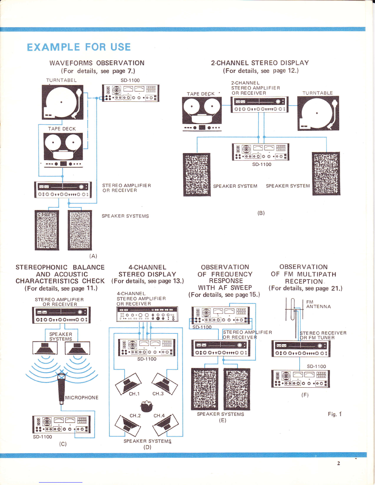
DISPLAY OF 4.CHANNEL STEREO SIGNALS
ln addition to normal 2-channel stereo signals, the oscillo-
scope can be used to show all four signals of a 4-channel
system simultaneously, permitting accurate balance and
phase checks.
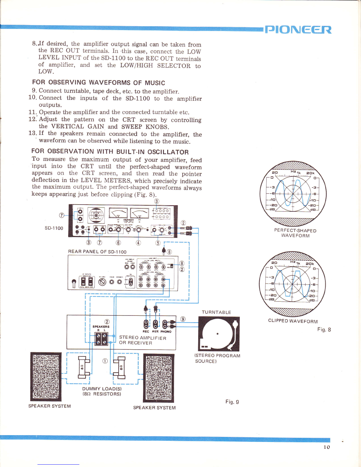
DISTINCT, CLEARLY READABLE OSCILLO-
SCOPE IMAGE
The 75mm (3in.) screen shows a clearly def ined image
even of quickly changing signals, and the practical scale
on the screen makes various adjustments and readings easy.
For extra protection of the screen, a special circuit automa-
tically dims the beam when only a spot is displayed, to
prevent burning of the phosphorescent layer.
EASY.TO READ LEVEL METERS
The large, clearly readable level meters on the front panel
permit easy readout of various level measurements. The
meter range is adjustable in 10dB steps from 20V full
scale (+20d8) to 20mV (-40dB) in accordance with the
various input terminals of different sensitivity.
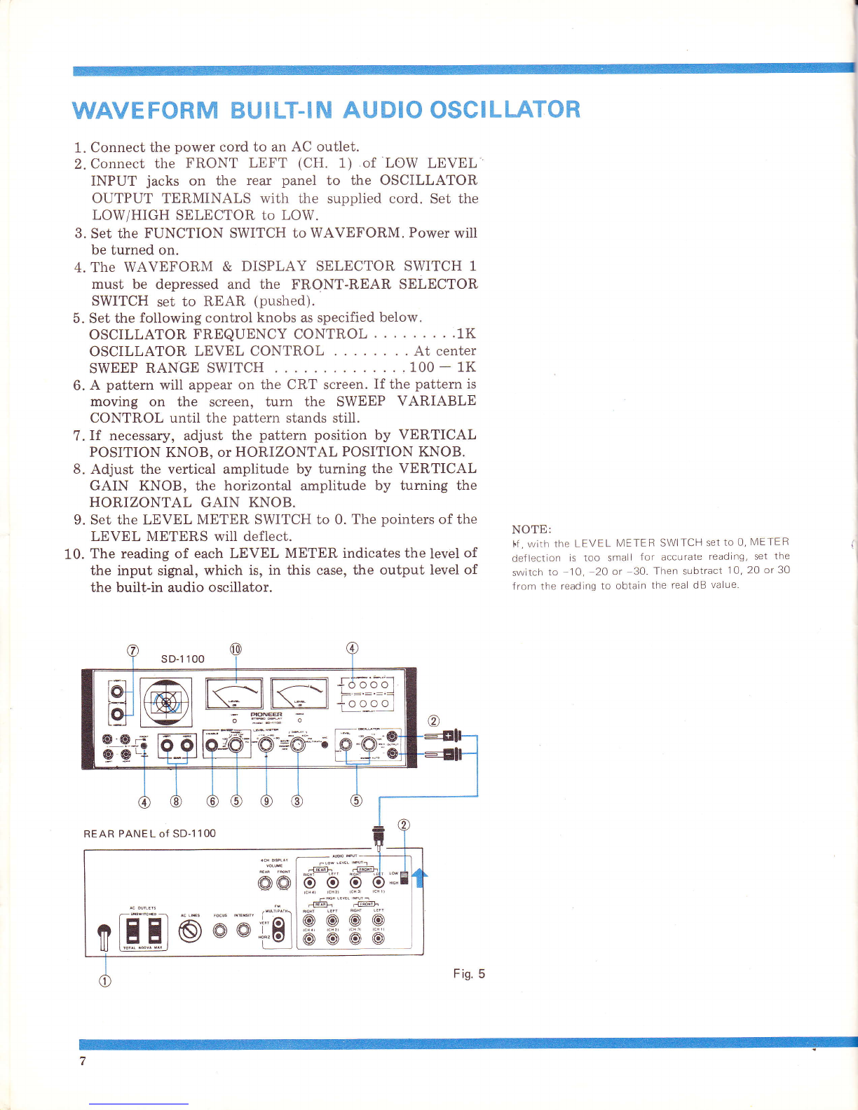
BUILT-IN AUDIO SIGNAL GENERATOR
For frequency response measurements to amplif iers etc., the
SD-1 100 contains an audio signal oscillator with frequencies
freely adjustable from 2OHz Lo 2OkHz. Set at SWEEP
AUTO, the oscillator will automatically sweep over the
whole 20Hz to 20kHz band in a cycle of approximately
25 seconds.
meters, an audio,signal generator with sweep capa-
bility, and a sweep generator.
As this unit is rather more complicated in its
design and operation than other audiocomponents,
please study the following instructions very care-
fully and keep the manual at hand for reference.
AUDIO SWEEP FACILITY FOR DIRECT
OBSERVATION OF FREOUENCY RESPONSE
The frequency characteristics of tone controls, filters,
crossover networks, loudspeakers, etc. can be observed on
the scope, and peaks and dips can be detected. This is
possible by utilizing the audio oscillator sweep for hori-
zontal scope beam deflection.
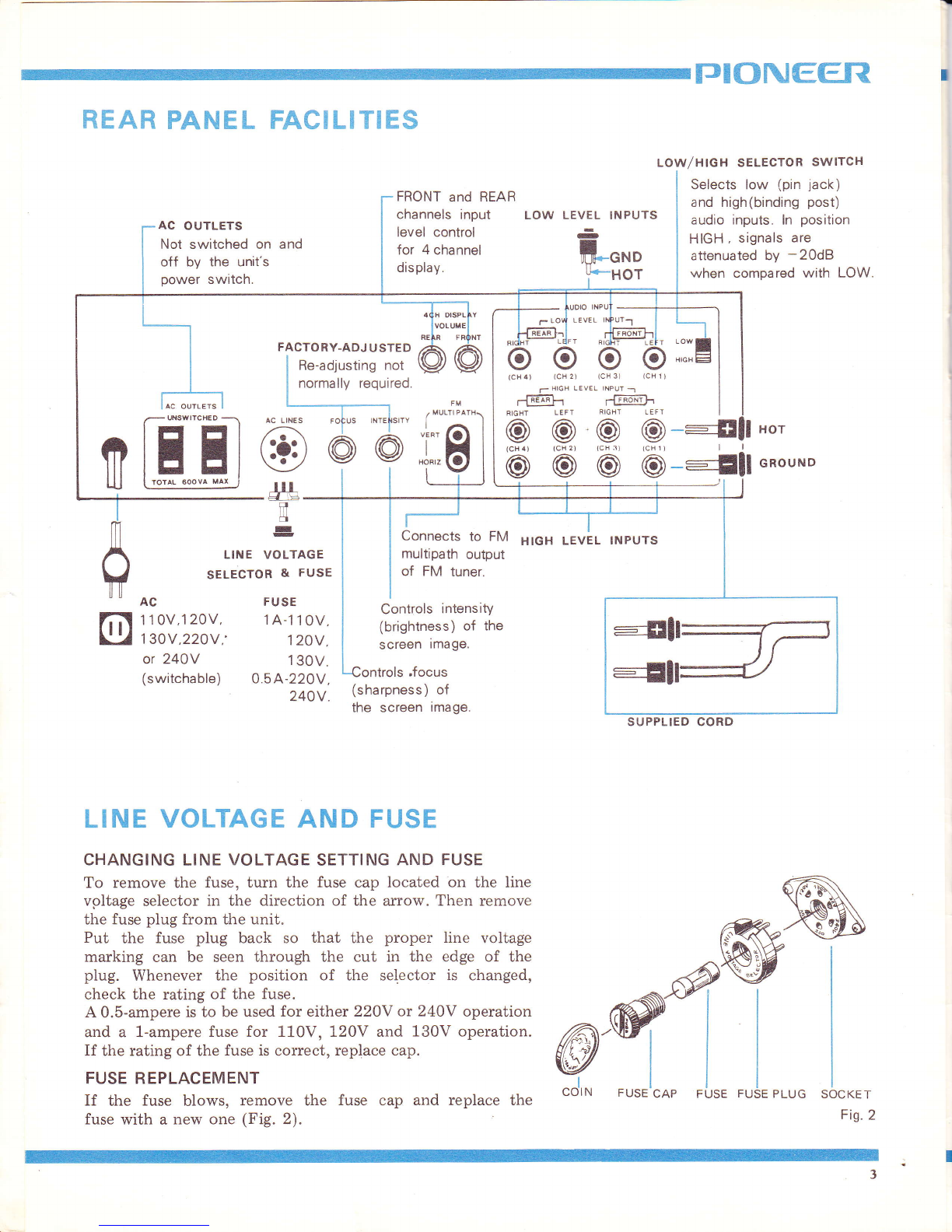
VERSATILE, EASILY SWITCHABLE INPUTS
High level inputs accept comparatively strong signals (as
from amplifier's speaker outputs), while low level inputs
are provided on the front and rear for low level signals
(PRE-AMP out, etc.). lnputs are selected by simple push-
button switches.
MULTIPLE APPLICATIONS
With the built-in signal generator and a good microphone,
the overall frequency characteristics of your stereo system
and listening room can be measured and tone controls etc.
adjusted accordingly for optimum sound. With the Lissajous
display facility, phase relations in a 2-channel or 4-channel
system can be observed and, if necessary, corrected. Accu-
rate balancing is possible with the LEVEL meters. With a
test record or test tape, frequency and other characteristics
of phono cartridges and tape equipment can be checked the
SD 1 100 provides a multitude of uses for scientif ically
accurate system checks.
FM MULTIPATH DETECTION POSSIBLE
FM multipath reception, the greatest enemy of distortion-
free FM sound, can be detected, thanks to the special FM
multipath input provided. (The tuner must be equipped with
a special output.) Thus, the antenna can be precisely
positioned for optimum reception.
o On or near a power amplifier or transformet, and
especially on a vacuum tube type amplifier.
o Moist and dusty places.
o The vicinity of strong magnets, motors, trans-
formers, etc.
WHERE TO PLACE THE SD.llOO
As the SD-1100 is fully equipped with silicon
transistors (except in the cathode-ray tube), it
poses no great problems in regard to heat dissipa-
tion. However, avoid the following kinds of places:
o Direct sunlight and the vicinity of heat sources'

EXAMPLE FOR USE
WAVEFORMS OBSERVATION
(For details, see page 7.)
TURNTABE LsD-1 100
2.CHANNEL STEREO DISPLAY
(For details. ssg page 12.)
2-CHANNE L
STEREO AMPLIFIER
TAPE DECK OR RECEIVER TU R NTAB LE
EETI^E
E-l--fl
@8 @ @r r@ @rrrr@ @ 3
a
(A)
STEREOPHONIC BALANCE
AND ACOUSTIC
CHARACTERISTICS CHECK
(For details, see page 11.)
STEREO AMPLI FIER
OR RECEIVER
4-CHANNEL
STEREO DISPLAY
(For details, see page 13.)
4-CHAN NE L
STEREO AMPLI FIER
OR RECEIVER
.-. O I O...
OBSERVATION
OF FREOUENCY
RESPONSE
WITH AF SWEEP
(For details, see page 15.)
sD-1 100
SPEAKER SYSTEM SPEAKER SYSTEM
(B)
OBSERVATION
OF FM MULTIPATH
RECEPTION
(For details, see page 21.)
@3@@rt@@nr@@3
STEREO AMPLI FIER
OR RECEIVER
SPEAKER SYSTEMS
EET-E
ts-
Ot@ @rr@@nr@ @3
SPE AKER REO RECEIVER
R FM TUNER
@t@@rr@@rn@@3
B@FEffi
B@
3t.@
B@FEffi
RECEI VE
EEII;AE
-
Ot@@rr@@rrrr@OB
SPEAKER SYSTEMS
::oo.OO,l,ooo"
;-....."J. n rlOlr i
SPEAKER SYSTEMS
(F)
Fis. f

lI
t
TJIONEER
REAR PANEL FACILITIES
LOW/HIGH SELECTOR SWlrcH
Selects low (pin jack)
and high(binding post)
audio inputs. ln position
HIGH , signals are
attenuated by -20dB
when compared with LOW.
LEVEL
T
AC OUTLETS
Not switched on and
off by the unit's
power switch.
FRONT and REAR
channels input
level control
for 4 channel
displav.
LOW LEVEL INPUTS
-
ifn*o
Y*HOT
FACTORY-ADJ USTED
Re-adjusting not
normally required
i:Ei
LINE VOLTAGE AND FUSE
CHANGING LINE VOLTAGE SETTING AND FUSE
To remove the fuse, turn the fuse cap located on the line
vpltage selector in the direction of the arrow. Then remove
the fuse plug from the unit.
Put the fuse plug back so that the proper line voltage
marking can be seen through the cut in the edge of the
plug. Whenever the position of the selector is changed,
check the rating of the fuse.
A 0.5-ampere is to be used for either 220Y or 240V operation
and a 1-ampere fuse for 1l-0V, 120V and 130V operation.
If the rating of the fuse is correct, replace cap.
FUSE REPLACEMENT
If the fuse blows, remove the fuse cap and replace the
fuse with a new one (Fig. 2).
n
'i=
WSWITCHED
E@
. dlg_
il
fl
-
@@@@---Efl u*ou*o
HIGH LEVEL INPUTS
LINE VOLTAGE
SELECTOR & FUSE
AC FUSE
1 1 0V,1 20V, 1A-1 1 0V,
1 30V,220V,' 120V,
or 240Y 130V.
(switchable) 0.5A-220V,
240V (sharpness) of
the screen image.
Connects to FM
multipath output
of FM tuner.
Controls intensitY
(brightness) of the
screen image.
@-ffi
FUSE CAP FUSE FUSE PLUG SOCKET
Fis.2
"ol,*


PI()NEEfiI
BEFORE USE, PLEASE OBSERVE:
o INPUT TERMINALS
There are two pairs of inputs on the front panel, four pairs
on the rear panel. The FRONT-REAR switch selects the in-
puts-it has nothing to do with ,,front,' and ,,rear" channels
stereo system (See Fig. 3).
The AUDIO INPUTS on the rear panel are divided into LOW
and HIGH (-20dB). These must be chosen according to the
applied signal level, and switched with the LOW/HIGH
SELECTOR.
o CRT PROTECTOR CIRCUIT
As a constant, singie spot beam could eventually affect the
phosphorescent material on the CRT screen, a special
protector circuit dims the beam whenever the vertical and
horizontal deflections are both smaller than 10mm. Thus, the
beam may dim during a pause in the music when the scope is
used to display a Lissajous pattem.
o THE LEVEL METERS
When meter deflection is too small for accurate reading,
meter sensitivity can be increased by setting the meter switch
at -10, -20 or -30d8. The meters will then indicate 10, 20
30dB more than actual signal level. Be very careful, however,
not to let the meters deflect to the right edge as this might
eventually damage them (See Fig. 4).
. THE OSCILLATOR FREQUENCY CONTROL
When tuming the oscillator frequency control knob very
rapidly in either direction, the signal may sometimes stop
completely. This is no indication of a defect but is due to the
CdS element in the circuit. In such a case, turn the knob to
SWEEP AUTO position once, then turn it slowly to the desir_
ed frequency.
INPUT l and 3terminals
on front panel
,/^' FRONT-REAR
\-) se le croR swtrcH
AUDIO INPUTS
on rear panel
o
I
When switch is off
adjust pointer to 0%
LEVEL METEF|
-10 -Po o
t
When switch is off
adiust pointer to 0%
LOW/H IGH
SE LECTOR
SWITCH
Fis.3
?.?Fr o
ro \rj!l-l: i ra
' "eb --l\<--o
_. .ae
\ LryEL +
dB
no " irifl,,o ,
'60tY..!
o+
LryEL
NW--LUW^
-@- ,t^;ay{ I
I I p p::qI
rt$ilFr rtIqF I
I
@@@@ I
OFF
Fis. 4

WAVE FORM BUI LT-IN AUDIO OSCILLATOR
1. Connect the power cord to an AC outlet.
2. Connect the FRONT LEFT (CH. 1) of LOW LEVEL
INPUT jacks on the rear panel to the OSCILLATOR
OUTPUT TERMINALS with the supplied cord. Set the
LOW/HIGH SELECTOR to LOW.
3. Set the FUNCTION SWITCH to WAVEFORM. Power will
be turned on.
4. The WAVEFORM & DISPLAY SELECTOR SWITCH 1
must be depressed and the FRONT-REAR SELECTOR
SWITCH set to REAR (pushed).
5. Set the following control knobs as specified below.
oScTLLAToRFREQUENCYCONTROL ....1K
OSCILLATOR LEVEL CONTROL . . At center
SWEEP RANGE SWITCH ....100-1K
6. A pattern will appear on the CRT screen. If the pattem is
moving on the screen, tum the SWEEP VARIABLE
CONTROL until the pattern stands stiil.
7. If necessary, adjust the pattern position by VERTICAL
POSITION KNOB, or HORIZONTAL POSITION KNOB.
8. Adjust the vertical amplitude by tuming the VERTICAL
GAIN KNOB, the horizontal amplitude by turning the
HORIZONTAL GAIN KNOB.
9. Set the LEVEL METER SWITCH to 0. The pointers of the
LEVEL METERS will deflect.
10. The reading of each LEVEL METER indicates the level of
the input sigrral, which is, in this case, the output level of
the built-in audio oscillator.
NOTE:
I.f , With thE LEVEL METER SWI TCH SEt TO O, METER
deflection is too small for accurate reading. set the
switch to -1O, 20 or 30- Then subtract 10, 20 or30
from the reading to obtain the real dB value.
REAR PANEL of SD-1 lOO

TJTONEER
CALIBRATION OF WAVE AMPLITUDE
1. Connect the OSCILLATOR OUTPUTS to the FRONT
LEFT (CH. 1) of LOW LEVEL INPUT jacks on the rear
panel with the supplied cord. Set the LOW/HIGH SELEC-
TOR to LOW.
2. Set the FRONT-REAR SELECTOR SWITCH to REAR.
3. Depress the WAVEFORM & DISPLAY SWITCH 1.
4. Set the FUNCTION SWITCH to WAVEFORNI.
5. Set the OSCILLATOR FREQUENCY CONTROL to 1K,
and turn the OSCILLATOR LEVEL CONTROL fully
clockwise.
6. Set the LEVEL METER SWITCH to 0. The LEVEL
(VERT) will indicate to OdB or more.
7. The LEVEL METERS are calibrated in such a way that
OdB corresponds to 2V (rms) when the INPUTS 1 are used
and LEVEL METER SWITCH is set at 0.
8. If amplitude height of waveform is to be calibrated at 1V
(rms), turn the OSCILLATOR LEVEL CONTROL until
the level meter indicates -6d8.
9. The CRT screen will show the waveform of input signal of
1V. Arrest the waveform by controlling the SWEEP
RANGE SWITCH and the SWEEP VARIABLE CONTROL.
10. Adjust the VERTICAL GAIN KNOB to obtain a wave of
the desired height, for instance, between two horizontal
lines on the screen.
NOTES:
1. Do not turn the VERTICAL GAIN KNOB after the
amplitude has been calibrated.
2. To obtain the reference voltaqe of 0.1V, set the
LEVEL METER SWITCH ro -2O, and turn the
OSCILLATOR LEVEL CONTROL unril the pointer
Of thE LEVEL METER iNd|CAIES 6dB.
3. When supplying the signal ro the INPUTS 1 on the
front panei, be sure to set the FRONT-REAR
SELECTOR SWITCH to FRONT.
I
I
I
tg@mgn*H#
Q:
@L
@@
O d d,.El
E
REAR PANEL OF SD.1 1OO
Fis.6
8

CHECK OF OSCILLATING FREOUENCY
If a calibrated audio oscillator is available, the oscillating
frequency of the SD-1100 can be checked by the following
steps.
1. Connect the output of the calibrated audio oscillator to
INPUTS 1 (VERT) of the SD-1100, and connect the OS-
CILLATOR OUTPUTS of the SD-1100 to INPUTS 3
(HORIZ). Set the FRONT-REAR SELECTOR SWITCH to
FRONT.
2. Set the FUNCTION SWITCH to WAVEFORM, and depress
the WAVEFORM & DISPLAY SELECTOR SWITCH 1.
3. Supply a signal of lkHz from the calibrated audio oscilla-
tor to the SD-1100. Its waveform will appear on the CRT
screen. Adjust various control knobs and switches so that
the wave of one cycle will cover the screen.
4. Depress the WAVEFORM & DISPLAY SELECTOR
SWITCH 3 and turn the OSCILLATOR FREQUENCY
CONTROL KNOB until exactly the same waveform will
appear on the CRT screen as in step 3, above. Never use
the SWEEP RANGE SWITCH and the SWEEP VARIABLE
CONTROL KNOB in this case.
5. If the CRT screen shows a wave of one full cycle, the
oscillating frequency of the SD-1100 is 1kHz. Likewise,
a waveform of two cycles or four cycles represents an
oscillating frequency of 2kHz or 4kHz, respectively
(Fig. 7).
6. By varying frequency of the calibrated audio oscillator, the
oscillating frequency of the SD-1100 can be checked at
each point from 20Hz to 20kHz.
WAVEFORM OF AMPLIFIER OUTPUT SIGNAL
1. Connect dummy load(s) to the speaker outputs of the
amplifier.
2. Connect the OSCILLATOR OUTPUTS of the SD-1100 to
AUX input terminals of the amplifier. Likewise, connect
the output terminals of the amplifier to the FRONT LEFT
(CH. 1) of HIGH LEVEL INPUTS of the SD-1100. Set
the HIGH/LOW SELECTOR to HIGH.
3. Check that the WAVEFORM & DISPLAY SELECTOR
SWITCH 1 is depressed, and then set the FRONT-REAR
SELECTOR SWITCH to REAR.
4. Set the FUNCTION SWITCH to WAVEFORM.
5. Apply a test signal from the SD-1100 oscillator to the
amplifier by turning the OSCILLATOR LEVEL CON-
TROL.
6. Adjust the pattern with the SWEEP RANGE SELECTOR
and the SWEEP VARIABLE CONTROL.
?. If necessary, adjust the position and amplitude of the
waveform with the VERTICAL POSITION, HORIZON-
TAL POSITION, VERTICAL GAIN and HORIZONTAL
GAIN KNOBS.
2 cycLES Fig. 7
NOTE:
For this frequency check, a test record or test tape with
signal of predetermined frequency recorded can be
used instead of a calibrated audio oscillator.
NOTES:
1. The pattern can be observed with the speaker
systems connected to the amplifier.
2. An BA resistor having a power capacity twice as
large as the rated output of the amplifier should be
used as the dummy load.
1 CYCLE
2 CYCLES

TJIONEG,R
8.Jf desired, the amplifier output signal can be taken from
the REC OUT terminals. In .this case, connect the LOW
LEVEL INPUT of the SD-1100 to the REC OUT terminals
of amplifier, and set the LOW/HIGH SELECTOR to
LOW.
FOR OBSERVING WAVEFORMS OF MUSIC
9. Connect turntable, tape deck, etc. to the amplifier.
10. Connect the inputs of the SD-1100 to the amplifier
outputs.
11.. Operate the amplifier and the connected turntable etc.
1-2. Adjust the pattern on the CRT screen by controlling
the VERTICAL GAIN and SWEEP KNOBS.
13.If the speakers remain connected to the amplifier, the
' waveform can be observed while listening to the music.
FOR OBSERVATION WITH BUILT.IN OSCILLATOR
To meausre the maximum output of your amplifier, feed
input into the CRT until the perfect-shaped waveform
appears on the CRT screen, and then read the pointer
deflection in the LEVEL METERS, which precisely indicate
the maximum output. The perfect-shaped waveforms always
keeps appearing just before clipping (Fig. S).
sD-1 100
l------'r
REAR PANEL OF SD.l 1OO
PE R FECT-SHAPED
WAVEFORM
I
I
I
I
I
L
I
I
J
r----
I
I
--_--__J
L_:__ i
TURNTABLE
(STEREO PROGRAM
SOU RCE }
Fis.8
r----
I
DUMMY LOAD(S}
(8a RESTSTORS)
' eo Fzlk aor \
o \--j-<--il o '
ffi;
@EE
.;*;-
@@
offilo668 oooo
.@r d@
@@@@
@@@@
REC aUX P|{O{O
STE REO AMPLI FIE R
OR RECEIVER
CLIPPED WAVEFORM
SPEAKER SYSTEM SPEAKER SYSTEM Fig.9

STEREOPHONIC BALANCE AND ACOUSTIC
C HARACTE RISTICS
By connecting a high-quality dynamic microphone for
measurement to the SD-1100, stereophonic channel balance
and acoustic characteristics of the listening room can be
checked (Fig. 10).
1. Connect the OSCILLATOR OUTPUT TERMINALS of
the SD-1100 to the AUX terminals of the amplifier.
2.Place the microphone (impedance: about 50 kO) at an
equal distance from each speaker as shown in Fig. 11.
3. Connect the microphone plug to the MIC jaek of the
SD-1100. Set the FUNCTION SWITCH to WAVEFORM.
4. Set the OSCILLATOR FREQUENCY CONTROL to 1K,
and turn the OSOLLATOR LEVEL CONTROL clockwise.
5. Operate the stereo system, and then, operate the lefL
channel speaker only.
6. Set the SWEEP RANGE SELECTOR to l-00 - 1K, and lock
the pattern on the screen by turning the SWEEP VARI-
ABLE CONTROL.
7. Adjustthe amplitude of the waveform with the VERTI-
CAL GAIN KNOB.
8. Select the LEVEL METER SWITCH to 0, -10, -20 or
30 for easier reading. Then take a reading of the VERT
LEVEL METER.
9. Now, operate the right-channel speaker only. Take LEVEL
meter reading.
.0. If the readings obtained in steps 8 and 9 are much
different, stereo balance is not proper. In most cases, this
condition can be corrected with the amplifier's balance
control.
.l 1. For observing stereo balances over the whole audible
frequency spectrum, set the OSCILLATOR FREQUENCY
CONTROL KNOB to SWEEP AUTO and observe the meter.
l-2. For meaningful measurements of system and room charac-
teristics, the microphone should be placed at the usual
listening place.
NOTES:1. lf the oscillator output is too high, the pattern may be distorted
or the speaker may be damaged.
2. Do not turn the control knobs and switches from their settings
while observing the patterns and reading the level.
SPEAKER SYSTEMS
Y
MICROPHONE
RIGHT CHANNE L
tEr
EOU
i
/
AL DISTANCE ./
/
,
,
r-r l-----l
,qi r#\l
O r\-:zill
L:rt-
;3{ qF ffihPe:::l
sPEAKERS E EJ E
STEREO AMPLIFIER
OR RECEIVER
SPEAKER
SYSTEMS
MICROPHONE
LEFT CHANNEL
ll
Fig. 11

z.CHANNEL STE REO DISPLAY
With the left and right-channel signals fed to the SD-1100,
a Lissajous pattem can be obtained on the CRT screen, which
allows simultaneous observation of the structure of stereo
sounds. It also permits distinction between stereo and mono
signals and shows peak level.
1. Connect turntable, tape deck, etc. to the amplifier.
2. Connect the L and R output terminals of the amplifier to
the FRONT LEFT and FRONT RIGHT of HIGH LEVEL
INPUTS (CH. 1 & 3). Set the LOW/HIGH SELECTOR to
HIGH.
3. Set the FUNCTION SWITCH to DISPLAY 2 CH.
4. Set the FRONT-REAR SELECTOR SWITCH to REAR.
5. Operate the stereo amplifier and the connected audio
equipment.
6. Depress the WAVEFORM & DISPLAY SELECTOR
SWITCH 1 and the DISPLAY SWITCH 1.
7. Play a monophonic program.
Regulate VERTICAL GAIN and HORIZONTAL GAIN so
that the screen will show a straight slanted line as shown
in Fig. 12. This straight line is the standard pattern for a
mono signal.
8. The DISPLAY SWITCH 3, when depressed, allows the
straight patterns to change into circular movement, show-
ing differences between two channels of stereo.
9. The LEVEL METER (VERT) indicates the left-channel
signal; the LEVEL METER (HORIZ) shows the right-
channel signal.
10. If the speakers remain connected to the amplifier, the
stereo display can be observed while listening to the music.
sD-l 1 00
REAR PANEL
oF SD-l 100
AMPLIFIE R
OR RECEIVER
IVIONO SIGNAL
STEREO SIGNAL
{2.CHANNE L STE REO DISPLAY}
rrloNEefit
Fig. 12
TUBNTAB LE
(PROGRAM SOURCE)
ot tat
io $erl
L_Jt-t flel.-=q=- F.0i3
HEI o .;'g
L!*g e
SPEAKER SYSTEMS Fig. 13

4.CHANNEL STEREO DISPLAY
With the SD-1100, it is possible to display a pattern of all
four signals of a 4-channel system simultaneously. With this,
4-channel balance and channel separation can be checked
easily and accurately.
1. Connect the 4 outputs (CH. 1, 3 for front, CH. 2, 4 fot
rear) to the corresponding HIGH LEVEL inputs on the
rear of the SD-1100 (Fig. 16).
When using the amplifiers TAPE REC or preamplifier out-
puts, however, connection must be made to the LOW
LEVEL inputs on the SD-1100. Set the HIGH/LOW
SELECTOR accordingly.
2. Set the FUNCTION SWITCH to DISPLAY 4 CH position.
3. Set the 4CH. DISPLAY VOLUME knobs provided on the
rear panel of the SD-1100 to clockwise extremes. Connect
output (1kHz or lower) of the SD-1100 audio oscillator
to the CH. 1 input of the four-channel amplifier. Set
VERT GAIN and HORIZ GAIN knobs so that the trace
on the CRT screen extends from the origin at 315" (45'
above the X-axis), as shown in (A) of Fig. 15.
4. Connect the audio oscillator output to the CH.2 input'
This time, the trace will extend from the origin at 225"
(45" below the X-axis), as shown in (B) of Fig. 15. Adjust
the 4CH. DISPLAY VOLUME knobs so that the length
of the trace is the same as that of step (3) above.
Note that splatter at the end of the trace in this case indi-
cates distortion, that is, excessive input. Turn the 4CH.
DISPLAY VOLUME knobs to the left (to drop the
input signal level) and the VERT GAIN and HORIZ GAIN
knobs to the right to set the angle. Refer to (C) of Fig. 15.
5. Operate the stereo system, play a 4-channel program.
The screen will show a moving pattern somewhat like a
dancing jellyfish (Fig. 17).
(In 4 CH display, the WAVEFORM & DISPLAY as well
as the DISPLAY buttons have no function except when
LEVEL METERS are used.)
DIRECTIONS OF EACH CHANNEL (CH.1, CH.2,
CH.3, CH.4) IN 4-CH. DISPLAY.
F iE. 14
Fis. 15

2-CHANN E L
STE REO SIGNAL
TJI()NEER
RIGHT
REAR
Fig. 16
4-CHANNE L STE RE O SIGNA L
(4.CHANNEL STE REO DISPLAY)
Fis. i7
REAR PANEL OF SD-1 lOO
4-CHANNE L
STE REO
AMPLI FIE R
:'l T---.--l
Oi l/.r#'\l
i--] llr{#+1Jl
101 l\'"1.-/l
L-li-l
HflTF EM
-N
^ .-/A\-l i)!i-- :*-- *
6@@fg
*-r.rr r& rrl
o o o o*l
ti4 dl@ ^
d L.ir M unlll
SPEAKER SYSTEMS
MONO SIGNAL

OBSERVATION OF FREOUENCY
RESPONSE WITH AF SWEEP
Frequency response of amplifiers, tone controls, filters,
loudness circuits, crossover networks, etc. can be observed
by utilizing the SD-1100's sweep oscillator.
1. Use the output signal from the OSCILLATOR OUTPUTS
as input for the amplifier etc. to be measured (Fig. 19).
2. Connect the amplifier's Iow level outputs (PRE-AMP out,
TAPE REC out) to INPUTS 1 on the front panel. Set the
FRONT-REAR SELECTOR SWITCH to FRONT.
3. Set the FUNCTION SWITCH to WAVEFORM, and
depress the WAVEFORM & DISPLAY SELECTOR
SWITCH 1.
4. Turn the SWEEP RANGE switch to AF SWEEP'
5. Set the OSCILLATOR FREQUENCY control at 2O Hz.
6. Set the amplifier etc. to be measured in operation.
7. Adjust the HORIZONTAL POSITION knob so that a
spot or a vertical line appears on the left-most line (20)
of the screen (Fig. 18).
B. Now turn the OSCILLATOR FREQUENCY control to 20
kHz. Adjust the HORIZONTAL GAIN control so that the
spot or line appears on the right-most line (20k) on the
screen Adjust the height of the line with the VERTICAL
GAIN control (Fie. 18).
9. Now turn the OSCILLATOR FREQUENCY control to
SWEEP AUTO.
10. The oscillator now sweeps across the whole range from 20
Hz to 20kHz in a cycle of about 25 seconds, and the line
travels from left to right across the screen.
Peaks and dips in the frequency response of the test piece
are indicated by lengthening and shortening of the vertical
line, respectively. This gives a fairly good idea of the equip-
ment's frequency characteristics (Fig. 20).
To obtain accurate adjustment, repeat the procedures of
steps TandBafewtimes.
EOUALIZE R CHARACTE RISTICS
TONE CONTROL
CHARACTE RISTICS
HrcH cur FTLTER Fig.20
CHARACTE R ISTICS
*@::-
Fig. '18
oo
PRE OUTPUT
AMPLI FIER NETWORK, FILTER, EtC.
15
F ig. 19

PIONEEFI
MEASUREMENT OF PHASE SHIFT ANGLE
Phase shift of an amplifier can be checked by using the output
and input signals of an amplifier for a Lissajous pattem.
1. Connect a preamplifier or stereo amplifier to the SD-1100
as shown in Fig. 22.
2. Supply the input signal to the INPUTS 3 and adjust for
horizontal pattern as shown in (a) of Fig. 21.
3. Supply the signal to INPUTS 1 and obtain a vertical pattern
in the same manner as in step 2 above.
4. Display a Lissajous pattern on the screen by setting the
following switches as specified below.
WAVEFORM & DISPLAY SELECTOR SWITCH. . . . . . 1
DISPLAY SWITCH . .. 3
FUNCTION SWITCH .. .. DISPLAY 2 CH.
5. The screen will show a Lissajous pattern as in (c) of Fig.21.
6. Phase angle 0 can be obtained as follows:
Sin 0 = B/A
Where A: Length of the horizontal pattern obtained in 2
above
B: Distance between two points at which the
Lissajous pattern crosses the horizontal axis.
(b)
+++$*
Fis.2l
45" 90" I 35" l AO"
(")
sD-1 100
STEREO PREAMPLIFIER
r-t
(@)l
l\ry1
r@g
]ffi] , "..:..91
lL\___l lL\_Jl {;;1.-
;*ff;
ls@l-@=o--i _@"_@:
PRE,OUTPUT REC AUXTPHONO
--r [--E--]
Ol /-.+-\l
r0 [w] Hffi
lo:@=f@-=@-'";
STEREO AMPLIFIER
OR RECEIVER
Fig.22
DUMMY LOAD (8O)
t6

MEASUREMENT OF VOLTAGES AND POWER
MEASUREMENT OF LOW LEVEL SIGNAL
1. Use INPUTS 1 on the front panel, or the LOW LEVEL
INPUTS on the rear panel.
2. If calibration of amplitude has been completed, voltage and
power (including peak screen) can be deduced from the
wave amplitude on the screen.
3. Since the LEVEL METERS provide a direct reading of a
level in dB, voltage and power value can be calculated from
the diagram as shown in Fig. 24. "fhe solid line is to be
used for voltages, the dotted line for power.
4. If the level is OdB, the voltage is obtained as 2V (solid
line); if the level is -6dB, the voltage is 1V; and -10dB
means 0.63V.
MEASUREMENT OF HIGH LEVEL SIGNALS
1-. Voltage up to 2V and power up to 5O0mW (into 8Sl) can
be measured if connection is made to the HIGH INPUTS
on the rear panel.
2. After calibration of amplitude has been completed, voltage
and power (including peak values) can be calculated from
the wave amplitude on the CRT screen.
3. Voltage and power of input signal can be calculated from
diagram below and from the LEVEL METER reading as
in the case of measurement of a low level signal. Multiply
the voltage indicated in the diagram by 10 to obtain high
level voltage.
4. At OdB meter reading, the voltage of the input signal is
20V (10 times 2V).
5. Likewise, if the meter reads 0dB, the power is 50W.
-row L.vEL r*Url
'G4' rrmrh
oooo
-lraFl- r@F'
@@@@
@@@@
^-2
P-a
!
6-s
;- -10
o -12
o-2
t *22
lt -zt
f,t -za
> -28
J -30
lrl -32
i-ll
0.2 0.40.6 I4 6810 203040
ABSCISSA FOR USING SOLID LINE
ABSCISSA FOR USING DOTTED LINE
NOTE:
When levels more than 20V or 50W (8O) are measured.
the measurement should be made with an attenuator as
shown in Fis.23.
V : UNIT
W: UNIT OF
OF
INPUT TERMINALS OF SD-l 1OO
Fis. 23
VOLTAGE
LOW INPUT
r7
l-J
0.0 I 0 .02
Fig.24

TJIONEEfiI
MEASUREMENT OF AMPLIFIER GAIN
Amplifier gain is expressed by the following formula:
VOLTAGE GAIN (Av) = qutput voltage
lnput voltage
or Av (dB) = Output level (dB) - Input levet (dB)
MEASUREMENTS
1. Connect the SD-1100's OSCILLATOR OUTPUTS to the
INPUTS 1 on the front panel and to the amplifier,s AUX
inputs. Connect the amplifier's speaker outputs to the
HIGH LEVEL inputs on the rear panel of the SD-1100,
and set the HIGH/LOW selector switch to HIGH (Fig. 26).
2. Read the signal levels at the time the FRONf-nnan
SELECTOR SWITCH is set to FRONT and at the time the
switch is set to REAR.
3. For instance, if the reading is - 10dB with the FRONT-
REAR SELECTOR SWITCH set to FRONT, and - bdB
with the SWITCH set to REAR, the gain can be obtained
as follows:
Gain (dB) = (-5 dB) - (-10 dB) + * 20 dB = 2b dB
* Fixed attenuation value for rear HIGH LEVEL input.
NOTE:
For measuring gain of a high sensitive amplitier, set
the SWITCH in Fiq. 25 to "b" posirlon and use rhe
following formula:
Gain (dB) = (Level of signal supplied to the H IGH
LEVEL INPUTS of rear panel) _ (Levei
of signal supplied to the INpUTS on the
front panel) + 60d8.
With thE OSCI LLATOR FREOUENCY CONTROL
KNOB set to SWEEP AUTO, and reading the REAR
INPUT LEVE L, you can measuTe gain in the whote
2OHz to 2OkHz ranqe.
oooo
-@- l.@
@@@@
@@@@
REAR PANEL OF SD.1 lOO
AMPLI FIER OR RECEIVER
DUMMY LOADS (8O) F is. 26

CHECKING THE CHARACTERISTICS OF
A PHONO CARTRIDGE
Frequency response, trackability and channel separation of
a cartridge can be checked with the SD-1100. As illustrated in
Fig. 27, connect a tumtable to a standard preamplifier con-
nected to the SD-1100, and play a test record with the car-
tridge to be checked.
Use of test records STR-5001, STR-5002, STR-100, STR-101
of CBS or QR-2009 of B & K is recommended. The pre-
amplifier must be capable of providing equalizing response
calibrated within t 1dB of RIAA standard characteristics for
magnetic cartridges.
CHECKING FREOUENCY RESPONSE
To measure the frequency response of cartridge a test record
with a sweep signal must be played.
1. Play the test record and feed the output of the tumtable
to the input terminals of the preamplifier. Connect the
REC output terminals of the preamplifier to the INPUTS
1 and 3 of the SD-1100. Be sure to connect the left-
channel leads to INPUTS 1; the right-channel leads to
INPUTS 3.
2. Set the FUNCTION SWITCH to WAVEFORM, and the
FRONT-REAR SELECTOR SWITCH to FRONT.
3. For observing the frequency response of the left channel,
depress the WAVEFORM & DISPLAY SELECTOR
SWITCH 1; for observing the frequency response of the
right channel depress the WAVEFORM & DISPLAY
SELECTOR SWITCH 3.
4. Adjust the wave amplitude by controlling the VERTICAL
GAIN and the HORIZONTAL GAIN knobs, and adjust the
SWEEP RANGE SWITCH and the SWEEP VARIABLE
CONTROL so that the pattern stands still on the CRT
screen.
TU RNTABLE
Fl Fl -%_T-e_el
L\sJl lL\rjl '.r o o-9 o
;HH;
STEREO AMPLI FIER OR RECEIVER
t9
Fis.27

5. If the frequency response of the measured cartridge is
flat, the CRT screen will show a pattern as in (A) of Fig.
28; if the frequency response is rising towards the high and
low ends, the pattern on the screen will be like(B);and if
the frequency response drops off at both the high and low
ends, the screen will show a pattern like (C).
CHECKING TRACKABILITY
Provide the same connections as for checking of frequency re-
sponse, and play a trackability test record. If the CRT screen
shows such patterns as in Fig. 29, it indicates that the car-
tridge isn't tracking properly.
CHECKI NG CHANN EL SEPARATION
Provide the same connections as for checking of frequency
response, and play a channel separation test band of the
test record.
1. Set the FUNCTION SWITCH to DISPLAY 2CH, and de-
press the WAVEFORM & DISPLAY SELECTOR SWITCH
1 and the DISPLAY SWITCH 3.
2. With the above settings, the LEVEL METER (VERT) will
indicate the level of the left channel signal; and the LEVEL
METER (HORIZ), the right channel signal level.
3. The difference between the reading on the LEVEL METER
(VERT) and that on the LEVEL METER (HORIZ) is the
channel separation of the tested cartridge.
For instance, if only a left channel signal is present, and
the LEVEL METER (VERT) indicates - 2dB and the
LEVEL METER (HORIZ) indicates - 20dB, the channet
separation of the cartridge at the given frequency is 18dB.
i.e. channel separation (- 2dB) - (- 20dB) = 1SdB.
PIONEER
Fis. zg
Fis. 2g
zo
Table of contents
Other Pioneer Stereo System manuals

Pioneer
Pioneer XC-P410T User manual

Pioneer
Pioneer S-DV88SW User manual

Pioneer
Pioneer XR-A6800 User manual

Pioneer
Pioneer IS-21T User manual

Pioneer
Pioneer X-HM10-K User manual

Pioneer
Pioneer CX-J400 User manual

Pioneer
Pioneer X-SMC55DAB-S User manual

Pioneer
Pioneer X-NM1 User manual

Pioneer
Pioneer MS-Z63 User manual

Pioneer
Pioneer X-MDX717 User manual

Pioneer
Pioneer XC-IS21MD User manual

Pioneer
Pioneer RG-1 User manual

Pioneer
Pioneer DEH-X1790UB User manual

Pioneer
Pioneer Elite SP-EC73 User manual

Pioneer
Pioneer DC-Z85 User manual

Pioneer
Pioneer XR-A790 User manual

Pioneer
Pioneer X-SMC00 User manual

Pioneer
Pioneer PL-990 User manual

Pioneer
Pioneer CT-F10 User manual

Pioneer
Pioneer DEQ-P9 Manual