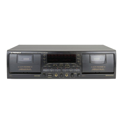
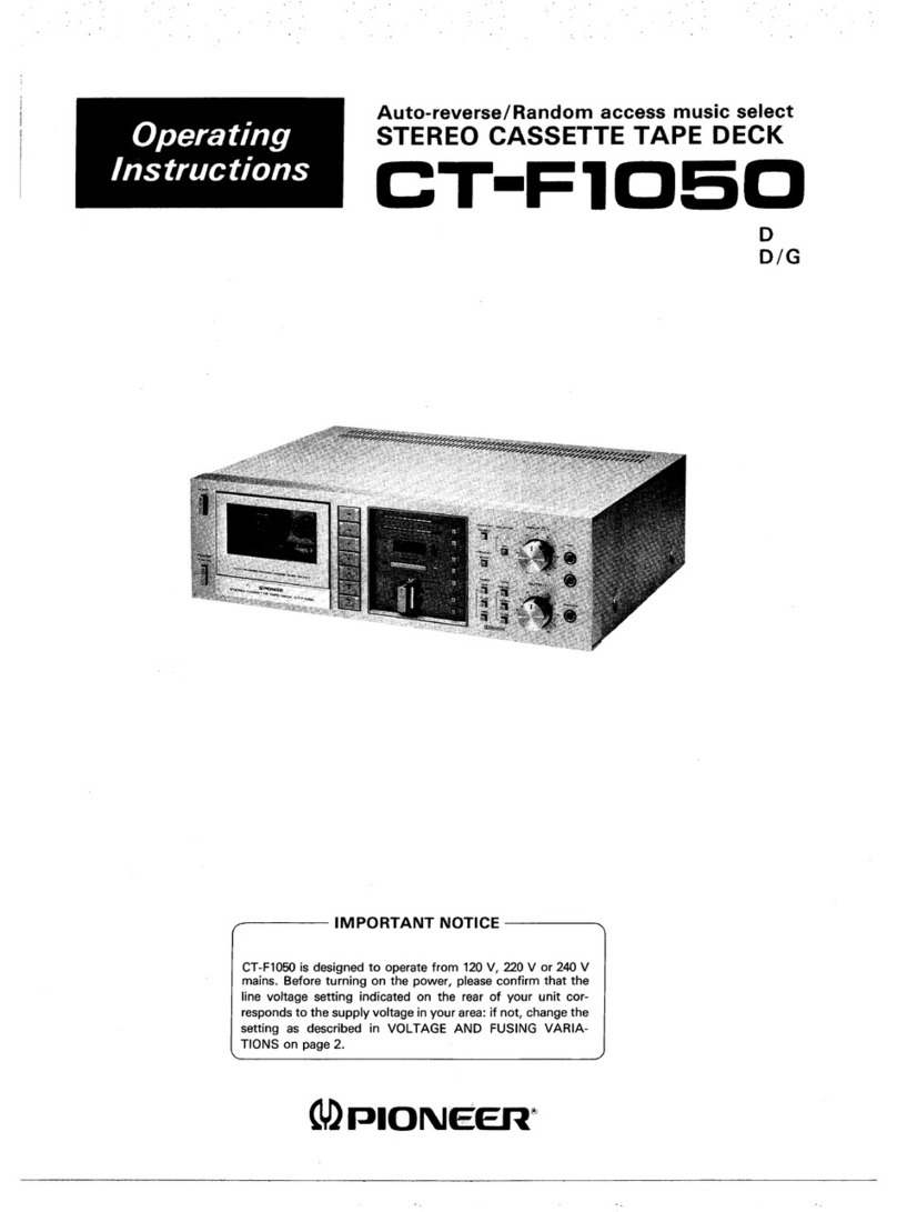
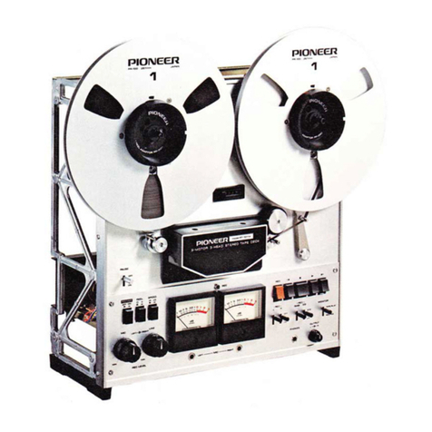
Pioneer WTM-A4 User manual

(!àrqoNeæ
STEREO
CASSETTETAPEDECK
1. SPECIFICATIONS
2. FRONT
PANEL
FACILITIES
3. DISASSEMBLY
4. PARTSLOCATION
5. EXPLODEDVIEWS
AND PARTS
LIST. . . . . .
6. BLOCKDIAGRAM
7. P.C.BOARDS
CONNECTIONDIAGRAM
8. SCHEMATIC
DIAGRAM
9. PACKING
10.ELECTRICALPARTSLIST . . .
1
1. MECHANICAL
ADJUSTMENTS
.
12. ELECTRICAL
ADJUSTMENTS
tr. RÉcr-Rces
uÉcer,ttouES.
.
..
rz.
nÉclnces
ÉlecrnrouEs
..
.
1r.AJUSTESUecÂrurcos
...
...
12.A.JUSTESeIÉcrnrcos
......
2
3
5
7
I
16
19
27
PICINEEFI ELECTFICINIC CCIFIPCIHATICIN 4-1. Mesurc 1-cnohe, Mesurc-ku. Tokyo 1s3, Jap€n
U.A. Prcn|æl E.ECTFtrI\||C3 CCr|PCfùATlCn| €15 Oxfond Dnive. MænæhE. Nlew.JeEey O7O74, USA
P|CNæF E-ECTFEn|IC aA.fEpE N.V, LuiÈhegæffeven 9. æ AnÈre.p, Elelgium
PrcnfæEl B-ETCTFEilICB AIETC|ALIA FTY. LlCt 17B.1æ E}oundany F|oed. BFEæiJe, VbÈcrie 31S. A6E.B|€
YZ @
MAYI98I
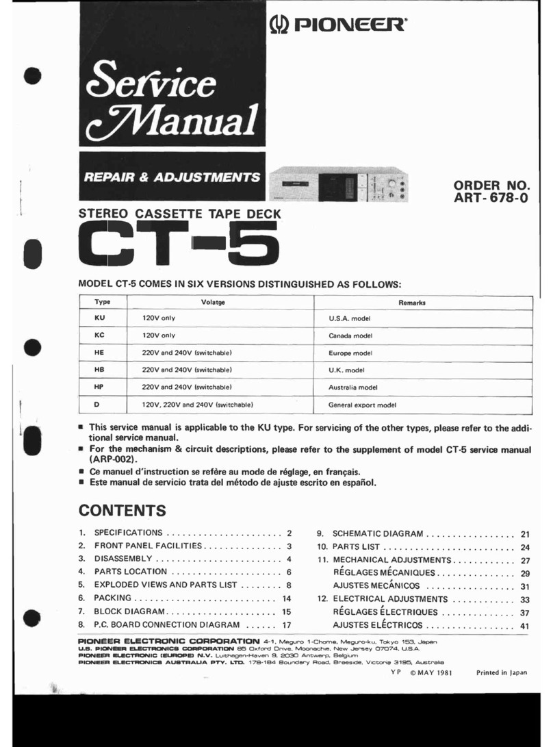
MODEL
CT-6RCOMES
IN SEVENVERSIONS
DISTINGUISHED
AS FOLLOWS:
Thisservicemanualis applicableto ûte KU type. Forservicingof theotrer types,
additionalservice
manual.
o For the circuit & mechanismdescription,
please
refer to the supplement
of
manual
(ARP-001-0).
r Cemanuetd'instruction
se
refère
aumode
deréglaç,en
francais.
o Estemanual
deservicio
tratadelmétododeajusteescritoenespafiol.
CONTENTS
DER
NO.
T-
671
-O
refer to the
-7R sarvice
34
35
40
42
49
51
58
60
12OV,22OV and 24OV (Switchable)
12OV,22OV and 240 (Switchablel U.S.military model
Printed
in ltpan

1. SPEC|FtCAT|ONS
Systems Compactcassette,2-channelstereo
Motor. . . . . DCservo
motorx 1
(Fordrivingthecapstan)
DC
high-torque
motor
x 2 (For
driving
thereel)
Heads
. . . ."Ribbon
Sendust"
recording/playbackhead
x 1
Erasingheadx 1
FastWinding
Time . . . Approximately90seconds
(C-60
tapel
Wow
and
Flutter . . Nomore
than
0.04%
{WRMSI
FrequencyResponse -20dBrecording:
Normal,LHtapes . . . .2O
to 16,000H2
' |.25
to 14,000H2
t3dB)
Chromiumdioxidetape.. .. ..20to18,00OHz
(25
to 16,000H2
t3dB)
(odB
recording;25to 10,000H2)
Metaltape 20to 20,000H2
(25
to 17,500H2
t3dBl
(0dB
recording;25to 15,000H2)
Siganl-to-Noise
Ratio
DolbyNROFF. .... Morethan59dB
DolbyNRON
.. .... BTypemorethan69dB
CTypemorethan79dB
(at
SkHz)
Harmonic
Distortion . . . Nomore
than
1.2%
(OdBl
Input
(Sensitivity/Maximum
allowable
input/lmpedance)
MIC(L,R) 0.3mV/30mVn2k0,6mm diam.
jack
(Reference
MIC
impedance;250O
to 1OkQ)
Lf
NE
(lNPUTl
x2 .. . . . 50mV/25Vl100kQ,
Pin
jack
Output (
Reference
level/Loadimpedance)
LINE
(OUTPUT)x2 . . .450mV/50kO,Pinlack
Headphones . 60mV/8S-t,
6mmdiam.
jack
Subfunctions
a Auto reverse,
autorepeat
functions
o MS/SKIP
(Music
Search/Skip)
system
. RECMUTE
switch
o Dolby NR system
(B type/C type/OFFIwith LED
indicator
lamp
o Stand-by mechanismwith unattended recordingand
playback
o 3 position
Auto tapeselector
(NORM/CrOz
/METAL)
o Full
automaticstopmechanism
o 2color
digital
levelmeter
o 3digitmechanical
tapecounter
o lC-basedlogiccontrol
o Cassettecompartment
illumination
o INDEX
SCAN
system
Miscellaneous
PowerRequirements ..... AC120V/60H2
Power
Consumption 43U\latts
Dimensions . . . .42O
(W)
x 99.5
(H)
x 270
(D)mm
16-9/16
(W)
x 3-15/16
(H)
x 10-5/8
(D)
in.
Weight
(withoutpackage) 5.3kg
(12
lb)
Furnished
Parts
Connectioncordwithpinplugs ....... 2
Operatinginstructions ........1
NOTE:
Specifications and the design subject to poss,ible modifications
without notice due to improvements.
NOTE:
1. Reference
Tapes:
Normal& LH: DIN45513/BLATT
6 orequiv.
CrOz
DIN45513/BLATTT(CrOz)
orequiv.
2. ReferenceRecordingLevel: Meter OdB indicating
level (160nwb/m magneticlevel = Philipscassette
reference
level)
3. Reference
Signal:
333H2
4. Wow & Flutter: o JIS [3kHz,
compensation
(weighted),
rms
valuel
5. Frequency Response:
o Measured
DOLBY NR OFF, level
deviation
indication.
with acoustic
at -20dB level,
is t6dB without
6. Signal
to NoiseRatio: . Measured
at the third har-
monic
distortion
3%level,
weighted.
7. Sensitivity: lnput level(mV) requiredfor reference
recording level with input (REC) controls set to
maximum.
8. MaximumAllowableInput: While
decreasing
settings
of input (REG) level
controls
and increasing
level
at
input
jacks,
thisisthemaximum
inputlevel
(mV)
at
the point where
recording
amplifier
outputwaveform
becomes
clipped.
9. Reference
Output Level:Playback
output level
when
meterindicates
OdB.
1O.This
modeldoesn't
employ
with arecording/playback
connector
(DlN-typel.
I
2.FRONT PANEL FACILITIES
e Powen
switch
The
power
comesonwhenthis
switch
is
depressed;
it is
turned
off
whentheswitch
isreleased.
@ EJECT
switch/cassette
door
The cassette door opens when this switch is depressed.
NOTE.
The door will not open when the tape is running or when the
pausefunction is working.
@ Tape
COUNTER/RESETswitch
The tapecounter
indicates
the tap€'s
traveling
position.
Depressthe reset
switch
before
recordingor playback
to
reset
the
counter
to "000."
@ LEVEL
meters
Theseindicate
the input or output levelduring
recording
or playback.
O Playback
function switches
Playback
operations
canbeperformed
when
thesections
withthe
followingsymbols
are
depressed:
DD (fastforward): The tape runsat highspeed
from
<< (rewindl: left to right.
The tape runs at high speed
from
right
to left.
cif (direction): The direction of the tape travel is
reversed
(even
in the Pause
mode).
@ Recording
function switches
Recordingoperationscanbe perfor
with thefollowing
symbolsare
PAUSE: The tape tra
can be tem
cording
st
switchagainto
the switches
ring recording)
suspended (re-
). Depress
this
recording.
cluring fast
NOTE:
The tape witt not stop when this swirchlis
forward or rewind operations-
REC:
RECMUTE:
seconds),
the tape is automaticall{
Recording
can
This enables blanks
to be
created be ams for con-
venient play (MS/SKIP,
INDEX
SCAN).I
o MS/SKIPswitch ,
This
switch
isfor skippingthe
prof now beingheard
and finding the start of the nex am.When
this
switch
is
depressedduring play (lP indicator
lights)
andthen the fastforward {rewind switch
when traveling
in other direction) il , playstarts
from the next Program.
Whenever is
a longinterval
between tape programs (unr anks of over I
forwarded and
plavback
resumes.
PLAY:
STOP: The tapeisplayed.
The tapeisstopped.

Indicator Assembly Removal
Remove the two hooks (D of the panel stay and
pull the indicator assembly
toward you.
Level Meter Assembly
Remove the hook (J of the panel stay and
pull the level meter assembly
toward you.
Control Switch Assembly
Remove the two hooks (l of the panel stay and
pull the control switch assembly
toward you.
Panel
stay
Controlsuritch
Indicator
assembly oassembly
Level meter assembly
HeadAssembly Removal
1. Remove the stopper.
2. Turn the head assembly clockwise (FWD
direction).
3. Pull up the head assemblyand remove it.
CapstanBelt Removal
1. Remove the four screïi's €) and remove the
capstaneontrol assembly.
2. Remove the capstan belt from the capstan
assembly.
assembly ldler Pulley æsemblY
Fig.3-5 Capstan
beltremoval I
o
Fig.3-4 Headassemblyremoval

I
Forward
running
ind.
Recording
MUTE ind.
Recording
ind.
Reverserunningind.
PAUSEind.
MS/SKIP ind. - ="'o
DO
POWER
ind.
LBY B/Ctype
ind
@ INDEX
SCAN
switch @ ftfUeR start
switch I
This plays
only the start of the recorded
program
for Thisswitch
is
operated
for unattendeO
recordlngjOr
ptay-
about7 seconds
andthen fastforwards
the tape.
When back
using
thetimer.
usedin combination
with the rewind
( << ) switch,
this REC: For automatically
recording
at the Jo,[ r* on
operation
can
beperformed
withthe
tape
being
rewound. the
timer. - I 'T
@ lrupUf lenel
controls OFF: For
when
the
timer
isnotbeing
used. I
These
are used
to adjust
the input signal
level
during PLAY: For automatic
playback
at the timelseil
on the
recording.
The left and right controlsare linked and timer' I I
rotatetogether
but the inside
left channel
anooutsioe @ tvtpx FILTER switch l
right
channel
controls
can
be
used
separately' Depress
this
when
recording
anFM
stereoorolafisr us,ng
@ fUtClacts theDolby
noise
reduction
system. I
lnsert
the microphoneplugs
(L and R) into these
jacks @ OOLSV* NR B/C typeselector i
when
recording
with microphones' Depress
this
to select
type B or typec DolbyiNfr
system
@ pnorugsiack withtheDolby
NRswitch
inthe
oN positiodl.
(ilhe
indi-
lnsert
the
plug
of thestereo
headphones
into
this
jack. cator
BorC lights). I I
@ mooe
setectors @ ooley* NR
oN/oFF
svitch
= : When
thetape
has
been
wound
upon
one
of the Depress
this
to the
ONposition
when
Depress
this
to the
ONposition
when
recordinj
r
back
a
tape
withtheDolby
noise
reduction
sygle
reels' it automatically stops traveling (one-side backa tape
with the Dolby noise
reductionsyj
travel
)
.
.= : The tape starts moving in the forward direction. I
the direction is reversed
at the end of the tape,
the tape starts rnoving in the reversedirection I
andthen stops
at the end (two-side
travel).
and
thenstops
atthe
end
(two-side
travel).
: The
tapeis
repeatedly
played
back. ll
I
* The
word
"Dolby"
and D0 are
trademark
of Dorby
Laboratories
corporation. I
Noise
Reduction
system
manufactured
under
license
fromDorby
Laboratories
Licensrng
corpofatlon

3. DISASSEMBLY
Door Assembly Remova!
1. Depress the EJECT button and open the
cassette
holder.
2. Remove the door assembly from the hooks
attached to cassette holder with the small
screwdriver.
3. Remove the spring with the small screwdriver.
4. Slide the door assemblyto the left and remove
it pulling toward you.
Small screwdriver
Fig.3-1 DoorassemblY
removal
lndicator Panel
BonnetRemoval
Removethefour screws
l)
IndicatorPanelRemoval
1. Push
the two hooks @ of the panel
staywith
the smallscrewdriver.
2. Pull the indicator panel toward you and re-
move
it.
Sub
panel
R Removal
1. Pulloff the INPLIT
knobs.
2. Pustr the four hooks @ of the panel stay
with smallscrewdriver.
3. Pull the sub panelR toward you andremove
it.
$,vitchEscutcheon
Removal
1. Pushthe three hooks (O of the escutcheon.
2. Pull the escutcheon
toward you and remove
it.
Mechanism
AsæmblY
Removal
1. Remove
thecounter
belt.
2. Remove
thesixscrews@
Smallscrewdriver
Sub panel R
o
Y
I
Knobo{lNPUTIFig.
3-2 DisassemblY

Jel
,O,P
fc
I
o.t"
// 96
C
,a
)". -
"r6
. tc
I
E
I
oV
-) tç
r'c
I

cf
8l
oç ^1g1l3ssv lllslNvHc3lll t'9
rsll sluvd oNVS,\^fIA
olooldxf '9
\.t -ll,

4. PARTS LOCATION
Front
Panel
View
KnobC (F
F, REW)
RAC.2O9
Knob {EJECT)
Switchescutcheon
RN
L-338
** Door panel
assembly
RX8.601
Knob (POWER)
BAC-195
Indicâtor
panel
RNL-358
FrontView with Front Panel
Removed
Levelmeter assembly
RAW-161
** Counter
RAW-168
Cassette
plate assembly
RXX-338
Erase
head
RPB-O94
** Head assembty (REC/PB)
RXX.333
NO?ES
o Parts tt'illtoul par
I rtttrrtbct
cartttol bc sttltltltcd
c The r marh found on some component parts indicates the inoportance of the
safety foctor of the par!. Therefore, when replacing, be sure to uâe prts of identico!
designotion
c For your Parts Stoch Control, the fast mot,ing items are indicotedt u'ith the marhs
** and *
** GENERALLY MOVES FASTER ÎHAN *
This classification shall be adjusted by each distributor because lt dtpends on mod.el
number , temperature, humidity, etc
KnobD (REC)
RAC-193
Knob E
RAC- 1
94
Knob
(INPUT
R)
RAA-361
RAA-362
Knob
(MODE
TIMER)
RAA-359
Subpanel
R
R
NL-380
Knob E
RAC.192
l(rto$ D (PLAY, STOP)
RAC!210
KnCùS (DIRECTTON)
RAG.211
Fuctionswi
tch assemblv
RW9il40
Vatiabfo
resistor
(
|NPUT)
RCV-m6
fr Jack
assembty
RKN-075
|lt Rotary
switch
(B)
(MODE,
TIMER)
RSB-03O
** Push
switch (B)
RSG-126
Indicator
æsembly
RAIW-163
LI
.g
I
Knob
(INPUT
Dummy head

TopViewwith Bonnet
Removed
Remote control æsembly
f' ** Fuse
(2Al
4 REK-055
A ** Fuse
(t.
REK-059
A * Porwer
trarsformer
(120V1
RTT.239
Reelmotor control
assembly
B
RWX491
Capstanmotor control
assemblyB
BWX-488
Panel stay
RNT-OI7
Mechanismassembly'
RearPanel
View
Remote control socket
RKP-222
Main chassis
Terminal
RKB-o18
Mother assembly
RWX.5O3
DOLBYNRassembly
1;1
RWX.499
DOLBYNRassembly
1p1
RWX.499
Amplif ier assembly
RWF-G)5
Jackæsembly
RWX-498
Switch assembly
RWS-139
Meter drive assembly
RWX-500
Strain relief
REC-376 I
I

2
NOTT
. PTi-
.Th
sol
det
cFo
t*
*t
Th
nu
XTERIOR
o
Parts
Mark
7t/
69
{
-4--\
./ .-.-)
70
7oF
20
Jr.
lz
o
I
r0
tl
r3
2
+>
li
'l
2
\
\@
o

9d
ry
56
65
/
.,,.
a"

Mark No. Part No. Description Mrk
81. R8H-855
82 RNH-O64
83 RXX-334
84. RNH-061
85. RXB-55?
86. RNL-257
87 RWX-491
88.
89.
90 RWX{88
91.
92 RXX-335
93. R
NL.247
94. RBH-862
95. RNL-268
96 RBH-852
97. RNL-264
98.
99.
100. wAo17D034DO25
Spring
F
G plare
FG coil assembly
FG shieldplate
Bearing
housing
assembly
Trigger leverR
Reelmotor control assembly
B
Heat
sinkA
P.C.B
Capstan
motor control
assembly
B
Cord clamper
Capstan
molor coil æsembly
Thrust receptacle
Pinch
return
spring
R
Subpincharm R
Pinchpressure
spring
R
Ejectlever
Side frame R2 assembly
Heat
sink B
Washer
No. Part
No.
101 YE3OFUC
102. Y52SFBT
103. ATZ26P080FMC
104. VCZ30PO60FMC
105. BMZ30P060FMC
106. VCZ26P100FMC
107 YE25FUC
108. vcz26Pl40FMc
109. ATZ30P080FMC
110 YE2OFUC
111 WA21DO40DO25
't12 PMA26PO50FMC
113. 8MZ26PO50FMC
114. BMZ26P080FMC
115. BBZ26P080FNi
116. VCZ3oP100FMC
117. RNH-1
17
I
Wæher
Washer
Screw
Screw
Screw
Screw
Washer
Screw
Screw
Wæher
Washer
Screw
Screw
Screw
Screw
Screw
Shield
plare
B

o. Parts
uithout part number cannot besupplied
o The [\ marh found on some component parts indicates the importance of the
safety factor of the part. Therefore, when replacing, be surg to use
parts of identical
designation.
o For your Parts
Stoch Controt, the fast moving items are indicated uith the marhs
** and *.
*T GENERALLY MOVES FAS?EF THAN *.
This classification shall
be adjustedby eachdrstributor becauseit depends on model
number , temperature, humidity, etc.
ParGList
Mark No. Part No. Mark No. Part No. Description
Dæcription
1.
2.
3.
4.
5.
11.
12.
13.
14.
15.
16.
17.
18.
19.
20.
21.
22.
23.
24.
r* 25.
RNL.266
RBH.849
RNL-265
RBH-85O
RNL-261
REB-447
RNL.269
RBt{€51
RXB.55O
RNL.267
RBH€61
RNL.253
RNL.254
RNL.255
RNL.3O6
RNL.3O5
FNHO77
BXX-336
RX8-548
BNL.313
RBK.l67
RNL.314
BBA.O73
RPB.Og4
RBH.863
RBH.864
41.
42.
ff 43.
44-
45.
46.
47.
8.
49.
50.
* 56.
57'
58.
59.
60.
61'
A* 62.
63.
64'
65'
REF-022
RNG.306
RXX.333
RNL-317
RNH-076
RBH€60
RBK-169
RNc-267
RNL.272
RNL-271
RBK.170
RNL.273
REB.4æ
RNL-258
RBH848
RNL.259
RBK.164
RBH€46
RXP.I
11
RNL.256
RBF-058
RNL.3O8
RNL.3O7
RXB.57O
RBH-847
REF.O23
REB.26O
RLB.434
RBF-O3O
RBH-857
RBH.858
Rx8-552
RXB-551
REB.467
RBF.O59
36. RNL-262
37. RBA-o74
38. RBH-853
33. RBH-844
40. RXB-556
Lock arm
Lerærspring
Eiect prevent lever
Spring
Cylinder
O ring
Piston
Connector P.C.B.
Cord clamPer
Side frame L2 assemblY
Pinch pressure spring L
Pinch roller arm æsemblY
Sub pinch arm L
Pinch return sPring L
Cam follorrr lever
Hook L
Hook B
Connection Plate
Pinch plate
Actuater
Changp plate
Reel motor drive assembly B
Reelmotor coil asæmblY
Reelmotor P.C.B.
Rotor æsembly
Pocket L
Pressure
sPring
Pocket R
Holder B
Specialnut
Eræe head
Height adiust spring L
Dummy head
Height adiust spring R
Erasehead base æsemblY
Stopper
Azimuth screw
Azimuth spring
GearsPring
Selector gParassembly
Steelball (3ôl
Housing
Headassembly
Head base æsembly
Slide plate
Headbæe spring
Mein shaft
Arm spring R
Arm assembly
Switch leverspring A
Switch lever
REC detector arm
Detector arm
Switch lever spring B
METAL detector arm
Brakeshoe
Brakeplate L
Brakespring
Brake plate R
Halfset
spring
Spring L
Plungersolenoid
Trigçr lever L
Washer
Assist gpar R
Assistçar L
Pulley shaft
ldler pulley 6sembly
Spring R
Chassis
assemblY
Steelball (40!
StopPer
Guideroller
Oil stop washer
Ratch spring L
Ratch spring R
Sub capstan æsembly
Capstan
æsembly
Capstan
belt
Washer
6.
7.
8.
9.
t0. 5r.
52.
53.
54.
55.
26.
27.
24.
29.
30.
* 31.
32.
33,
34.
35,
66.
67.
68.
69.
70.
71.
72.
73.
74.
75.
76.
77.
78.
** 79.
80.

r7l 8
o
REMOTE
CONTROL
Ass'y
I
7
PLi 8V 50mA
CASSETTEHALF
LAMP
Q30r, ,320
25Â933Ltl
q 25Â1O15
or
zSAtt??Nc
n 2S!937
or
x
rcrotS
e3
r,3rl,3r6
2S0860
or
250313
o.
I

Y Asiy(L)
RWX-499
Q601 IC602
VRæ1 VR@ VR6O4

1
BOARDS éorrrruEcrtoN
DIAGRAM
A
REC/P8
HTAD
R
CH t CH
JACK Ass'YFIWX
-498
swtTcH
Ass'y
CONNECTOR
ass'Y
AMP Ass'Y
RWF-o95
5
c
D
2

4
MOTFIER
Ass'y
Q3O6 Q3O7 Qæ2 tCS6
Ic3a2 lcæa Q3o3 IctoT
RWX
-503
orca a309 as1
IC30I Q304 Q30a Q320
lcg Ic93 q1?4 I
Q3æ O33r Q319
Q527 Q5r
6
o323 lC30
rRæz L306 VR301VR305
: lri:ii: î:ll1'lli"'1ljiliï"--;*.,"A1
l.**l*,
--- f :lT-1 *
t\tt
j'' : | -ù;:il|
c!frz.? , I ,,.c I
.1,*tl-
) l at/t6 |
-/' I J
, I 1Â ,?-{
1- ' I o,.--
L@6J1 | At
;"'T.^'*"i'; : I --ïqa
| :l oFF -9. sE
Àll'" : i
r-
l- l- . çil ,' ----*a l,/ . -;'
[16.=,!=,,,*,*{:t I I aGDÀ1
a-:- o3o7-l!t, I
.:1 iT illtll ll: T rc:or-razarse2urDT_4ts,2za,
; 3tïr*r'.'.t:.'.'l'" ll
1P^. IlF" IÊ^",t:1 é tl I .t , sN74Lsr22af
oM74
3E*
TEe
rr"::,il*1 )1.fiA74L5122ot
ÈD74tst22at i OSZgr:t.g::,::S I l
, SN74LS]22
af
oM74Lsr22 , ---::::::-- :,;,^^^
:IC
306
]
J"l
or lllb
c JLior jl*.. ' ô :
I i.io. -- -- '
I ort -9. qti ô 'r - i r c\r17 rc4o658o or
ior r*" roorevrnJ I -" ? -1 ' HD14O66B-
I(s.
t_
4

Parts
List
Daæription Mark No. P.rt No.
M.d( No. Itrt No.
t. RNA-563
2. RXB-595
3.
4.
5. RBH€92
RNL.338
RAC-l95
RNL.358
RAC-209
RAC-21
1
11. RAC-210
12. RBH-902
'r3. RAA-362
14. RAA-3ô1
15.
Bonn€t
Door
panol
ass€mblY
Ooorpan€l
Door
lans
Door
spring
Switchæcutchoon
Knob
(POWERI
Indicator
panel
Knob
C(FF,
REW)
Knob
S(DIRECTIONI
Knob
D (PLAY.
STOP)
Spring
Knob
(INPUT
Ll
Knob
(INPUT
Rl
Moôanism
8s$mblY
Cæsôtto
platoassembly
Lamp
P.C.B.
Bracket
Panelitay
Eject
spring
Knob
(EJECT)
Countor
bolt
Spark
killer
Po$prswitch
Counter
Display
æsombly
B
lsvol rnoter
Ës€mbly
Knob
(MODE,
TIMER)
Function
switch
assemblY
Functionsvrritch
Pushwvitch
Knob
E
Knob
D (RECI
Knob
E
Sub
panelR
i/bther assomblY
Hoat
tink
Terminal
(LINE)
Pushswitch
(Bl
Fuse
(1.2A)
Fuse
(2Al
DOLBY NRasornbly
Connector
socket
assembly
C
Amplif
ier
assambly
P.C.B
holder
Moter
drivt assmbly
Sritch assembly
i:Y
T:
RSB-030
RWX.498
RKN475
RTT-239
REC-355
RDGO22
{RDG-030)
REC-376
RKP-222
REC-369
vBz30P060FMC
vBz30PO80FMC
PBZ26POSOFNi
PMZS)PO6OFMC
FBT4OPO6OFMC
PMZ3OPO6OFZK
vBz3nP060FZK
VBZ4OPl2OFMC
REC-378
80. REC-380
51.
52.
tt 53.
54.
55.
6.
7.
8.
9.
10.
A*
,1\
56.
57.
58.
59.
60.
61.
62
63.
u.
65.
6ô.
6?.
68.
69.
70.
71.
72.
73.
74.
75.
76.
77.
78.
78.
aslombly
l2Pl
16.
** 17.
18.
19.
20'
21.
ff 22.
A 23.
A**
ff
*
t
**
t*
i*
Â**
[**
RXX-338
REL.O91
RNT.OI7
RBH-gO1
RAc-208
RE9-456
RwX-109
(RWX-2341
RSA-O/t6
RAW-168
RAW-I63
BAW-161
RAA-359
RWS-140
'RSG{63
RSG-088
RAC-194
RAC-193
RAC-l92
RNL-380
RWX€O3
RKBOl8
RSG-126
REKO59
REK-055
RWX499
RKP-273
RWFO95
RNL-375
RWX€00
24.
25.
26.
27.
29.
xt.
30.
3l.
32.
gr.
g.
35.
36.
37.
38.
39.
rto.
41.
42.
/l3.
4
/t5.
tl6.
47.
48.
49.
50.
15

6. BLOGK
DIAGRAM a
I
lssol
4P
_f
,,c
VRAOI
rltR l
FLAT AA'P I ,".o.,,,"
llTlr
F.oce -l
,vW
PB EOAMP
-
I
I ogtt
I r-coc-€
CONT
MOC
I
ï
5;
FWO
ë
__._c
Table of contents
Other Pioneer Tape Deck manuals

Pioneer
Pioneer CT-5151 User manual

Pioneer
Pioneer CT-1080R User manual

Pioneer
Pioneer CT-770 User manual

Pioneer
Pioneer CT-F9191 User manual

Pioneer
Pioneer CT-F900 User manual

Pioneer
Pioneer CT-F1000 User manual

Pioneer
Pioneer XC-IS21T User manual

Pioneer
Pioneer CT-730 User manual

Pioneer
Pioneer CT1270WR User manual

Pioneer
Pioneer CT-F9191 User manual

Pioneer
Pioneer CT-3 User manual

Pioneer
Pioneer T-6600 Operating and safety instructions

Pioneer
Pioneer CT-980W User manual

Pioneer
Pioneer CT-1060W User manual

Pioneer
Pioneer CT-3131 User manual

Pioneer
Pioneer CT-70R User manual

Pioneer
Pioneer RT-1020L User manual

Pioneer
Pioneer CT-5 User manual

Pioneer
Pioneer CT1270WR User manual

Pioneer
Pioneer CT-520 User manual