7. The bias oscillator is made by push-pull
circuit of transistors Q7 and Q8. The bias
oscillator output current is fed to the erase
head (E.H.) to erase the signal recorded on
the tape. At the same time, it is supplied to
the recording head (R.P.H.) through the
switch (S t -s ) for recording bias.
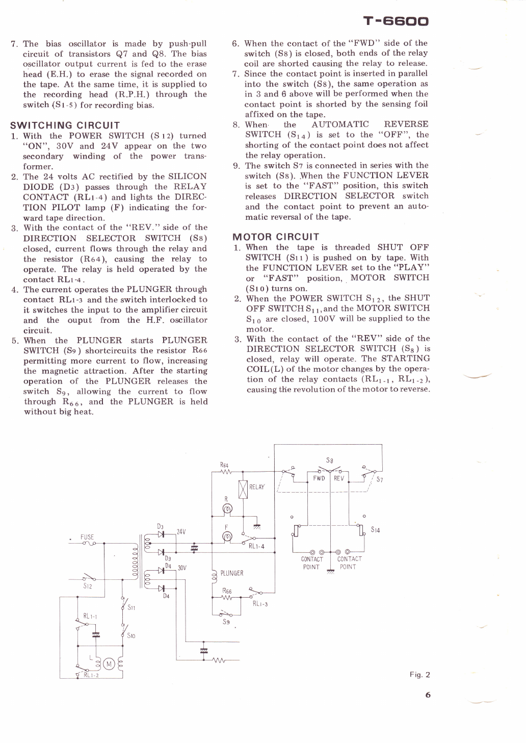
SWITCHING CIRCUIT
1. With the POWER SWITCH (S t z) turned
"ON", 30V and 24Y appear on the two
secondary winding of the power trans-
former.
2. The 24 volts AC rectified by the SILICON
DIODE (Dl ) passes through the RELAY
CONTACT (RLt-+) and lights the DIREC-
TION PILOT lamp (F) indicating the for-
ward tape direction.
3. With the contact of the "REV." side of the
DIRECTION SELECTOR SWITCH (Sa)
closed, current flows through the relay and
the resistor (Ro+ ), causing the relay to
operate. The relay is held operated by the
contact RLt-+.
4. The current operates the PLUNGER through
contact RLr-s and the switch interlocked to
it switches the input to the amplifier circuit
and the ouput from the H.F. oscillator
circuit.
5. When the PLUNGER starts PLUNGER
SWITCH (Se ) shortcircuits the resistor Roo
permitting more current to flow, increasing
the magnetic attraction. After the starting
operation of the PLUNGER releases the
switch Ss, allowing the current to flow
through R6 6 , and the PLUNGER is held
without big heat.
T-EiCioo
6. When the contact of the "FWD" side of the
switch (Ss) is closed, both ends of the relay
coil are shorted causing the relay to release.
7. Since the contact point is inserted in parallel
into the switch (Sa), the same operation as
in 3 and 6 above will be performed when the
contact point is shorted by the sensing foil
affixed on the tape.
8. When the AUTOMATIC REVERSE
SWITCH (Sr + ) is set to the "OFF", the
shorting of the contact point does not affect
the relay operation.
9. The switch St is connected in series with the
switch (Sa). .When the FUNCTION LEVER
is set to the "FAST" position, this switch
releases DIRECTION SELECTOR switch
and the contact point to prevent an auto-
matic reversal of the tape.
MOTOR CIRCUIT
1. When the tape is threaded SHUT OFF
SWITCH (St t ) is pushed on by tape. With
the FUNCTION LEVER set to the "PLAY"
or "FAST" position, MOTOR SWITCH
(St o) turns on.
2. When the POWER SWITCH S12, the SHUT
OFF SWITCH Sr 1,&nd the MOTOR SWITCH
516 are closed, 100V will be supplied to the
motor.
3. With the contact of the "REV" side of the
DIRECTION SELECTOR SWITCH (Ss ) is
closed, relay will operate. The STARTING
COIL(L) of the motor changes by the opera-
tion of the relay contacts (RLr-r, RLr-z),
causing the revolution of the motor to reverse.
Fig.2
6
CONTACT
POINT