Pira P275E User manual

P275E
FM Monitor
User Guide
http://www.pira.cz

2
Contents
1Introduction........................................................................................................................................................................................................ 3
1.1 Using this guide.............................................................................................................................................................................................. 3
1.2 Description of the equipment ......................................................................................................................................................................... 3
1.3 Other documents............................................................................................................................................................................................ 3
1.4 Technical parameters..................................................................................................................................................................................... 3
2Hardware description........................................................................................................................................................................................ 4
2.1 Internal layout................................................................................................................................................................................................. 4
2.1.1 Installation of the P275 board............................................................................................................................................................... 4
2.1.2 Mainboard description .......................................................................................................................................................................... 4
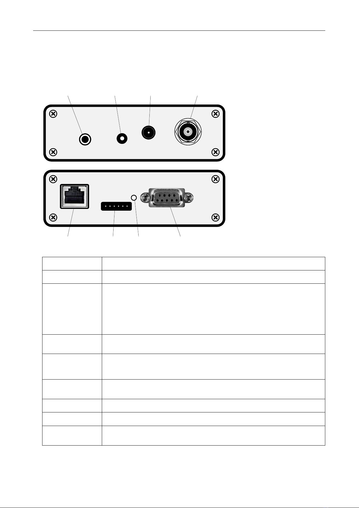
2.2 Connectors, control elements and status indicators ...................................................................................................................................... 5
3Installation.......................................................................................................................................................................................................... 6
3.1 Hardware installation...................................................................................................................................................................................... 6
3.2 Software installation ....................................................................................................................................................................................... 6
3.2.1 Determining the IP address and setting the network parameters ........................................................................................................ 6
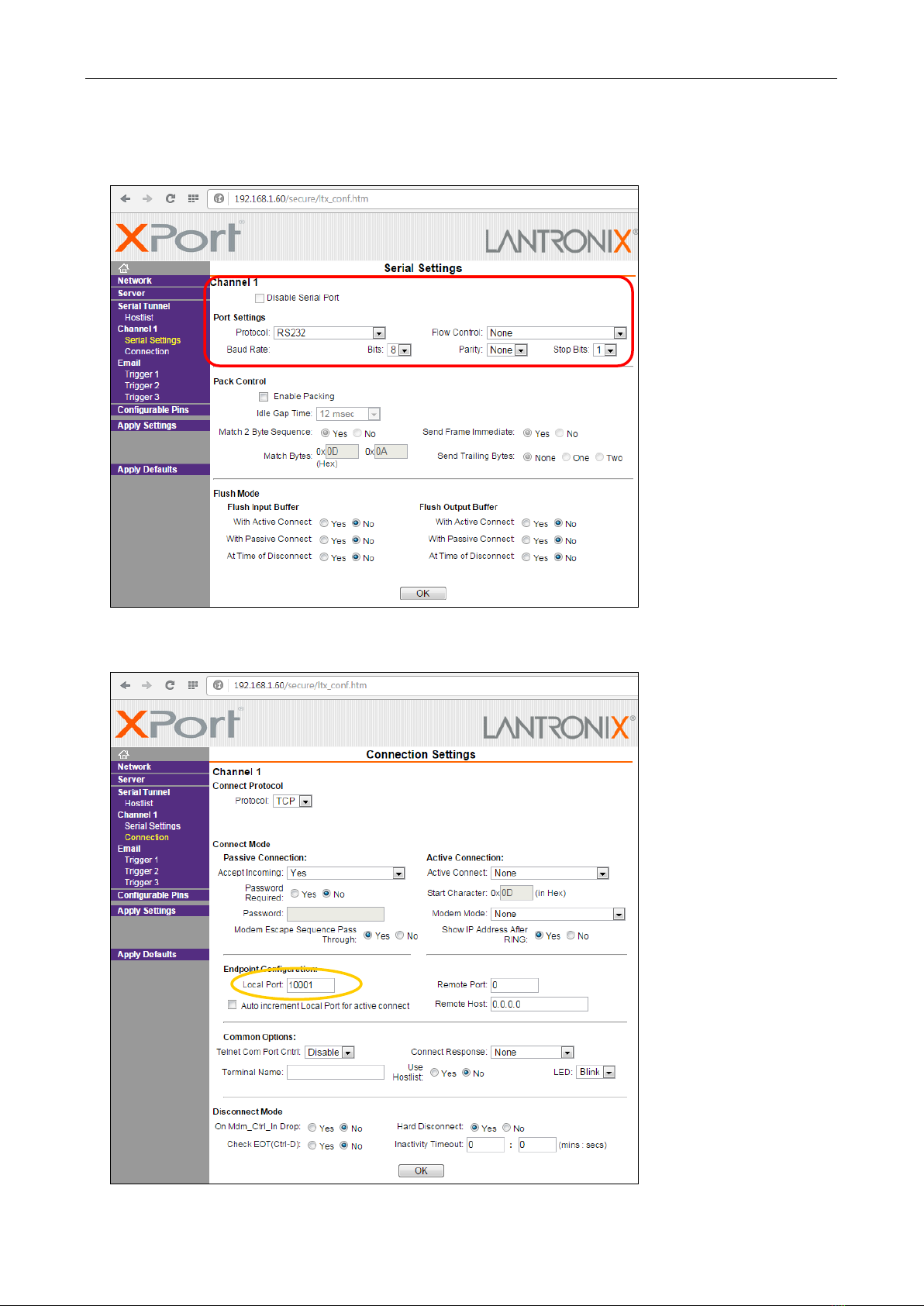
3.2.2 Setting-up the communication parameters........................................................................................................................................... 7
3.2.3 First communication with the FM Scope application ............................................................................................................................ 8
3.2.4 Remote control of the attenuator.......................................................................................................................................................... 8
3.2.5 ALARM outputs .................................................................................................................................................................................... 9
3.2.6 Emergency mode ................................................................................................................................................................................. 9
4ANNEXES.......................................................................................................................................................................................................... 10
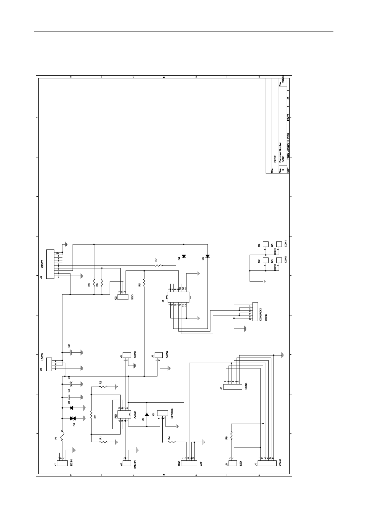
4.1 Connection diagram ..................................................................................................................................................................................... 10
4.2 Part list ......................................................................................................................................................................................................... 11

3
1Introduction
1.1 Using this guide
This guide covers the P275E FM Monitor device. It provides the information needed to install and using the equipment.
Please read this entire guide and familiarize yourself with the controls before attempting to use this device.
If you have any questions or comments regarding this document, please contact us via email.
We welcome your feedback.
1.2 Description of the equipment
The P275E FM Monitor is a quick solution for remote FM modulation monitoring and measurements. The device extends the original P275's
capabilities with direct Ethernet communication and adds some other useful features. The aluminium case provides excellent shielding in
strong RF signal environment. Optional attenuator extends the input power range up to 1W. The device has full support of the FM Scope and
RDS Spy software for Windows.
1.3 Other documents
This document is not a complete reference manual. Please visit the website for more information:
Specification of the Ethernet module Lantronix XPORT-05R (XP1001000-05R), http://www.lantronix.com
P275 FM Broadcast Analyzer User Manual
Support section at http://www.pira.cz
1.4 Technical parameters
Parameter
Value
Outer dimensions
144 x 105 x 37 mm
Power supply voltage
5 V DC
Ripple allowed
max. 100 mV pp
Supply current
max. 350 mA
Power supply connector
2.1 mm
RF input
BNC 50 ohms
Max. input RF power
1 W (attenuator ON) / 10 mW (attenuator OFF)
Attenuator
20 dB (+/- 2 dB)
Unwanted inherent reception
< 35 dBμV
IMPORTANT!!! The device power supply voltage is 5 V. Exceeding that voltage will
result in permanent damage to the device! Always check the power supply voltage
or use original power supply adapter.

4
2Hardware description
2.1 Internal layout
2.1.1 Installation of the P275 board (applies to kit version only)
In the case the P275 receiver board has not been installed yet, follow these steps:
1. Loosen the four screws at the corners of the panel on the side of the BNC connector and eject the panel including the mainboard
2. Place the receiver board in the prepared position on the mainboard, making sure all connectors are properly connected
3. Fix the receiver board with four M2.5 screws on the spacers
4. Insert the assembly back into the aluminium box and screw the panel
The P275 receiver board must contain firmware version 2.2 or later.
2.1.2 Mainboard description
The connection diagram is attached to this document.

5
2.2 Connectors, control elements and status indicators
All the elements can be found on the side panels.
HEADPHONES ATT 5V DC INPUT
ETHERNET ALARM OUTPUTS SIG RS-232
Connector or element
Description
Headphones
Stereo 3.5mm JACK connector for optional connection of headphones.
ATT (RF attenuator)
Controls switchable attenuator for the input signal. The attenuation value depends on specific hardware
configuration, by default it is 20 dB (+/- 2 dB).
The switch has 3 positions:
ON –the attenuator is enabled
OFF –the attenuator is disabled
SW –the attenuator can be remotely controlled, see section 3.2.
For the MPX input signal, the switch must be in OFF position.
5V DC
Power supply connector. Recommended power supply adapter: 5 V, min. 1 A, connector 2.1/5.5mm, + inside.
IMPORTANT! Exceeding the voltage will result in permanent damage to the device!
Input
Input connector for RF or MPX signal. Nominal input impedance is 50 ohms.
Max. RF power (with attenuator disabled) is 10 mW.
Max. MPX signal swing is 8 Vpp.
RS-232
The serial port allows local connection and emergency setting of network parameters, see section 3.2.6.
The device does not support concurrent communication on the RS-232 and Ethernet ports.
SIG
By default, the LED indicates reception of a station. This setting can be changed, see section 3.2.5.
Alarm Outputs
Optional outputs for operating status indications or for general use. See section 3.2.5.
Ethernet
Ethernet connector RJ-45.
Use a standard cat 5e cable to connect to an Ethernet network

6
3Installation
3.1 Hardware installation
Please follow the original P275 User Manual.
3.2 Software installation
3.2.1 Determining the IP address and setting the network parameters
Connect the device to a local network and connect the power supply. If the IP address of the device is already known, type that IP address to
address bar of the web browser and follow the instructions on the screen. When you’re prompted for name and password, only confirm the
dialogue box by clicking on the OK button.
If the device IP address is not known yet (usually on first use), the IP address can be determined and the Ethernet connection can be
configured by the Lantronix DeviceInstaller application, which is free for download at http://www.lantronix.com.
If the above method cannot be applied, follow the section 3.2.6.
By default (option 1) the IP address is assigned automatically from DHCP server or AutoIP feature. If fixed IP address is desirable, select
option 2 and fill the values according to the network configuration:
Note: Confirm partial changes by pressing OK, select Apply Settings after completing the set-up.
1
2
P275E

7
3.2.2 Setting-up the communication parameters
The serial communication parameters of the embedded Ethernet module can be verified on the Serial Settings tab. The P275 receiver
communicates at 115200 bps, no parity, 8 data bits. It is especially important to keep these parameters:
On the ‘Connection Settings’tab, set the parameters of the embedded TCP server, especially the local port on which the device will accept the
client application connection. Note the selected port value for later use.
115200

8
3.2.3 First communication with the FM Scope application
The FM Scope application is free for download at http://www.pira.cz. The application version must be 1.5 rev. 18 or later.
In the Connection field, select 'Ethernet TCP/IP' connection type, fill the IP address of the device and the network port from the previous step.
Click on Connect.
The application status bar at the bottom indicates the connection status. Verify the function by selecting a local station and clicking on Tune.
3.2.4 Remote control of the attenuator
If the attenuator switch is in the ‘SW’ position, the attenuator can be controlled remotely using special commands:
ASCII command
Operation
ARJ:GD*X
Attenuator disabled
ARJ:GH*X
Attenuator enabled
When sending the commands from the FM Scope script, insert them as a parameter of the Send command:
Send(ARJ:GD*X)
resp.
Send(ARJ:GH*X)

9
3.2.5 ALARM outputs
Six pins are available: four independent digital outputs, optional +5V output and ground.
The function of the ALARM outputs is described in the P275 FM Broadcast Analyzer User Manual. The digital outputs can be also configured
as general purpose outputs (for example driving a relay switching between two antennas):
ASCII command
Meaning
ARI:GD*X
Pin 2 logical 0, SIG LED on
ARI:GH*X
Pin 2 logical 1, SIG LED off
ARJ:GD*X
Pin 3 logical 0
ARJ:GH*X
Pin 3 logical 1
ARK:GD*X
Pin 4 logical 0
ARK:GH*X
Pin 4 logical 1
ARL:GD*X
Pin 5 logical 0
ARL:GH*X
Pin 5 logical 1
Optional +5V output is available on pin 1, the ground is on pin 6.
An indication LED, marked as ‘SIG’, is connected between pins 1 and 2. By default it indicates when a station is tuned:
ASCII command
Meaning
ARI:03*X
After power-up or tuning to a new station the LED is on. It turns off within 30
seconds if no signal is being received or the signal is weak. After a correct signal is
fed into the unit, the LED turns on again.
This is a default setting.
3.2.6 Emergency mode
The emergency mode allows direct local serial communication with the embedded Ethernet module, including its setting to factory defaults.
This option will be probably used rarely, in the cases when it is not possible to establish a network communication with the device, for example
after setting of incorrect network parameters or losing the access password.
Following steps may be applied:
1. Connect the device to a PC using a serial cable or USB to serial adapter.
2. On the PC run a terminal application (e.g. HyperTerminal or PuTTy) and set following parameters:
Speed 19200, parity none, data bits 8.
3. In the terminal, click on Connect, then write this keyword: NETSETUP*X
The device is case sensitive and does not return echo.
4. Immediately after the prompt press the Enter key.
5. Continue according to the instructions on the screen. Finally, select exit and save configuration.
6. Reset the device by disconnecting and connecting the power supply.

10
4ANNEXES
4.1 Connection diagram

11
4.2 Part list
Marking
Description
Ordering code
J1
Coaxial DC power supply connector 2.1 mm
J3
BNC connector 50 ohms, 90 deg.
BNC-125
SW1
Switch ON-OFF-ON, SP3T
TSSM1032C3
F1
Polymer fuse 0,7 A
D1, D2, D5
Schottky diode 1A
D3
Transil 6 V
1.5KE6V8CA
D4
Not placed
Q1
Transistor BC547B
Q2
Transistor ZVNL120A
U1
Voltage regulator 3,3V TO220
LD1117V33C
RE1
Signal relay 5V, DPDT
RS-5-L
R1, R3
Resistor 62 ohms 1 W
R2
Resistor 255 ohms
R4, R7
Resistor 470 ohms
R5, R6, R8, R9
Resistor 2k
C1
Capacitor 22 to 100 uF
C2
Capacitor 10 to 22 uF
C3
Capacitor 100 nF
J2
Lantronix XPORT-05R
XP1001000-05R
J7
Female header 2x7
ZL262-14DG
J8
Female header 1x6
ZL262-6SG
Table of contents
Other Pira Measuring Instrument manuals