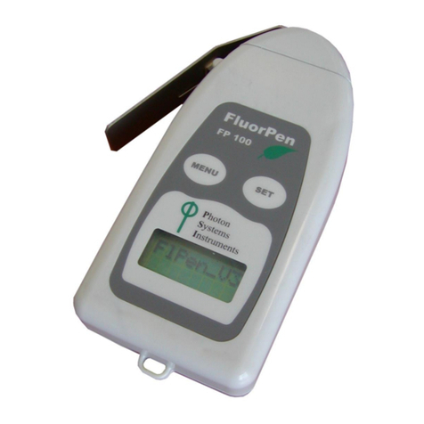
PSI FluorPen FP 110 Manual


Page | 2
Manual Version: 2021/12
© PSI (Photon Systems Instruments), spol. s r.o.
www.psi.cz
This document and its parts can be copied or provided to a third party only with the express permission of PSI.
The contents of this manual have been verified to correspond to the specifications of the device. However, deviations cannot be ruled out.
Therefore, a complete correspondence between the manual and the real device cannot be guaranteed. The information in this manual is
regularly checked, and corrections may be made in subsequent versions.
The visualizations shown in this manual are only illustrative.
This manual is an integral part of the purchase and delivery of equipment and its accessories and both Parties must abide by it.

Page | 3
TABLE OF CONTENT
1Information before using FluorPen device........................................................................................................ 5
2General Description ......................................................................................................................................... 6
2.1 Technical Specification..............................................................................................................................................8
3Device Description ......................................................................................................................................... 11
3.1 List of equipment and customer information..........................................................................................................12
3.2 Care and maintenance............................................................................................................................................12
4Principle of measurement.............................................................................................................................. 13
5Getting started............................................................................................................................................... 15
5.1 Pulses description and setting ................................................................................................................................15
5.2 Measurement .........................................................................................................................................................18
5.3 Protocols explanation .............................................................................................................................................18
5.3.1 OJIP protocol ..........................................................................................................................................................18
5.3.2 Non-photochemical quenching (NPQ) protocols....................................................................................................20
5.3.3 Light curve (LC) protocols .......................................................................................................................................23
5.4 Multiple measurement ...........................................................................................................................................26
6Control menu tree.......................................................................................................................................... 27
7USB Connection ............................................................................................................................................. 35
8Bluetooth connection..................................................................................................................................... 36
8.1 Bluetooth pairing....................................................................................................................................................36
9FluorPen software.......................................................................................................................................... 39
9.1 Software installation...............................................................................................................................................39
9.2 Menu and icons explanation...................................................................................................................................40
9.2.1 Main menu .............................................................................................................................................................40
9.2.2 Menu settings.........................................................................................................................................................41
9.2.3 Menu online control...............................................................................................................................................41
9.3 Data transfer and visualization...............................................................................................................................44
9.4 Firmware update ....................................................................................................................................................46
10 GPS module ................................................................................................................................................... 48
10.1 GPS/FluorPen operation .........................................................................................................................................48
10.2 Data download .......................................................................................................................................................48
11 Warranty terms and conditions...................................................................................................................... 50

Page | 4
12 Troubleshooting and Customer Support......................................................................................................... 50
13 Appendix ....................................................................................................................................................... 51
13.1 Battery pack for Monitoring Pen ............................................................................................................................51
13.1.1 Standard battery pack ............................................................................................................................................51
13.1.2 Extended temperature range battery pack ............................................................................................................52
13.2 Installation and operation of the Monitoring Pen MP 100-A/B..............................................................................53
13.2.1 Device control.........................................................................................................................................................53
13.2.2 Device installation ..................................................................................................................................................55
13.3 Detachable leaf clips...............................................................................................................................................55

Page | 5
1INFORMATION BEFORE USING FLUORPEN DEVICE
Read this manual carefully before operating the device. If you are not sure about something in the manual, contact the manufacturer for
clarification.
By accepting the device, the customer agrees to follow the instructions in this guide.
Always follow corresponding manuals while working with the FluorPen device or doing the maintenance.
It is forbidden to interfere with the hardware or software of the FluorPen device in any way without previous agreement with the
manufacturer.
The following table presents basic highlight symbols used in this manual:
Symbol
Description
Important information, read carefully.
Complementary and additional information.
Table 1 Used symbols.

Page | 6
2GENERAL DESCRIPTION
FluorPen FP 110 is a portable, battery-powered fluorometer that enables quick and precise measurement of chlorophyll fluorescence
parameters (Ft, QY, NPQ, OJIP, and LC of (QY) in plants. The FluorPen can be used in the laboratory, greenhouse, or in the field, where
data can be mapped precisely to the location with the built in GPS module. With the built-in GPS module, the FluorPen is a great device
for studying photosynthetic activity, stress detection, herbicide testing, or mutant/variety/transgenic screening in the field. Affordable
price and user-friendly two-button operation make the FluorPen a perfect tool for teaching photosynthesis. Because of its rapid
measurement capability and large internal memory, the FluorPen is also an invaluable tool for large plant-screening programs.
PAR-FluorPen FP 110 includes all features of the FluorPen FP 110, and measures the same chlorophyll fluorescence parameters as FP110,
but in addition, the PAR-FluorPen has an integrated Light Meter for direct digital readouts of Photosynthetically Active Radiation (PAR)
in the range from 400 to 700 nm. PAR is measured as Photosynthetic Photon Flux Density (PPFD), which is indicated by units of quanta
(photons) per unit time per unit surface area. The sensor has a uniform response to photons in the 400-700 range. Instant readouts are
provided as average values of 20 measurements. It is recommended to recalibrate the PAR sensor every 2 years.
Monitoring Pen MP 100 is a lightweight, portable and a more durable version of the FluorPen. It is designed for long-term, unattended
monitoring of chlorophyll fluorescence parameters in the field or lab experiments. It features weatherproof construction for use even in
adverse environmental conditions, or in the laboratory /greenhouse long term experiments. It is battery operated (internal or external
battery) and as an option may be used with a solar panel as a power supply.
All measured data are sequentially stored in the internal memory of the FluorPen, PAR-FluorPen or Monitoring Pen all collected data can
be transferred from the devices to the PC computer via both USB and Bluetooth communication -. Comprehensive FluorPen 1.1 software,
included with the device provides data transfer, and visualization protocols.
Unless stated otherwise, the information regarding the FluorPen FP 110 is relevant also to PAR FluorpenFP110
and the Monitoring Pen MP 100.
FluorPen versions:
FluorPen FP 110/S
Equipped with a standard attached leaf-clip.
FluorPen FP 110/D
Adapted for use with detachable leaf-clips; leaf clips sold separately in sets of 10.
FluorPen FP 110/P (Fig. 1c)
Intended for autonomous use in indoor conditions (previously Monitoring Pen-S). It features a
plastic case, measuring probe and thread for tripod attachment.
FluorPen FP 110/X
The “X“ version is mounted with custom-made leaf-clip.
PAR-FluorPen FP 110/S (Fig. 1a)
Same features as the standard FluorPen FP 110/S plus Photosynthetically Active Radiation (PAR)
meter in the range from 400 to 700 nm. equipped with a standard leaf-clip.
PAR-FluorPen FP 110/D (Fig. 1b)
Same features as the FluorPen FP 110/D adapted for use with detachable leaf clips plus
Photosynthetically Active Radiation (PAR) meter in the range from 400 to 700 nm. Leaf clips sold
separately.
PAR-FluorPen FP 110/X
Same features as the PAR-FluorPen FP 110/D but the “X“ version is mounted with custom-made
leaf-clip.

Page | 7
Fig. 1 a) PAR-FluorPen FP 110/S. b) PAR-FluorPen FP 110/D. c) FluorPen FP 110/P.
Monitoring Pen versions:
Monitoring Pen MP 100-E (Fig. 2a)
Monitoring Pen MP 100-E is a modified FluorPen designed for extra durability, battery-powered and intended for autonomous use in
field conditions during extended experiments. It features waterproof metal case, measuring probe, thread for tripod attachment,
external pack with batteries and the FluorPen 1.1 software for data collection and processing.
Monitoring Pen MP 100-A (Fig. 2b)
This is a submersible, battery-powered FluorPen intended for underwater measurements of chlorophyll fluorescence parameters (also
autonomous). It features a waterproof case, measuring probe, and the FluorPen 1.1 software for data collection and processing. External
battery pack with batteries is sold separately. This aquatic version of the monitoring pen is intended for use at maximum water depth of
2 meters. The device is equipped with two buttons that allow direct control of the device (even under water). A customized Version B of
this instrument is also available for use in deeper water (maximum 10 m). There are no control buttons on this version of the device.
Version B is controlled via software and a PC (placed above water). The device is usually fixed in static position under water.
Fig. 2 a) Monitoring Pen MP 100-E. b) Monitoring Pen MP 100-A.

Page | 8
2.1 TECHNICAL SPECIFICATION
FluorPen and PAR-FluorPen
Protocols
Ft –instantaneous chlorophyll fluorescence
Quantum Yield
OJIP
Non-photochemical quenching
Light curve
Photosynthetically Active Radiation (measured as PPFD) –PAR-FluorPen only
LED emitter
Blue (470 nm), other wavelengths on request
Saturating pulse Illumination
Up to 3,000 µmol(photon).m-2.s-1 (adjustable from 10 to 100%)
Actinic Illumination
Adjustable from 10 to 1,000 µmol(photon).m-2.s-1
Measuring Illumination
Up to 0,09 µmol(photon).m-2.s-1 per pulse (adjustable from 10 to 100%)
Detector
PIN photodiode with bandpass filters
Wavelength range from 667 to 750 nm
Internal memory capacity
Up to 16 Mb
Internal data logging
Up to 149,000 measurements (depending on protocol)
Data transfer
USB cable
Bluetooth (transfer up to 3Mbps for distance up to 20m)
PC software
FluorPen 1.1 (Windows 7 and higher)
Battery
Li-Ion rechargeable battery
Capacity 2000 mAh
Max. charging current 0.5 A
Charging via USB port - PC, power bank, USB charger, etc.
48 hours typical with full operation
Low battery indicator
Sample holder
Standard leaf-clip (FP 110/S)
Detachable leaf-clip (FP 110/D)
Probe (FP 110/P)
Display
Graphical display
Keypad
Sealed, 2-key tactile response
Turns off after 5 minutes of no use
Built in GPS module
Ultra-high sensitivity down to -165dBm
High accuracy of <1.5 m in 50% of trials
Size
134 x 65 x 33 mm
Weight
188 g
Operating conditions
Temperature: 0 to +55 °C
Relative humidity: 0 to 95 % (non-condensing)
Storage conditions
Temperature: -10 to +60 °C
Relative humidity: 0 to 95 % (non-condensing)
Warranty
1-year parts and labor

Page | 9
Monitoring Pen
Protocols
Ft –instantaneous chlorophyll fluorescence
Quantum Yield
OJIP
Non-photochemical quenching
Light curve
LED emitter
Blue (470 nm), other wavelengths on request
Saturating pulse Illumination
Up to 3,000 µmol(photon).m-2.s-1 (adjustable from 10 to 100%)
Actinic Illumination
Adjustable from 10 to 1,000 µmol(photon).m-2.s-1
Measuring Illumination
Up to 0,09 µmol(photon).m-2.s-1 per pulse (adjustable from 10 to 100%)
Detector
PIN photodiode with bandpass filters
Wavelength range from 667 to 750 nm
Internal memory capacity
Up to 16 Mb
Internal data logging
Up to 149,000 measurements (depending on protocol)
Data transfer
Serial cable
PC software
FluorPen 1.1 (Windows 7 and higher)
External Battery
Standard battery pack
operating temperature from 10 to 40 °C
rechargeable
Extended temperature range battery pack
operating temperature from -40 to 60 °C
non-rechargeable (spare battery)
Capacity 12Ah
Battery life up to 2 years of operation (1 QY measurement per hour)
Sample holder
Probe
Display
2 x 8 characters LC display
Keypad
Sealed, 2-key tactile response
Turns off after 5 minutes of no use
Built in GPS module
Ultra-high sensitivity down to -165dBm
High accuracy of <1.5 m in 50% of trials
Size
134 x 65 x 33 mm
Weight
188 g
Warranty
1-year parts and labor

Page | 10
Bluetooth module compliance data:
Category
Country
Standard
Radio
USA
FCC Part 15 Subpart B: 2008 Class B
FCC CRF Title 47 Part 15 Subpart C
FCC ID:
T9J-RN42
Europe
ETSI EN 301 489-1 V1.8.1
ETSI EN 301 489-17 V2.1.1
ETSI EN 300 328 V1.7.1
Canada
IC RSS-210 low power comm. device
Certification number:
6514A-RN42
EMC
USA
FCC CFR47 Part 15 subclass B
Europe
EN 55022 Class B radiated
EN61000-4-2 ESD immunity
EN61000-4-3 radiated field
EN61000-4-6 RF immunity
EN61000-4-8 power magnetic immunity

Page | 11
3DEVICE DESCRIPTION
Fig. 3 Device description.

Page | 12
3.1 LIST OF EQUIPMENT AND CUSTOMER INFORMATION
Carefully unpack the carton. You should have received the following items:
•FluorPen/Monitoring Pen
•Carrying Case
•Textile Strap for Comfortable Wearing
•FluorPen Operating Manual (on a USB flash disc)
•FluorPen software and driver (on a USB flash disc)
•USB cable
•Self-Adhesive Rubber Pads for Optics Protection (FP 110/S only)
•Detachable Leaf-clips (FP 110/D only and sold separately)
Other Accessories or Optional Features (according to your specific order)
For data download via USB connection, the USB driver needs to be installed on the PC. It can be found on the
installation disk (USB driver folder).
If any item is missing, please, contact the manufacturer. Also check the carton for any visible external damage. If
any damage is found, notify the carrier and the manufacturer immediately. The carton and all packing materials
should be retained for inspection by the carrier or insurer.
For customer support, please write to: [email protected]
3.2 CARE AND MAINTENANCE
FluorPen and Monitoring Pen
•Never submerge the device in water! (except Monitoring Pen MP 100-A).
•The device should not come in contact with any organic solvents, strong acids or bases.
•Keep the optical part clean and dry. If cleaning is needed, use soft, non-abrasive tissue.
•Battery charge lasts approximately 48 hours when the FluorPen is operated continuously.
•If the battery can no longer be charged please contact PSI for replacement battery and installation instructions.
Li-ion battery
•Avoid fully discharging of the battery.
•Do not keep the battery at full charge for all the time.
•Keeping at high temperatures shortens battery life.

Page | 13
4PRINCIPLE OF MEASUREMENT
FluorPen is a chlorophyll fluorometer and is used to measure different photosynthetic parameters in plants. It is equipped with a blue
LED emitter (470 nm), optically filtered and precisely focused to deliver light intensities of up to 3,000 µmol.m-2.s-1 to measured plant
tissue (Fig. 4).
When studying photosynthesis using chlorophyll fluorescence, researchers must distinguish between photochemical quenching and non-
photochemical quenching (heat dissipation). This is achieved by stopping photochemistry, which allows researchers to measure
fluorescence in the presence of non-photochemical quenching alone. To reduce photochemical quenching to negligible levels, a high
intensity, short flash of light is applied to the leaf. This transiently closes all PSII reaction centers, which prevents energy of PSII being
passed to downstream electron carriers. Non-photochemical quenching will not be affected if the flash is short. During the flash, the
fluorescence reaches the level obtained in the absence of any photochemical quenching, known as maximum fluorescence Fm. The
efficiency of photochemical quenching (which is a proxy of the efficiency of PSII) can be estimated by comparing Fmto the steady yield
of fluorescence in the light Ftand the yield of fluorescence in the absence of photosynthetic light F0. The efficiency of non-photochemical
quenching is altered by various internal and external factors. Alterations in heat dissipation result in changes in Fm. Heat dissipation
cannot be totally stopped, so the yield of chlorophyll fluorescence in the absence of non-photochemical quenching cannot be measured.
See picture below (Fig. 5). When measuring Fm it is important to dark adapt the samples. This can be achieved by placing the sample in
the dark for few minutes (the time varies with conditions) or by using the FP110/D version of the FluorPen that has been adapted for
detachable leaf clips. The leaf clips may be placed on the leaf ahead of the measurements and once dark adaptation has been achieved
the FP-110/D may be attached to the leaf clip without exposing the leaf to light.
Fig. 4 Fluor Pen FP 110/S.

Page | 14
Fig. 5 Chlorophyll fluorescence.
FluorPen measures:
Ft - Instantaneous Chlorophyll Fluorescence
Ftis equivalent to F0 if the sample is dark-adapted.
QY - Quantum Yield
QY is a measure of the Photosystem II efficiency. QY is equivalent to Fv/Fmin dark-adapted samples and to Fv ' /Fm ' in light-adapted
samples.
OJIP - Chlorophyll Fluorescence Induction Kinetics
The OJIP curves show major changes that occur during exposure of a sample to high irradiance (see more in chapter 5.3.1).
NPQ - Non-Photochemical Quenching
The NPQ protocol is used to quantify photochemical and non-photochemical quenching. The measurement should be performed
with a dark-adapted sample. (see more in chapter 5.3.2).
LC - Light Curve
Photosystem II Quantum Yield estimated from fluorescence that is measured sequentially at several different light levels. More in
chapter 5.3.3.
PAR - Photosynthetically Active Radiation (PAR-FluorPen only)
Photosynthetically Active Radiation measured as Photosynthetic Photon Flux Density (PPFD).

Page | 15
5GETTING STARTED
For more detailed information on particular steps of FluorPen operation please refer to chapter 6.
The device can is powered with built in Li-Ion battery. Ensure the battery is fully charged by plugging it into a PC via USB cable or the
AC outlet via the USB cable and a USB adaptor (not included). Monitoring Pen can be powered from an optional battery pack (see more
in chapter 13.1).
The FluorPen is controlled using two buttons:
•Use the MENU key to scroll through sequential menu options on the digital display and to turn the device off (hold for 3 s).
•Use the SET key to turn the device on (hold for 1 sec) and select a menu option based on cursor (>) position.
5.1 PULSES DESCRIPTION AND SETTING
Flash pulse
This function serves for setting of measuring pulses intensity. The measuring pulses are weak light pulses, which are able to induce the
minimal chlorophyll fluorescence (F0or Ft). It takes only 30 µs and the maximum intensity is
3,000 µmol.m-2.s-1. It means 30 µs * 3,000 µmol.m-2.s-1 = 0.09 µmol.m-2 per pulse is the maximal intensity of the flash pulse.
Super pulse
This function serves for setting intensity of the saturating pulse. Saturating light pulse is able to induce maximum chlorophyll fluorescence
(Fm). 100% of intensity represents approximately 3,000 µmol.m-2.s-1.
Actinic pulse
This function serves for setting intensity of actinic light. It is the ambient light in which the plants are growing. 100% of intensity equals
approximately 1,000 µmol.m-2.s-1.
Pulses used in predefined protocols:
Measurements based on fluorescence
Used pulses
Ft
Flash pulse
QY
Flash pulse, Super pulse
OJIP
Super pulse
NPQ protocols
Flash pulse, Super pulse, Actinic pulse
Light Curves
Flash pulse, Super pulse (Actinic pulse is preset)

Page | 16
Default setting of light color and intensities in FluorPen firmware. These may be changed according to user requirements and
samples growth conditions:
Flash pulse 30% = Measuring flash pulse
Super pulse 80% = Saturating pulse
Actinic pulse 300 µmol.m-2.s-1 (30 %) = Actinic light
Please note that those parameters are recommended by manufacturer and can be change according to user
needs.
Setting of optimal intensities of pulses:
Flash pulse setting
The optimum value of Flash pulse can be determined with QY measurement as shown in Fig.6 below. Before performing QY measurement
it is recommended to set the intensity of Super pulse to 80 %.
Please note that QY measurement should be performed with dark adapted sample, therefore the same sample (position on the leaf)
should not be used more than once unless dark adaptation follows the first measurement. The recommendation is to use a new sample
(new area on the leaf) for each QY measurements.
F0increases linearly with growing intensity of the Flash pulse.
The Flash pulse setting recommended by manufacturer is 30 %.
One can increase the intensity of Flash pulse for samples with
very low chlorophyll density. However, it should be noted that
high intensities of Flash pulse can cause undesirable “actinic
effect” as higher intensity High Flash pulse will initiate the
photochemistry. Changes in the Flash pulse will affect F0and the
QY value will be lower.
The optimal Flash pulse intensity is that at which the highest
value of QY is reached. This can be easily determined on one leaf
by measuring QY in few different spots with different flash pulse
settings. See (Fig. 6) below. In this example the optimal flash
pulse setting is 30%.
Super pulse setting
To determine the optimal intensity of Super pulse is to perform OJIP measurement with different Super pulse settings.
Please note that OJIP measurement should be performed with dark adapted sample. New sample (new section of the same leaf) should
be used for every measurement as exposure to super pulse will change photochemistry of the leaf in that section.
The Super pulse setting recommended by manufacturer is 80 %.
When performing the OJIP measurement with different intensities of Super pulse the Fv/Fm value will stop increasing when the optimal
level has been reached for the samples used (Fig. 7 and Fig. 8).
Fig. 6 QY measurement performed with different intensities of Flash pulse.
Optimal setting is highlighted in red rectangle.

Page | 17
Fig. 7 OJIP measurement performed with different intensities of Super pulse.
Fig. 8 OJIP data - measurement performed with different intensities of Super pulse. The highest Fv/Fm value indicates the optimal intensity of Super
pulse (20% in this case).

Page | 18
Actinic pulse setting
Intensity of Actinic pulse should correspond with cultivation light intensity or should be set according to application.
Should Overflow be observed on the display during the measurement, lower the intensity of the used pulses.
In case of Low value on display during measurement, increase the intensity of the used pulses.
5.2 MEASUREMENT
No device calibration is needed before chlorophyll fluorescence measurements are made. Results of fluorescence measurement depend
on device settings and the samples.
How to perform Chlorophyll Fluorescence measurement with FluorPen:
•Prepare dark adapted sample first (prior to F0, QY, NPQ, LC measurements) by placing the sample for at least 10-15 min in the dark.
Alternatively, dark adaptation can be easily achieved by placing the detached leaf clips in closed position on the leaf ahead of the
measurements. Only the FP110/D or PAR-FP110/D is designed for use with the detachable leaf clips. The duration of dark-adaptation
period depends on plant species and growth conditions.
•For light adapted measurements no dark adaptation of the sample is required.
•Turn ON the device by holding the SET button for 1 sec.
•Place the dark-adapted leaf in the leaf-clip (FP110/S or PAR-FP110/S) or in case of detachable leaf clips place the leaf clip on the
optical probe of the FluorPen and slide open the screen of the leaf clip to expose the leaf to the optical probe.
•Select Measure > from the menu and select required parameter for example –QY (press SET as Enter button when making
selections).
•Press SET to start the measurements.
•When OJIP, LC or NPQ are being measured the display on the device shows the progress of the measurement as percentage.
•When Ft or QY are measured the values appear on the device display. The result of OJIP, NPQ or LC protocol are not visible on the
display of the device and need to be download to PC computer (via USB cable or BT connection, see instructions in Chapter 7 and 8)
using FluorPen Software (downloaded to PC earlier).
•All measured data are stored in the device memory and can be downloaded to PC computer after completion of the experiment.
5.3 PROTOCOLS EXPLANATION
5.3.1 OJIP PROTOCOL
The FluorPen device offers the protocol to capture rapid fluorescence transient –OJIP, which occurs during exposure of photosynthetic
organisms to high irradiance. The FluorPen software enables data downloading to a PC and subsequent OJIP curve and calculated data
visualization.

Page | 19
The OJIP protocol includes the following measured and calculated parameters:
Abbreviation
Explanation
Bckg
Background
F0
F0= F50µs, fluorescence intensity at 50 µs
Fj
Fj = fluorescence intensity at J-step (at 2 ms)
Fi
Fi = fluorescence intensity at i-step (at 30 ms)
Fm
Fm= maximal fluorescence intensity
Fv
Fv= Fm - F0(maximal variable fluorescence)
Vj
Vj= ( Fj- F0 ) / ( Fm - F0 )
Vi
Vi= ( Fi- F0 ) / ( Fm - F0 )
Fm/ F0
FV/ F0
Fv/ Fm
M0 or (dV/dt)0
M0 = TR0 / RC - ET0 / RC = 4 ( F300 - F0 ) / ( Fm - F0 )
Area
Area between fluorescence curve and Fm (background subtracted)
Fix Area
Area below the fluorescence curve between F40µs and F1s (background subtracted)
SM
SM= Area / ( Fm - F0 ) (multiple turn-over)
SS
SS= the smallest SMturn-over (single turn-over)
N
N = SM. M0. ( 1 / VJ ) turn-over number QA
Phi_P0
Phi_P0 = 1 –( F0 / Fm) (or Fv/ Fm)
Psi_0
Psi_0 = 1 - VJ
Phi_E0
Phi_E0 = ( 1 –( F0/ FM )) . Psi_0
Phi_D0
Phi_D0= 1 –Phi_P0 = ( F0/ Fm )
Phi_Pav
Phi_Pav = Phi_P0 ( SM / tFm ) tFm = time to reach Fm(in ms)
ABS / RC
ABS / RC = M0. ( 1 / VJ ) . (1 / Phi_P0 )
TR0 / RC
TR0 / RC = M0. ( 1 / VJ )
ET0 / RC
ET0 / RC = M0. ( 1 / VJ ) . Psi_0
DI0 / RC
DI0 / RC = ( ABS / RC ) –( TR0 / RC )
Formulas Derived From:
R.J. Strasser, A. Srivastava and M. Tsimilli-Michael (2000): The fluorescence transient as a tool to characterize and screen photosynthetic
samples. In: Probing Photosynthesis: Mechanism, Regulation and Adaptation (M. Yunus, U. Pathre and P. Mohanty, eds.), Taylor and
Francis, UK, Chapter 25, pp 445-483.

Page | 20
5.3.2 NON-PHOTOCHEMICAL QUENCHING (NPQ) PROTOCOLS
The NPQ protocol is used to quantify photochemical and non-photochemical quenching. It should be performed with dark-adapted
samples. The NPQ protocol starts with measurement of minimal level of fluorescence F0during a dark period.A short saturating flash of
light is then applied to reduce the plastoquinone pool and measure maximum fluorescence in the dark-adapted state, Fm. After a short
dark relaxation, the sample is exposed to actinic irradiance for tens to hundreds of seconds to elicit a transient called the Kautsky effect.
A sequence of saturating flashes is then applied during exposure to actinic light to probe the non-photochemical quenching NPQ and
effective quantum yield of photosynthesis QY in light adapted state. After exposure to continuous illumination, the relaxation of non-
photochemical quenching is determined by means of saturating pulses applied in dark. This sequence of the protocol is illustrated in Fig.
9.
The FluorPen device comes with three predefined NPQ protocols, NPQ1, NPQ2 and NPQ3. The protocols differ in the duration of the light
exposure and the dark recovery phase, and in the number and interval between pulses. See Table 2:
Phase
Duration
# of pulses
1st pulse
Pulse interval
NPQ1
Light
60 s
5
7 s
12 s
Dark recovery
88 s
3
11 s
26 s
NPQ2
Light
200 s
10
10 s
20 s
Dark recovery
390 s
7
20 s
60 s
NPQ3
Light
200 s
10
11 s
21 s
Dark recovery
60 s
2
20 s
21 s
Table 2 NPQ Protocols.
The NPQ protocols include the following measured and calculated parameters:
Abbreviation
Explanation
F0
minimum fluorescence in dark-adapted state
Fm
maximum fluorescence in dark-adapted state, measured during the first saturation flash after dark
adaptation
Fp
fluorescence in the peak of fast Kautsky induction
Fm_Ln, Lss, D, Dn1
maximum fluorescence
QYmax2
maximum quantum yield of PSII in dark-adapted state - Fv/Fm
QY_Ln, Lss, D, Dn1,3
effective quantum yield of PSII
NPQ_Ln, Lss, D, Dn1,4
non-photochemical chlorophyll fluorescence quenching
Qp_Ln, Lss, D, Dn1,5
coefficient of photochemical quenching, an estimate of open PSII reaction centers
1 L- indicates light adapted parameters; D- refers to dark recovery phase after switching of the actinic illumination; n- represents a
sequential number of light phases; ss - steady state
2 Calculated as (Fm–F0) / Fm
3Calculated as (Fm_Ln –Ft_Ln) / Fm_Ln or of corresponding steady state or dark recovery parameters
4 Calculated as (Fm–Fm_Ln) / Fm_Ln or of corresponding ss, Dn or Dss parameters
5 Calculated as (Fm_Ln –Ft_Ln) / (Fm_Ln –F0_Ln) or of corresponding ss, Dn or Dss parameters
Other manuals for FluorPen FP 110
1
This manual suits for next models
2
Table of contents
Other PSI Measuring Instrument manuals
Popular Measuring Instrument manuals by other brands

Pentax
Pentax TH-10 Instruction book

Crossbow Technology
Crossbow Technology AHRS400 Series user manual
KRAL
KRAL OMG Series operating instructions
Hanna Instruments
Hanna Instruments HI 93700 instruction manual
Apogee Instruments
Apogee Instruments SI-121-SS owner's manual
Tektronix
Tektronix VM700T instructions
