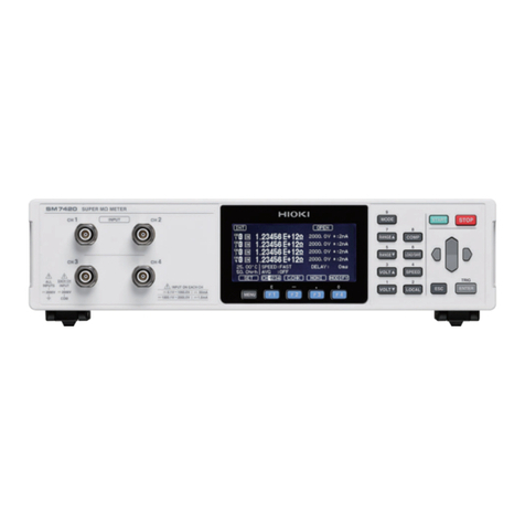
Hioki 3227 User manual

INSTRUCTION MANUA
L
For...は専用機種。複数の場合は「/」で区切る。不要の場合はとる
。
形名を入力。 複数の場合は「/」で区切る
。
322
7
品名を入力
。
mΩHiTESTE
R


Contents
Introduction i
Inspection i
Safety Notes ii
Notes on Use iv
Organization of this Manual vi
Chapter 1 Overview 1
1.1 Features 1
1.2 Specifications 2
1.2.1 General Specifications 2
1.2.2 Resistance Measurement 4
1.2.3 Temperature Measurements 5
1.2.4 Temperature Correction Function 5
1.3 Measurements and Working Systems 6
1.3.1 4-terminal Measurements 6
1.3.2 Temperature Probe 7
1.3.3 Measurement Value Display 10
1.3.4 Comparator Function 12
Chapter 2 Part Names 15
2.1 Front Panel 15
2.2 Rear Panel 16
2.3 Displays 17
2.4 Accessory and Options 18
Chapter 3 Unit Installation 19
3.1 Installing the Interfaces 19
3.2 Turning on the Power Supply 21
3.3 Selecting the Power Supply Frequency 23
3.4 Preparation for Measurements 24
3.4.1 Resistance Measurements 24
3.4.2 Temperature Correction and Temperature Measurements
25
3.5 Handle Operation 26

Chapter 4 Basic Operations 27
4.1 Operating Procedure 27
4.1.1 Function Classes 27
4.1.2 Key Shift States 28
4.1.3 Key Lock State 28
4.1.4 Remote State 28
4.1.5 Valid Input Key Table 29
4.2 Selecting the Measurement Mode 30
4.3 Resistance Measurement Mode 31
4.3.1 Selecting the Sampling Rate 31
4.3.2 Selecting the Measuring Range 32
4.3.3 Zero Adjustment 34
4.4 Resistance Measurement 35
4.5 Temperature Measurement 36
4.6 Holding the Measurement Value 37
Chapter 5 Applied Operations 39
5.1 Setting the Comparator 39
5.1.1 Setting the Comparator 1 39
5.1.2 Setting the Comparator 2 41
5.1.3 Eliminating the Comparator Table 42
5.2 Executing the Comparator 43
5.3 Setting the Temperature Correction 44
5.4 Executing the Temperature Correction 45
5.5 Setting the Temperature Conversion 46
5.6 Executing the Temperature Conversion 47
Chapter 6 External Control Terminals 49
6.1 Connector 49
6.1.1 Terminal Block 49
6.1.2 Digital I/O 50
6.2 Connecting Method 51
6.2.1 Terminal Block 51
6.2.2 Digital I/O 51
6.3 Electrical Specifications 53
6.3.1 Power Supply Rating 53
6.3.2 Input and Output Rating 53
6.3.3 Input and Output States 54

6.4 Using the Signals 58
6.4.1 Measurement Control 58
6.4.2 Outputting Measurement Results 61
Chapter 7 The Other Functions 63
7.1 System Resetting 63
7.2 Error Indications 64
Chapter 8 GP-IB Interface 67
8.1 Specifications 67
8.2 Setting the GP-IB Address 68
8.3 Introduction for the GP-IB 69
8.3.1 Messages 69
8.3.2 Command Syntax 70
8.3.3 Headers 70
8.3.4 Message Terminators 71
8.3.5 Separators 71
8.3.6 Data Formats 72
8.3.7 Abbreviation of Compound Command Type Header 73
8.3.8 Output Queue 73
8.3.9 Input Buffer 74
8.3.10 Status Model 74
8.3.11 Status Byte Register 75
8.3.12 Event Register 76
8.3.13 GP-IB Commands 78
8.4 Command Reference 79
8.5 Command Summary 109
8.5.1 Standard Command 109
8.5.2 Commands Specific to the 3227 110
8.6 Valid Command According to the Modes 113
8.7 Initialization 114
8.8 Notes on GP-IB Interface 115
8.9 Sample Programs 116
8.9.1 Hewlett Packard Series 300 Sample Programs 116
8.9.2 DOS/V Sample Program 124

Chapter 9 Printer Interface 127
9.1 Printer Interface 127
9.1.1 Connecter 127
9.1.2 Connecting Method 128
9.2 Print Method 129
Chapter 10 Maintenance and Service 131
10.1 Changing the Fuse 131
10.1.1 Power Fuse 131
10.1.2 Circuit Protection Fuse 132
10.2 Disposing the Unit 134
10.3 Trouble Shooting 135

i
────────────────────────────────────────────────────
Introduction
────────────────────────────────────────────────────
I
ntroduction
I
nspection
Thank you for purchasing this HIOKI "3227 mΩHiTESTER." To get the
maximum performance from the unit, please read this manual first, and keep
this at hand.
When the unit is delivered, check and make sure that it has not been
damaged in transit. In particular, check the accessories, panel switches, and
connectors. If the unit is damaged, or fails to operate according to the
specifications, contact your dealer or HIOKI representative.
Accessories
9287 CLIP TYPE LEAD 1
9188 TEMPERATURE PROBE 1
Power code 1
Converter plug 1
Instruction Manual 1
Spare fuse for the circuit protection F1.0A/250V 1
Spare fuse for the power supply 1
T0.5A/250V (at 100/110/120V)
T0.25A/250V (at 200/220/240V)
(The spare fuse is stored inside the AC power supply inlet, and is of a rating
appropriate to the actual operational voltage of the unit.)
Shipment
If reshipping the unit, preferably use the original packing.

ii
────────────────────────────────────────────────────
Safety Notes
────────────────────────────────────────────────────
WARNIN
G
This equipment is designed to according to IEC 348 Safety Standards,
and has been tested for safety prior to shipment. Incorrect measurement
procedures could result in injury or death, as well as damage to the
equipment. Please read this manual carefully and be sure that you
understand its contents before using the equipment. The manufacturer
disclaims all responsibility for any accident or injury except that resulting
due to defect in its product.
・This symbol is affixed to locations on the equipment where the
operator should consult corresponding topics in this manual
(which are also marked with the symbol) before using relevant
functions of the equipment.
・In the manual, this mark indicates explanations which it is
particularly important that the user read before using the
equipment.
Indicates AC (Alternating Current).
Indicates a fuse.
S
afety Notes
This Instruction Manual provides information and warnings essential for
operating this equipment in a safe manner and for maintaining it in safe
operating condition. Before using this equipment, be sure to carefully read the
following safety notes.
Safety symbols

iii
────────────────────────────────────────────────────
Safety Notes
────────────────────────────────────────────────────
WARNIN
G
Indicates that incorrect operation presents significant danger of
accident resulting in death or serious injury to the user.
CAUTIO
N
Indicates that incorrect operation presents possibility of injury to the
user or damage to the equipment.
NOTE Denotes items of advice related to performance of the equipment or
to its correct operation.
The following symbols are used in this Instruction Manual to indicate the
relative importance of cautions and warnings.

iv
────────────────────────────────────────────────────
Notes on Use
────────────────────────────────────────────────────
WARNIN
G
In order to prevent electric shock and short-circuit accidents, shut off
the power to the line to be measured before connecting the direct
connection voltage and current cables to the terminals.
Be sure to connect the input terminal, SENSE, or SOURCE terminals
correctly. Measurement which is attempted with the wiring connected
incorrectly may cause damage to the unit or a short-circuit.
Before turning on the power, make sure that the voltage of the power
supply being used matches the supply voltage indicated on the rear
panel of the unit.
The unit is constructed so as to be connected to a ground line via a
three-core power cord that is supplied with the unit.
In order to avoid electric shock, connect the unit to a properly grounded
(3-pin) outlet using the power cord provided. In addition, if using a
ground adapter, be absolutely sure to connect the green ground wire
which protrudes from the adapter to a ground line.
In order to avoid electric shock, if not connecting the unit to a properly
grounded (3-pin) outlet using the power cord provided, be sure to
connect the ground terminal to a proper ground.
The maximum permissible input is mentioned on specifictioins. Do not
measure voltage in excess of these limitations, as doing so may damage
the unit or cause an accident that might result in infuty or death.
CAUTIO
N
・To avoid damage to the unit, do not input a voltage or current exceeding the
rated maximum to the external input terminals.
・To avoid damage to the unit, do not input a voltge or current exceeding the
rated to the output terminal.
・To avoid damage to the unit, do not subject the equipment to vibrations or
shocks during transport or handling. Be especially careful to avoid dropping
the equipment.
・Before using the unit, make sure that the sheathing on the probes is not
damaged and that no bare wire is exposed. If there is damage, using the
unit could cause electric shock. Replace the probe with the specified 9287.
・The unit should always be operated indoors in a range from 0℃to 40℃and
80% RH or less. Do not use the unit in direct sunlight, dusty conditions, or in
the presence of corrosive gases.
・Do not measure the voltage applied point. Particularly, the 3227 would be
damaged by induced voltage when measuring soon after the temperature
rise test or the pressure test of the trans or the motor.
N
otes on Use
In order to ensure safe operation and to obtain maximum performance from
the unit, observe the cautions listed below.

v
────────────────────────────────────────────────────
Notes on Use
────────────────────────────────────────────────────
NOTE ・Always set the power supply frequency before measurement. When it has
been set incorrectly, inaccurate measurement would be performed. How to set
this, Section 3.3, "Selecting the Power Supply Frequency."
・Accurate measurement may be impossible in locations subject to strong
external magnetic fields, such as transformers and high-current conductors, or
in locations subject to strong external electric fields, such as radio
transmission equipment.
・For accurate measurement, allow the unit to warm up for 30 minutes before
starting the operation.
・In the source of current (SOURCE), there is a fuse for the circuit protection.
When it is ruptured, the measurement should be impossible.
・Do not use such relay as dealing with the small signals, for fear of breaking
the pellicle of the contact point.
・When the one that includes the L component such as the transformer for the
power supply a lot is measured a measured value may not stabilize.

vi
────────────────────────────────────────────────────
Organization of this Manual
────────────────────────────────────────────────────
O
rganization of this Manual
Chapter 1 Overview
Summary and features of the 3227
Chapter 2 Part Names
Description of part names
Chapter 3 Unit Installation
Preparation for measurements
Chapter 4 Basic Operations
Description of basic operations
Chapter 5 Applied Operations
Setting the comparator and the temperature correction
Chapter 6 External Control Terminals
Description of the external control terminals
Chapter 7 The Other Functions
System resetting and error indications
Chapter 8 GP-IB Interface
Specifications and commands of GP-IB
Chapter 9 Printer Interface
Use of the printer interface
Chapter 10 Maintenance and Service
Disposing and trouble shooting
Index

1
────────────────────────────────────────────────────
1.1 Features
────────────────────────────────────────────────────
Chapter
1
Overvie
w
1
.1 Features
(1) 10μΩ minimum high accuracy and high resolution resistance measurement,
by 4-terminal measurement
(2) High speed resistance measurement of 90 times/second in its top
(3) Connecting the temperature probe makes 0℃to 40℃temperature
measurement possible
(4) Auto range function is contained
(5) Measurement ranges can be selected from external control terminal.
(6) The components can be selected by the comparator. When changing the
measurement subjects, the 15 comparator tables set in advance make it
possible. They can also be selected by external control terminal.
(7) When connecting the temperature probe, the resistance temperature is able to
be corrected by optional temperature and resistance temperature coefficient.
(8) The temperature of the measured object can be displayed, by conversion from
the measured resistance. Either the temperature (t) or the temperature rise
(Δt) of the measured object can be selected for display.
A comparator can also be used to provide a pass/fail decision from the
displayed value.
(9) The unit can hold up to 15 sets (tables) of temperature conversions in memory.
The setting table can also be selected using the external control terminals.
(10) Trigger input, BCD output and comparator output make the unit match for
the line use.
(11) The measurement results can be printed with the 9203 DIGITAL PRINTER.
The results also can be shown as statistics. (option)
(12) Full remote control by GP-IB is possible (option).
(13) The measurement results can be printed to the centronics printer (option).

2
────────────────────────────────────────────────────
1.2 Specifications
────────────────────────────────────────────────────
1
.2.1 General Specifications
Measurement method and
operating method 4-terminal and dual integrator circuit
Maximum number of display digit
Resistance measurement "30000" 4 digit (3 digit when at FAST)
Temperature measurement "4000" 3 digit
Temperature conversion "±999.9" 4 digit
Sampling rate
Resistance measurement "SLOW" Approx. 4 times/second
"MEDIUM" Approx. 16 times/second
"FAST" Approx. 90 times/second
Temperature measurement Approx. 2 times/second
NOTE: When performing the comparator as reference value-per-range, in "FAST", the sampling rate
would be approximately 75 times/seconds
Response time
Resistance measurement "SLOW" Approx. 500 ms
"MEDIUM" Approx. 150 ms
"FAST" Approx. 50 ms
Auto range Contains (invalid when using the comparator)
Input over "OF" display
Comparator Set with each 15 table (selected by key operation and external
control)
Comparison method selection (HIGH/LOW, REF/%)
External control terminal mode selection (AUTO/EXT)
Buzzer mode selection (Hi/Lo, IN, OFF)
3-level (Hi, IN, Lo) fluorescent character display tube display,
external control output.
Temperature correction function Correctional temperature (0.00℃to 40.00℃,32F to 104 F)
Standard temperature (-10.0℃to 99.9℃,14F to 122 F)
Temperature coefficient (±9999ppm)
Optional settings are possible
Temperature conversion function Absolute temperature/temperature rise(Δt) selectable
initial resistance (0.00 mΩto 300.00 kΩ)
initial temperature ( −10.0 ℃to 99.9 ℃)
coefficient ( ±999.9)
Optional settings are possible
Maximum over load input 100 VDC or VAC rms (circuit protection by fuse)
1
.2 Specifications

3
────────────────────────────────────────────────────
1.2 Specifications
────────────────────────────────────────────────────
Dielectric strength
Between the case and the input
terminal 1.5 kVAC
Between the case and the powe
r
supply line 1.5 kVAC (sensitivity current: 5 mA)
Insulation resistance Between the case and the input terminal (for a minute)
Between the case and the power supply line (for a minute)
100 MΩor more
External control
Open corrector output BCD 5 digit, measurement end, NG, comparator result
TTL input measuring range, comparator table, measurement trigger, print
,
zero adjustment, comparator output, temperature conversion
table
External interface The 9588 GP-IB INTERFACE (IEEE 488.2) (option)
Printer interface 9589 CENTRONICS (option)
Operating temperature/humidity 0℃to 40℃(32 Fto104F), 80% RH or less (no condensation)
Storage temperature/humidity -10℃to 50℃(14 Fto122F), 80% RH or less (no condensation)
Power supply and power
consumption 100, 110, 120, 200, 220, 240 VAC (±10%, 250 V MAX), 50/60 Hz,
maximum 40 VA
Dimensions and mass 215W×80H×320D mm (8.46"W×3.15"H×12.6"D) (excluding
protrusions), approx. 3.0 kg (105.8 oz.)
NOTE ・The temperature correction function or the temperature conversion function is
selected when the unit is powered on, and only one of these functions can be
used at a time.
・When using the temperature conversion function, the comparator uses its own
table (High/Low only).
・Selection of the comparator table with the external interface constitutes a
temperature conversion table selection.
・Auto ranging is always used when the temperature conversion function is
used.

4
────────────────────────────────────────────────────
1.2 Specifications
────────────────────────────────────────────────────
1
.2.2 Resistance Measurement
Condition 23℃±5℃(73 F ±9 F), 80% RH or less (no condensation),
After zero adjustment
Pre-heating period 30 minutes
Accuracy assurance period 6 months
Table 1 4-1/2 digit (sampling rate:SLOW)
Range 300 mΩ3Ω30 Ω300 Ω3kΩ30 kΩ300 kΩ
Resolution 10 μΩ 100 μΩ 1mΩ10 mΩ100 mΩ1Ω10 Ω
Measurement
current 100 mA 10 mA 1mA 10 μA
Maximum
applied voltage 30 mV 300 mV 3V 300 mV 3V
Accuracy * ±0.1% rdg
.
±8 dgt. 0.08% rdg. ±3 dgt. ±0.1% rdg.±3dgt.
Temperature
coefficient (±0.01% rdg.±0.5 dgt.)/℃
Open-terminal
voltage 7.0 Vmax
* If the sampling rate is set to MEDIUM, add 3 dgt to the digit accuracy error.
Table 2 3-1/2 digit (sampling rate:FAST)
Range 300 mΩ3Ω30 Ω300 Ω3kΩ
Resolution 100 μΩ 1mΩ10 mΩ100 mΩ1Ω
Measurement
current 100 mA 10 mA 1mA
Maximum
applied voltage 30 mV 300 mV 3V
Accuracy ±0.2% rdg. ±5 dgt.
Temperature
coefficient (±0.01% rdg.±0.1 dgt.)/℃
Open-terminal
voltage 7.0 Vmax

5
────────────────────────────────────────────────────
1.2 Specifications
────────────────────────────────────────────────────
1
.2.3 Temperature Measurements
Temperature sensor Platinum resistance element
Dielectric strength 1000 VAC between the temperature sensor sheath and the
voltage terminal(-).
Accuracy assurance range 0.00℃to 40.00℃
Resolution 0.01℃
Accuracy ±0.5℃
Temperature coefficient ±0.02×(t-23)℃
t : environment temperature where the 3227 is located (℃).
1
.2.4 Temperature Correction Function
Temperature correction range 0.00℃to 40.00℃(32 F to 104 F)
Standard temperature range -10.0℃to 99.9℃(14 F to 212 F)
Resistance temperature coefficient
range -9999 ppm to 9999 ppm
Accuracy In the temperature correction, add the value obtained by the
expression below to the accuracy of the resistance measurement
.
±0.5α×100 (%)
1+α((t0.5) - t0)
t: Environment temperature
t0: Standard temperature
α: Resistance temperature coefficient
0.5: Temperature measurement accuracy

6
────────────────────────────────────────────────────
1.3 Measurements and Working Systems
────────────────────────────────────────────────────
1
.3.1 4-terminal Measurements
r2r4r3r1
I
Ohmmete
r
Resistance R0
Voltmeter
Constant current sourc
e
E0
E
Measurement Using the 4-terminal Method
1
.3 Measurements and Working Systems
Regular 2-terminal measurement measures even the value which includes the
resistance of the measurement leads or the terminal area. Particularly, when
measuring the low resistance, it is necessary to measure the value without
this resistance value. 4-terminal measurement is able to measure that value.
4-terminal measurement and 2-terminal measurement are explained as
follows. In the figure below, there is very big input impedance in the
voltmeter, and all of the current Iflows to the measured resistance R0. The r1
to r4means the resistance of the measurement leads or the contact resistance
of the terminal area.
All of the current Iflows to the measured resistance R0. Therefore, the
voltage drop of r3and r4become 0, and voltage E and the voltage drop E0of
each end of the measured resistance R0become equal. Accordingly, the
resistance measurement without influence of r1to r4becomes possible.

7
────────────────────────────────────────────────────
1.3 Measurements and Working Systems
────────────────────────────────────────────────────
r2r1
I
Ohmmete
r
Resistance R0
Constant current sourc
e
E
Voltmeter
Measurement Using the 2-terminal Method
1
.3.2 Temperature Probe
Shield cabl
e
Platinum film resisto
r
322
7
The Internal Circuit of the Temperature Probe
The current Iflows to the measured resistance R0and the wiring resistance r1
and r2. Therefore, the measuring voltage E can be obtained by E=I(r1+R0+r2),
and it would include the wiring resistance r1and r2.
The 9188 TEMPERATURE PROBE makes temperature measurement and the
temperature correction function easy. In this section, explain the principle of
them.
See Section 3.4.2, "Temperature Correction and Temperature Measurement",
for connecting the temperature probe.
(1) Temperature measurement
The internal circuit of the temperature probe is as follows.
The temperature probe uses the platinum film resistor which is changeable
according to the temperature, as the temperature sensor. This probe displays
the resistance value of that register, detected by the 3227, after converting it
to the temperature using the CPU.

8
────────────────────────────────────────────────────
1.3 Measurements and Working Systems
────────────────────────────────────────────────────
(2) Temperature Correction Function
The temperature correction function displays the optional temperature
coefficient resistance value after converting to the resistance value of the
optional temperature. The resistance depends on the ambient temperature,
and it is of little use to measure the resistance while ignoring this
temperature dependence.
In the following expression, the resistance value Rtand Rt0 corresponds to the
resistance value of t ℃and the measured subjects of t0℃(resistance
temperature coefficient in t0℃:αt0)
Rt=Rt0 ×{1+αt0 ×(t−t0)}
The 3227 obtains the correctional resistance value (Rt0) from calculating the
temperature measured by the temperature probe (t), the resistance value of
the measured subjects (Rt), the standard temperature (t0) and temperature
coefficient (αt0) by CPU.
For example, the resistance value of the copper wire that will be 100Ωunder
30℃would be followingly under 20℃.
Rt
Rt0 ={1+αt0×(t−t0)}
100
={1+(3930×10−6)×(30−20)}
=96.22
See Section 5.3, "Setting the Temperature Correction" and Section 5.4,
"Executing the Temperature Correction", for how to set and execute the
temperature correction. Also see "Reference Material" at the end of this
chapter.
(3) Temperature conversion function
The temperature conversion function uses the temperature dependence of the
resistance to convert measured resistance values to temperature values and
display them.
According to JIS C4004, the temperature rise can be derived by the resistive
method as follows: rt
Δt= r0(T +t0)−(T +t)
r0: coil resistance under cold conditions
rt: present coil resistance
t0: ambient temperature when measuring coil resistance under cold
conditions
t: present ambient temperature
T: constant (copper: 235, aluminum: 230)
Table of contents
Other Hioki Measuring Instrument manuals

Hioki
Hioki TM6102 Use and care manual

Hioki
Hioki CKT3548 User manual

Hioki
Hioki 3447-01 User manual

Hioki
Hioki MR8740T Instruction manual

Hioki
Hioki 3470 User manual

Hioki
Hioki 3532-50 User manual

Hioki
Hioki 3246-60 User manual

Hioki
Hioki PW3365-20 User manual

Hioki
Hioki FT3432-20 User manual

Hioki
Hioki LR8450 User manual