1
X100kPa
BOOST
2
1
0-1
STEPPING
GAUGE
0
0.5
-0.5
1.5
1
MULTI GAUGE -1
x100°C
x100kPa
BOOST
TEMP
0
0.5
-0.5
1.5
1
MULTI GAUGE -1
x100°C
x100kPa
BOOST
TEMP
WATER
TEMP
60
40
120
100
80
STEPPING
GAUGE 20
°C
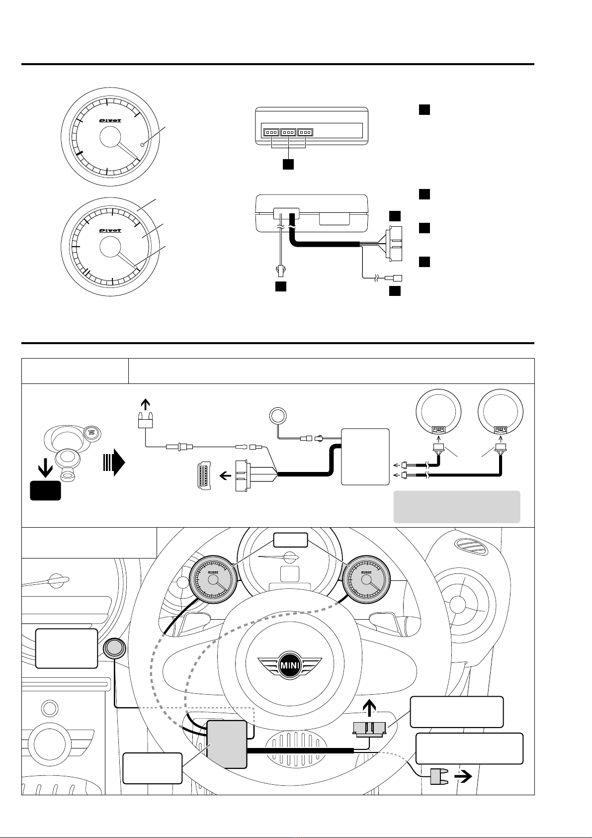
Features
Cushion
Tape
Cut
Connector
Meter Hood
User’s Manual
(This Book)
Zip Ties
× 2
Please check
the contents
of the package
Double-sided Tape
(square)
Double-sided Tapes
(round) × 4
(X2-M5 / 52X-BW December, 2014 No.3)
EURO SPEC
BOOST Meter
(Only 52X-BW)
(Only 52X-BW) (Only X2-M5)
(Only X2-M5)
(52X-BW × 2)
(52X-BW × 2)
Water Temp Meter Multi Gauge Server
(with OBD Connector)
Meter Cable
BOOST (Absolute pressure display*)
Displays and Uses
Display
Item
Example
Uses
[X2-M5]
-
100 ~150 kPa / [52X-BW]
-
100 ~154 kPa
• Check Boost • For Eco-driving [Vacuum] and so on
Water Temperature Opening Demo
[X2-M5]
-
40 °C ~150 °C / [52X-BW]20 °C ~ 120 °C
[X2-M5]70 kPa [52X-BW]
-
40 kPa [X2-M5]30°C [52X-BW]95°C
• Prevention of overheating • Check Heating and so on
* This display of absolute pressure includes barometric pressure and may differ from a meter showing relative pressure (mechanical type).
* With the key in the ON position, due to altitude the boost needle may show a minus reading.
During the Opening Demo,
the needle will move
slightly to minus several
times. Then it will move to
the maximum value and
finally to reading for current
measurement item.
Tap Screw
Fuse Power
Cable
Simple Connector Installation
Low-Priced
Meter Holder
Same Illumination
Switch
With our X2-M5 and 52X-BW, just by connecting to the diagnostic monitoring connector, the MINI specialized CAN communication can be
analyzed and two types of data can be simultaneously displayed. (Not for use with incompatible models)
Install by simply connecting to the diagnostic monitor connector and fuse box.
Metallic molded meter holder means reasonable pricing.
Newly designed lightweight meter holder with superior adhesion means less movement under vibration.
Uses same orange Illumination as that of standard meters.
The X2-M5 display switch is an easy-to install adhesive type.
If the boost limiter has been made inactive, the display may not function properly.
X2-M5 & 52X-BW
Switch
USER’S MANUAL
Easy-Connection Gauges for MINI 52X-BW
CAUTION
WARNING Improper use or disregard of these warnings may cause
injury to persons, damage the product and other things.
• Do not install the product in any
place subject to high temperature
or any place where water may be
splashed.
• Make sure to replace all screws and
parts to their original place.
• Do not install the product in a place
where it will cause distraction.
• Do not, in any manner, process,
take apart, or make changes to this
product.
• This product is for DC12V cars;
Installation cannot be carried out on cars with
other voltage batteries.
• Just after installation do not exert any
strong force on the product.
When double-sided tape is used for an installa-
tion be warned that when hot the tape tempo-
rarily losses adhesiveness.
• Do Not Use Chemical Cleansers.
If the unit gets dirty please wipe with a soft
cloth to remove any dirt. Do not use chemical
cleansers such as thinner, benzene, or alcohol.
• Do not work in areas where there
is excessive exhaust.
Due to vehicle exhaust emission poi-
soning or fire may result in a damage
to humans.
• Do not crush the cable.
Please be careful that the cable does
not get crushed by the seat rail or car
door steel plate, nor cut by any sharp
steel plate as this may cause a poor
connection or an electric short leading
to fire or other danger.
• Do not operate while driving.
Operating or checking the display
during driving may cause an acci-
dent; please use with the utmost
consideration for safety.
• Please securely fasten the
product to a stable placeand
be sure to store bundle away
all wires with tape, etc...
It is very dangerous to pull tangled
wires by force or allow tangled
wires to interfere with driving.
Thank you for purchasing this PIVOT product. Please read this manual carefully
before installation and use. Please keep this manual for future reference.
1. The display will not be proper if the ECU being used is not the standard one or if a sub-computer is being used, even
in compatible car models.
2. Cannot be used in combination with other company’s products that use Diagnostic Monitoring Connectors.
3. For details about using in combination with other PIVOT products that use Diagnostic Monitoring Connectors please
see our Web Site at http://pivotjp.com/obd-e/.
4. The meter hood can become extremely hot when exposed to direct sunlight; be particularly careful of burns.
Improper use or disregard of these warnings
may result in the injury or death of people.