Pixel SXMLCR72-VR1 User manual

SXMLCR72-VR1 - Roady BT Compact Motorcycle Kit
Installaon Instrucons
Pixel Technologies, Inc. | www.pixelsatradio.com | contact[email protected]m | (800) 595-0845 | Page 1
Package Includes
(1) SiriusXM™ Roady BT Display Controller
(1) Intelligent Power Adapter
(1) Handlebar Clamp Mount
(1) RAM Ball Mount Adapter (25 MM)
(1) Weatherproof Protecve Case
(1) SiriusXM™ Antenna
(1) Auxiliary Cable
(1) L-Bracket with AMPS Plate & Lock Ring
(1) AMPS Plate (Male Dual Notch) with Screws
(1) Display Cable
Loosen this screw
Loosen this screw
Rubber inserted here
Step 1 - Install Clamp Mount
Before geng started, it is important to select an installaon locaon for the protecve case with receiver.
Aer selecng the installaon locaon for the protecve case, loosen the two screws on the handlebar
clamp mount all the way out and separate it from the back side of the clamp mount. Place the clamp mount
on the handlebars, line up the screw holes and ghten the screws to mount the clamp. Use the supplied rub-
ber strips to increase the grip of the mount.
BACK PLATE ASSEMBLY
Locate the bag containing the parts shown below.
AMPS Socket Plate with Lock Ring
Dual Male AMPS Plate Metal L-bracket

Place the parts as pictured below. Take the AMPS Socket Plate and place it on one side of the L-bracket.
Next, place the Dual Male AMPS Plate on the opposite side as the AMPS Socket Plate and line up the screw
holes. Please note the posioning of the Dual Male AMPS Plate with the notches at the boom. The dual
notches must be posioned at the boom in order to properly seat into the back of the case. Use the
supplied screws and nuts to secure the plates to the L-bracket. The mount can be assembled with the top
plate of the L-bracket facing forward or backwards to fit your installaon needs. Next, slide the L-bracket
assembly onto the back of the protecve case. The case should slide down over the dual notches.
Oponal - RAM Mount Assembly
To install the kit onto a RAM mount, use the RAM Mount Adapter Plate located in the supplied parts bag.
Screw the RAM Mount Adapter Plate to the L-bracket with the Dual Male AMPS Plate on one side and the
RAM Mount Adapter Plate on the other side. The mount can be assembled with the top plate of the
L-bracket facing forward or backwards to fit your installaon needs. Next, slide the L-bracket assembly onto
the back of the protecve case. The case should slide down over the dual notches.
RAM Mount Adapter
Step 2 - Connect Mount to Back Plate and Mount Antenna
To connect the handlebar or strap mount to the back plate, insert the ball joint into the AMPS Female Socket
Plate with the Lock Ring having the wide end facing towards the socket plate. Push the mount into the socket
unl it clicks. Once the ball joint is firmly in place, screw the Lock Ring clockwise unl it ghtens all the way.
To change the angle of the case, loosen the ring and pivot the case, then reghten the Lock Ring to secure.
Do not over ghten the Lock Ring to avoid damaging it. Next, place the antenna on the metal L-bracket and
run the antenna wire through the boom of the case connecng it to the antenna port on the dock.

Pixel Technologies, Inc. | www.pixelsatradio.com | contact[email protected]m | (800) 595-0845 | Page 3
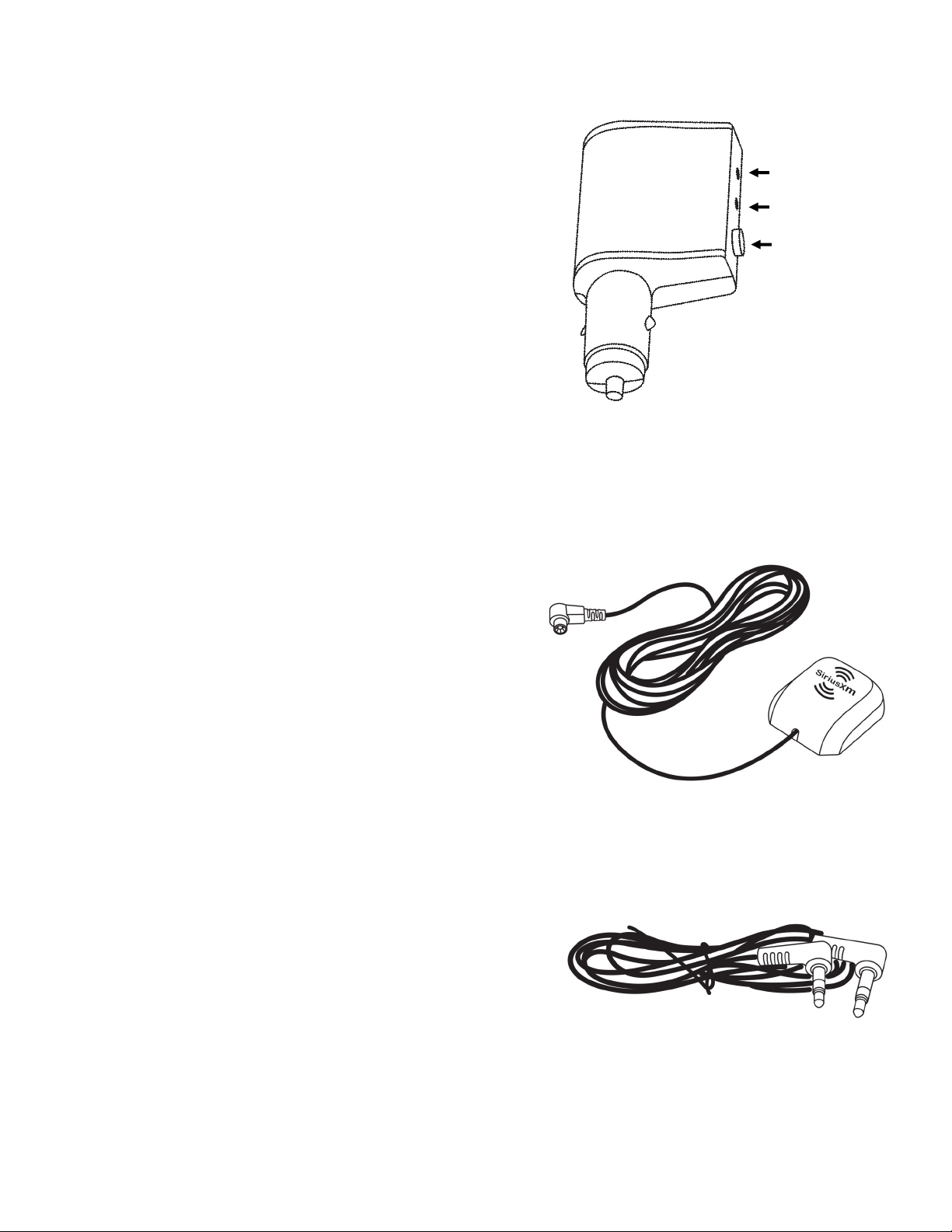
Roady BT Intelligent Power Adapter
Unlike SiriusXM Dock and Play receivers, the tuner for the
Roady BT is built into the Intelligent Power Adapter (cigaree
lighter power adapter). This means you will need to bring the
display controller and power adapter with you when moving
the unit from motorcycle to car or other locaon. The power
adapter also has all the connecons that would normally be
on a docking cradle for older Sirius, XM and SiriusXM
receivers. This means that you will need to route all cables to
the power adapter except the display controller cable. This
will be the only cable that will route to the protecve case.
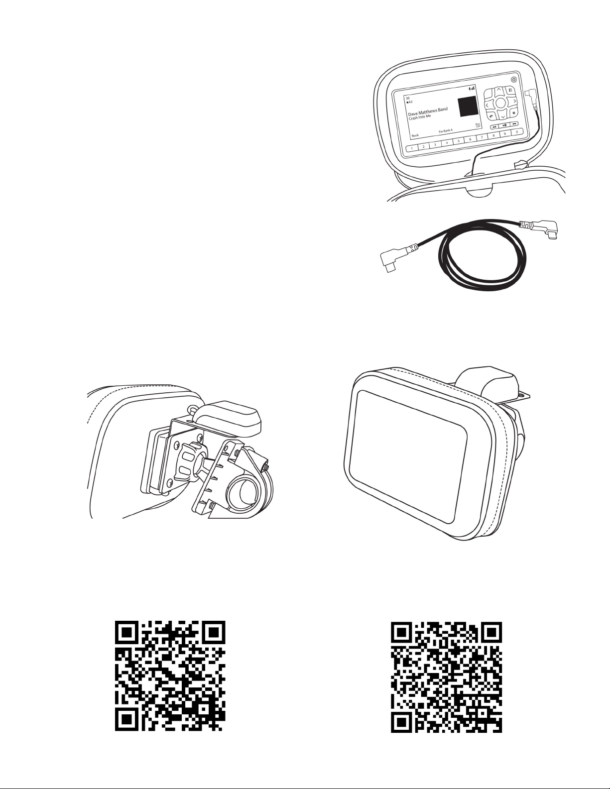
The next set of instrucons are provided as a basic reference
for installing the Roady BT with the motorcycle kit parts. Re-
fer to the Roady BT user guide for more detailed instrucons
on how to install and operate the Roady BT.
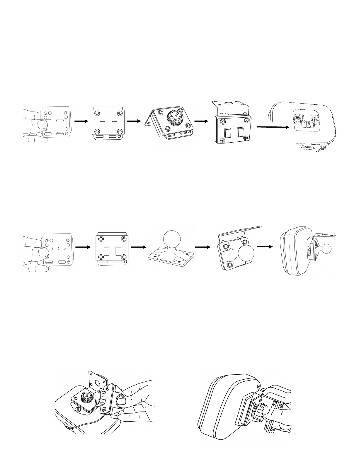
Connecng to the Intelligent Power Adapter
Step 1 - Connect Antenna Cable
In previous steps, we installed the magnec antenna to the
L-bracket. Run the antenna cable from the L-bracket to the
locaon of the power adapter and plug the antenna cable
into the antenna port on the power adapter. Be sure to leave
some slack in the line aer roung the cable from the case to
the power adapter.
Step 2 - Audio Connecon
The Roady BT has several different audio opons including
Bluetooth®, Auxiliary, FM transmission and direct FM relay
via the FMDA25. Each opon requires a different setup. Refer
to the Roady BT user guide for detailed installaon
instrucons on connecng audio. If you are connecng via
Bluetooth® or FM transmission, you will start the process
once the system is powered on. If you are connecng via AUX
or an FMDA25, you will make your connecons to the power
adapter before plugging in the adapter.
Auxiliary Audio Out
FM Audio Out
Antenna Port

Pixel Technologies, Inc. | www.pixelsatradio.com | contact[email protected]m | (800) 595-0845 | Page 4
Step 3 - Connect Display Controller
Included in the package is a micro USB to micro USB cable that
powers the display controller. Run that cable from the power
adapter to the protecve case. Feed the wire up through the
boom of the case as shown in the figure to the right. The case
has several different sized spacers. Use the spacer that best
mounts the display controller inside the case.
Note: Using all spacers will give you the best results when
pressing buons. The spacers will push the controller to the
front of the case, making it easier to press the buons on the
controller.
Addional Resources
Fully Assembled
When fully assembled, the unit should look like the images below.
Roady BT Quick Start Guide Roady BT Quick Start Guide
Table of contents
Other Pixel Motorcycle Accessories manuals