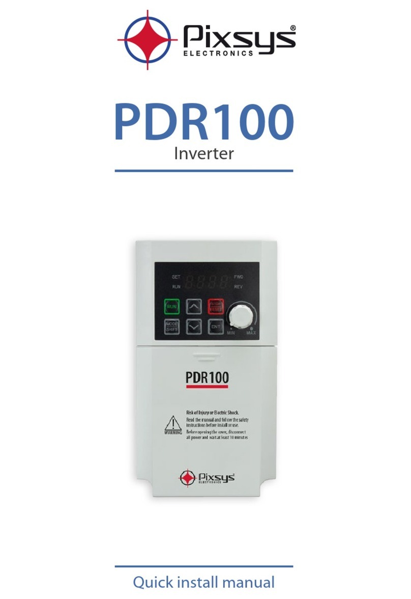
Pixsys PDR100 User manual

PDR100
Inverter
----------------------------------------------------------------------------------------------------------------------------------------
Complete manual


1
Safety Information
Safety Information
Read and follow all safety instructions in this manual precisely to avoid unsafe operating
conditions, property damage, personal injury, or death.
Safety symbols in this manual
Indicates an imminently hazardous situation which, if not avoided, will result in severe injury or
death.
Indicates a potentially hazardous situation which, if not avoided, could result in injury or death.
Indicates a potentially hazardous situation that, if not avoided, could result in minor injury or
property damage.
Safety information
•
Do not ope
n the cover of the e uipment while it is on or operating. Likewise, do not operate
the inverter while the cover is open. Exposure of high voltage terminals or charging area to
the external environment may result in an electric shock. Do not remove any cove
rs or touch
the internal circuit boards (PCBs) or electrical contacts on the product when the power is on
or during operation. Doing so may result in serious injury, death, or serious property
damage.
•
Do not open the cover of the e uipment even when the power supply to the inverter has
been turned off unless it is necessary for maintenance or regular inspection. Opening the
cover may result in an electric shock even when the power supply is off.
•
The e uipment may hold charge long after the power supply has been turned off. Use a
multi-meter to make sure that there is no voltage before working on the inverter, motor or
motor cable.

2
Safety Information
•
This e uipment must be grounded for safe and proper operation.
•
Do not supply power to a faulty inverter. If you find that the inverter is faulty, disconnect the
power supply and have the inverter professionally repaired.
•
The inverter becomes hot during operation. Avoid touching the inverter until it has cooled
to avoid burns.
•
Do not allow foreign objects, such as screws, metal chips, debris, water, or oil to get inside
the inverter. Allowing foreign objects inside the inverter may cause the inverter to
malfunction or result in a fire.
•
Do not operate the inverter with wet hands. Doing so may result in electric shock.
•
Check the protection degree of circuits and e uipments used in the inverter degree of circuit
protection and the degree of e uipment protection.
The following connection terminals and components are electrical protection class 0 devices.
The circuit is protected by the essential insulation and electric shock may occur if the
insulation is done improperly. The same protection measures for electric cables must be
taken when the using or installing the following compornents, or when you connect a cable
to the following terminals or components.
- Multi-function terminals: P1–P3, P4, P5, CM
- Analog terminal inputs and outputs: VR, V1, I2, AO, CM
- Other terminal block connectors: 24, A1, B1, C1, A2, C2
- Cooling fan
•
This inverter is a protection class 1 product.
•
Do not modify the interior workings of the inverter. Doing so will void the warranty.
•
The inverter is designed for 3-phase motor operation. Do not use the inverter to operate a single-
phase motor.
•
Do not place heavy objects on top of electric cables. Doing so may damage the cable and result in
an electric shock.

3
Quick Reference Table
The following table contains situations fre uently encountered by users while working with
inverters. Refer to the typical and practical situations in the table to uickly and easily locate
answers to your uestions.
Situation Reference
I want to configure the inverter to start operating as soon as the power source
is applied. p.90
I want to configure the motor
’
s parameters.
p.189
Something seems to be wrong with the inverter
or the motor.
p.217
What are the recommended wiring lengths? p.29
The motor is too noisy. p.134
I want to apply PID control on my system. p.125
What are the factory default settings for multi-function terminals?
p.
200
,
p. 205
I want to review recent fault trip and warning histories. p.160
I want to change the inverter’s operation fre uency using a potentiometer.
p.
73
,
p.74
p.76
I want to install a fre uency meter using an analog terminal. p.146
I want to monitor the supply current to motor.
p.
64
,
p.156
I want to operate the inverter using a multi-step speed configuration. p. 83
The motor runs too hot. p.162
The inverter is too hot. p.164
The cooling fan does not work. p.155
I want to change the items that are monitored on the keypad. p.234
I want to operate the inverter using a multi-step speed configuration. p.156

4
Table of Contents
Table of Contents
1
Preparing the Installation ...............................................................................................................
1.1
Product Identification ............................................................................................................................................ 8
1.2
Part Names ................................................................................................................................................................ 10
1.3
Installation Considerations .............................................................................................................................. 12
1.4
Selecting and Preparing a Site for Installation ...................................................................................... 13
1.5
Cable Selection ....................................................................................................................................................... 17
2
Installing the Inverter ................................................................................................................... 1
2.1
Mounting the Inverter ........................................................................................................................................ 21
2.2
Cable Wiring ............................................................................................................................................................. 24
2.3
Post-Installation Checklist ................................................................................................................................ 39
2.4
Test Run ....................................................................................................................................................................... 41
3
Default Inputs/Outputs configuration and parameters ......................................................... 43
3.1
Multi-function Inputs (PAR In).................................................................................................................. 43
3.2
Analogue input (PAR In) .............................................................................................................................. 43
3.3
Analogue output (PAR OU) ....................................................................................................................... 43
3.4
Digital/Relay and Pulse outputs (PAR OU) ........................................................................................ 44
3.5
Communication parameters (PAR CM)............................................................................................... 44
4
Learning to Perform Basic Operations ...................................................................................... 45
4.1
About the Keypad ................................................................................................................................................. 45
4.2
Learning to Use the Keypad ............................................................................................................................ 49
4.3
Actual Application Examples .......................................................................................................................... 55
4.4
Monitoring the Operation ................................................................................................................................ 64
5
Control Block Diagram.................................................................................................................. 67
5.1
Setting Fre uency ................................................................................................................................................. 68
5.2
Setting Run Command ...................................................................................................................................... 70
5.3
Controlling Acc/Dec and V/F Voltage ......................................................................................................... 71
6
Learning Basic Features ................................................................................................................ 72
6.1
Setting Fre uency Reference ......................................................................................................................... 72
6.2
Holding Analog Command Fre uency .................................................................................................... 82
6.3
Setting Multi-step Fre uency ......................................................................................................................... 83
6.4
Command Source Configuration ................................................................................................................. 85

5
Table of Contents
6.5
Forward or Reverse Run Prevention ........................................................................................................... 89
6.6
Power-on Run .......................................................................................................................................................... 89
6.7
Reset and Restart ................................................................................................................................................... 90
6.8
Setting Acceleration and Deceleration Times ....................................................................................... 91
6.9
Acc/Dec Pattern Configuration ..................................................................................................................... 96
6.10
Stopping the Acc/Dec Operation ................................................................................................................. 99
6.11
V/F (Voltage/Fre uency) Control ...............................................................................................................100
6.12
Tor ue Boost ..........................................................................................................................................................103
6.13
Stop Mode Setting..............................................................................................................................................106
6.14
Fre uency Limit ...................................................................................................................................................108
7
Learning Advanced Features ..................................................................................................... 111
7.1
DC Braking...............................................................................................................................................................111
7.2
Jog operation ........................................................................................................................................................114
7.3
Up-down Operation ..........................................................................................................................................116
7.4
3-Wire Operation .................................................................................................................................................120
7.5
Dwell Operation ...................................................................................................................................................121
7.6
Slip Compensation Operation .....................................................................................................................122
7.7
PID Control ..............................................................................................................................................................125
7.8
Energy Saving Operation ................................................................................................................................130
7.9
Speed Search Operation .................................................................................................................................131
7.10
Auto Restart Settings ........................................................................................................................................133
7.11
Operational Noise Settings (carrier fre uency settings) ...............................................................134
7.12
2nd Motor Operation ........................................................................................................................................135
7.13
Fre uency Setting and 2nd Operation Mode Setting ......................................................................136
7.14
Input Voltage Setting ........................................................................................................................................139
7.15
Parameter Initialization ....................................................................................................................................140
7.16
Parameter Lock .....................................................................................................................................................142
7.17
Voltage Trip Prevention During Deceleration .....................................................................................143
7.18
Brake Control .........................................................................................................................................................144
7.19
Analog Output ......................................................................................................................................................146
7.20
Digital Output .......................................................................................................................................................147
7.21
Draw Operation ....................................................................................................................................................153
7.22
Operation Mode Setting When Cooling Fan is Abnormal ...........................................................155

6
Table of Contents
7.23
Operation State Monitor .................................................................................................................................156
7.24
I/O Terminal Block State Monitor ................................................................................................................159
7.25
Fault State Monitor .............................................................................................................................................160
Learning Protection Features .................................................................................................... 162
8.1
Motor Protection .................................................................................................................................................162
8.2
Inverter and Se uence Protection .............................................................................................................166
9
RS-4 5 Communication Features ............................................................................................. 174
9.1
Communication Standards ...........................................................................................................................174
9.2
Communication System Configuration..................................................................................................175
9.3
Communication Protocol ...............................................................................................................................179
9.4
Compatible Common Area Parameter ...................................................................................................183
10
Table of Functions........................................................................................................................ 1 7
10.1
Operation Group .................................................................................................................................................187
10.2
Drive Group (PAR → dr) ...................................................................................................................................189
10.3
Basic Function group (PAR→bA) ................................................................................................................191
10.4
Expanded Function group (PAR→Ad) ....................................................................................................196
10.5
Control Function group (PAR→Cn) ...........................................................................................................199
10.6
Input Terminal Block Function group (PAR→In) ................................................................................200
10.7
Output Terminal Block Function group (PAR→OU) ........................................................................205
10.8
Communication Function group (PAR→CM) .....................................................................................208
10.9
Application Function group (PAR→AP) .................................................................................................210
10.10
Protection Function group (PAR→Pr) ......................................................................................................212
10.11
2nd Motor Function group (PAR→M2) ..................................................................................................216
10.12
Config Mode group (PAR→CF) ...................................................................................................................217
11
Troubleshooting .......................................................................................................................... 219
11.1
Trips .............................................................................................................................................................................219
11.2
Troubleshooting Fault Trips ...........................................................................................................................222
11.3
Troubleshooting Other Faults ......................................................................................................................224
12
Maintenance ................................................................................................................................. 230
12.1
Regular Inspection Lists ...................................................................................................................................230
12.2
Storage and Disposal ........................................................................................................................................234
13
Technical Specification ............................................................................................................... 235
13.1
Input and Output Specification ..................................................................................................................235

7
Table of Contents
13.2
Product Specification Details ........................................................................................................................236
13.3
External Dimensions (IP 20 Type) ...............................................................................................................238
13.4
Peripheral Devices ..............................................................................................................................................240
13.5
Fuse and Reactor Specifications .................................................................................................................240
13.6
Terminal Screw Specification ........................................................................................................................241
13.7
Braking Resistor Specification ......................................................................................................................241
13.8
Continuous Rated Current Derating.........................................................................................................242
13.9
Remote Keypad Option ...................................................................................................................................244

8
Preparing the
Installation
Preparation
1Preparing the Installation
This chapter provides details on product identification, part names, correct installation and cable
specifications. To install the inverter correctly and safely, carefully read and follow the instructions.
1.1 Product Identification
The PDR100 Inverter is manufactured in a range of product groups based on drive capacity and
power source specifications. Product name and specifications are detailed on the rating plate. The
illustration on the next page shows the location of the rating plate. Check the rating plate before
installing the product and make sure that the product meets your re uirements. For more
detailed product specifications, refer to 13.1 Input and Output Specification on page 235.
Note
Check the product name, open the packaging,
and then confirm that the product
is free from
defects. Contact your supplier if you have any issues or uestions about your product.
PDR100 Code composition
The tabel below describes PDR100 codes composition accordingly to the inverter’s capacity.
Series name – N° phases – Capacity – Input voltage
Series name
N° phases
Capacity
Input voltage
PDR100 1PH
0040 (0.4kW)
2 (200-240V) 0075 (0.75kW)
0220 (2.2kW)
Example:
PDR100 - 1PH - 0220 - 2
Identify a PDR100 V/F inverter with single phases 200-240V input and 2.2kW power capacity.

9
Preparing the
Installation
Preparation
PDR100 Models list
The tabel below describes PDR100 models name with main characteristics for ordering.
Model
Main characteristics
PDR100-1PH-0040-2
1x200-240VAC, 0.4kW - 2.4A HD FB, IP20, EMC FILTER C2, LED KEYPAD, MODBUS RTU
PDR100-1PH-0075-2
1x200-240VAC, 0.75kW - 4.2A HD FB, IP20, EMC FILTER C2, LED KEYPAD, MODBUS RTU
PDR100-1PH-0220-2
1x200-240VAC, 2.2kW - 10A HD FB, IP20, EMC FILTER C2, LED KEYPAD, MODBUS RTU

10
Preparing the
Installation
Preparation
1.2 Part Names
The illustration below displays part names. Details may vary between product groups.
0.4~0.75 kW (Single Phase)

11
Preparing the
Installation
Preparation
2.2 kW (Single Phase)

12
Preparing the
Installation
Preparation
1.3 Installation Considerations
Inverters are composed of various precision, electronic devices, and therefore the installation
environment can significantly impact the lifespan and reliability of the product. The table below
details the ideal operation and installation conditions for the inverter.
Items
Description
Ambient Temperature
1)
14–122°F (-10–50
℃
)
Ambient Humidity
95% relative humidity (no condensation)
Storage Temperature - 4–149°F (-20–65
℃
)
Environmental Factors
An environment free from corrosive or flammable gases, oil residue or
dust
Altitude/Vibration
Lower than 3,280 ft (1,000 m) above sea level/less than 1G (9.8 m/
sec
2
)
Air Pressure
70~106 kPa
1) The ambient temperature is the temperature measured at a point 2” (5 cm) from the surface of the inverter.
Do not allow the ambient temperature to exceed t
he allowable range while operating the
inverter.

13
Preparing the
Installation
Preparation
1.4 Selecting and Preparing a Site for Installation
When selecting an installation location consider the following points:
•
The inverter must be installed on a wall that can support the inverter’s weight.
•
The location must be free from vibration. Vibration can adversely affect the operation of the
inverter.
•
The inverter can become very hot during operation. Install the inverter on a surface that is fire-
resistant or flame-retardant and with sufficient clearance around the inverter to allow air to
circulate. The illustrations below detail the re uired installation clearances.

14
Preparing the
Installation
Preparation
•
Ensure sufficient air circulation is provided around the inverter when it is installed. If the
inverter is to be installed inside a panel, enclosure, or cabinet rack, carefully consider the
position of the inverter’s cooling fan and the ventilation louver. The cooling fan must be
positioned to efficiently transfer the heat generated by the operation of the inverter.

15
Preparing the
Installation
Preparation
•
If you are installing multiple inverters in one location, arrange them side by side and remove
their top covers (optional). The top covers MUST be removed for side-by-side installations. Use
a flat head screwdriver to remove the top covers.
•
Keep the distance between inverters at least 0.1’’.

16
Preparing the
Installation
Preparation
•
If you are installing multiple inverters, of different ratings, provide sufficient clearance to meet
the clearance specifications of the larger inverter.

17
Preparing the
Installation
Preparation
1.5 Cable Selection
When you install power and signal cables in the terminal blocks, only use cables that meet the
re uired specification for the safe and reliable operation of the product. Refer to the following
information to assist you with cable selection.
•
Wherever possible use cables with the largest cross-sectional area for mains power wiring, to
ensure that voltage drop does not exceed 2%.
•
Use copper cables rated for 600V, 75
℃
for power terminal wiring.
•
Use copper cables rated for 300V, 75
℃
for control terminal wiring.
Ground Cable and Power Cable Specifications
Load (kW)
Ground
Power I/O
mm
2
AWG
mm
2
AWG
R/S/T
U/V/W
R/S/T
U/V/W
Single Phase
200V
0.4 3.5 12 2 2 14 14
0.75
2.2 3.5 12 3.5 3.5 12 12
Signal (Control) Cable Specifications
Terminal
Signal Cable
Without Crimp Terminal Connec
tors
(Bare wire)
With Crimp Terminal Connectors
(Bootlace Ferrule)
mm
2
AWG
mm
2
AWG
P1~P5/CM/VR/V1/I2/
AO/24 0.75 18 0.5 20
A1/B1/C1/A2/C2
1.0
17
1.5
15
For more details, refer to 2.2 Cable Wi ing Step 4 Cont ol Te minal Wi ing on page 30.

18
Installation
Installing the Inverter
2Installing the Inverter
This chapter describes the physical and electrical installation methods, including mounting and
wiring of the product. Refer to the flowchart and basic configuration diagram provided below to
understand the procedures and installation methods to be followed to install the product
correctly.
Installation Flowchart
The flowchart lists the se uence to be followed during installation. The steps cover e uipment
installation and testing of the product. More information on each step is referenced in the steps.
Product Identification (1.1 Product Identification)
Select the Installation Location (1.3 Installation Considerations)
Mounting the Inverter (2.1 Mounting the Inverter )
Wiring the Ground Connection (2.2 Cable Wiring)
Power and Signal Wiring (2.2 Cable Wiring)
Post-Installation Checks
Turning on the Inverter
Parameter Configuration (4.2 Learning to Use the Keypad)
Testing
Other manuals for PDR100
1
Table of contents
Other Pixsys Inverter manuals
Popular Inverter manuals by other brands

Siemens
Siemens SINAMICS G120P instruction manual

Hobart
Hobart 60CU24 Operation and maintenance manual with illustrated parts list

Zeus Appollo
Zeus Appollo Z20I1K user manual

Kaco
Kaco blueplanet 3.0 NX3 M2 manual

Mitsubishi Electric
Mitsubishi Electric FR-A8AX instruction manual

AEG
AEG AS-IR02 Series Configuration guide