PKP DG04 Series User manual

Instruction Manual
DG04
Flow Sight Class
for Installation between two Flanges
PKP Prozessmesstechnik GmbH
Borsigstraße 24
D-65205 Wiesbaden- ordenstadt
Tel.: ++49-(0)6122-7055-0
Fax: ++49-(0)6122-7055-50
Email: info@pkp.de – www.pkp.de

Table of Contents
Safety Information..................................................................................................................2
Mounting instructions.............................................................................................................3
Maintenance and care...........................................................................................................4
Safety Information
General Instructions
To ensure safe operation, the device should only be operated according to the specifica -
tions in the instruction manual. The requisite Health & Safety regulations for a given
application must also be observed. This statement also applies to the use of accessories.
Every person who is commissioned with the initiation or operation of this device must have
read and understood the operating instructions and in particular the safety instructions!
The liability of the manufacturer expires in the event of damage due to improper use, non-
observance of this operating manual, use of insufficiently qualified personnel and unau-
thorized modification of the device.
Proper sage
The sight class of the DG04 series are used for the optical control monitoring of liquids.
Any other use of the device is prohibited and outside the scope of application.
In particular, applications in which shock loads occur (for example, pulsed operation)
should be discussed and checked in advance with our technical staff.
The devices of the DG04 series should not be used as sole monitoring devices in order to
detect or even avoid dangerous operating states in plants and machines. The plant or
machine itself must be planned and constructed in such a way that critical conditions
which pose a danger to man and the environment are excluded from the outset
Dangerous substances
For dangerous media such as e.g. Oxygen, Acetylene, flammable or toxic substances as
well as refrigeration systems, compressors, etc. must comply with the relevant regulations
beyond the general rules.
Qualified Personnel
The devices of the DG04 may only be installed by trained, qualified personnel who are
able to mount the devices correctly. Qualified personnel are persons, who are familiar with
assembling, installation, placing in service and operating these devices and who are suit-
ably trained and qualified.
DG04 Instruction manual 12/2020 page 2

Inward Monitoring
Please check directly after delivery the device for any transport damages and deficiencies.
Additional with reference to the accompanying delivery note the number of parts must be
checked.
Claims for replacement or goods which relate to transport damage can only be considered
valid if the delivery company is notified without delay.
Mounting instructions
General information:
•Only carry out installation and maintenance work when the unit is depressurised
and has cooled down.
•The installation position is horizontal or vertical with flow from bottom to top.
•Piping, tank and sightglass frame must be free from contamination.
•The assembly must be stabil without the sightglass frame, as this must not be used
to stabilise the piping
•It is essential to protect the sealing surfaces of the base flange from damage (e.g.
during welding work).
Flanges:
•Piping flanges must be plane-parallel and concentric
•Flange size and design of the sealing surface must match the flow sight glass
•Distance of the pipe flanges: Overall length of the flow sight glass + double the
gasket thickness.
•The connecting screws must be tightened crosswise, gradually and evenly.
•Torques depend primarily on the gasket material used.
Seals:
•Place the new gasket and the sight glass exactly centrically on the lower gasket.
•The inscription on the gasket must face outwards.
•The gasket must not protrude into the inner diameter D .
•Contact between the sight glass and the flange is not permissible, as this can
damage the sight glass due to different expansion coefficients.
•Place the upper gasket and the cover flange exactly centrically on the glass tube.
DG04 Instruction manual 12/2020 page 3

Tighten the screws:
•Tighten the screws in many small steps crosswise using a torque spanner to the
tightening torques of the screw/sealant combination.
•To avoid glass distortion, all screws must have exactly the same tightening torque.
•We recommend lubricated screws. For the recommended torques of the cover
screws and the standard seals, please refer to the respective product data sheets
of the corresponding manufacturers.
After commissioning:
•Under the influence of pressure and temperature, you can expect the seal to "set".
•Check the torques of the fastening screws again in a cold and depressurised state
and correct if necessary.
Maintenance and care
The sight glasses are insensitive to contamination, as the inner surface is flushed by the
flowing medium.
The sight glasses have no dead spaces, so that the sight glass can be flushed or cleaned
together with the pipeline when changing the product.
The sight glasses are insensitive to contamination because the inner surface is rinsed by
the flowing medium.
The sight glasses have no dead spaces, so that when the product is changed, the sight
glass can be rinsed or cleaned together with the piping.
When cleaning the outer glass surface, use a clean and soft cloth and avoid scratching
the glass (loss of strength). Commercially available cleaning agents (e.g. glass cleaner)
may be used.
If the glass is also so dirty from the inside that it cannot be rinsed free by the medium
itself, the sight glass can be removed and cleaned in the same way as from the outside
(loosen the fastening nuts crosswise).
When reinstalling, always use new gaskets.
If the surface of the sight glass is affected (scratches, fissured surface, visible glass
erosion due to milky surface), the sight glass must be replaced, as a loss of strength must
be assumed.
DG04 Instruction manual 12/2020 page 4

Flow Measurement and Monitoring
DG04
Flow Sight Glass for
Installation between Two Flanges
•for liquids and gases
•360° all round isibility
•easy installation between two DIN-
or ANSI-flanges
•DN 10 up to DN 250
•design in acrylic, borosilicate or quartz glass
•insensiti e to contamination
•maximum pressure 16 bar
•max. temperature: 1100 °C
Description:
Model series DG04 sight glasses are distinguished by their
rugged construction and wide range of applications. A 50 mm
long ring made of acrylic, borosilicate or quart glass with very
thick walls is clamped between two existing flanges. Their
dimensions match those of the sealing face on the raised area
of the flange. This si ing makes support from a separate
metal housing unnecessary.
In addition, this design allows the flow to be viewed and
monitored from any direction. The flange screws provide
additional protection against mechanical damage.
The sight glass has no dead spaces, so that it can be
flushed / cleaned together with the pipeline when changing
products.
There are no deposits in the sight glass when the pipeline is
drained, because the inner diameter of the sight glass corre-
sponds to the inner diameter of the pipeline. The DG04 are
therefore also ideally suited for sterile and antiseptide applica-
tions.
Typical applications:
In the borosilicate glass version, the units can be used for
chemically very aggressive media. The quart glass version
can be used for very high media temperatures of up to
1100 °C. They are insensitive to contamination because the
inner surface is always rinsed by the flowing medium.
In particular, the larger nominal si es are very cost effective
solutions since they only require the transparent cylinder and
no metal housing with flanges.
PKP Prozessmesstechnik GmbH
Borsigstr. 24 • D-65205 Wiesbaden
S +49 (0) 6122-7055-0 • T +49 (0) 6122 7055-50
[email protected] • www.pkp.de
20210318
Flange not included in
scope of delivery

Models:
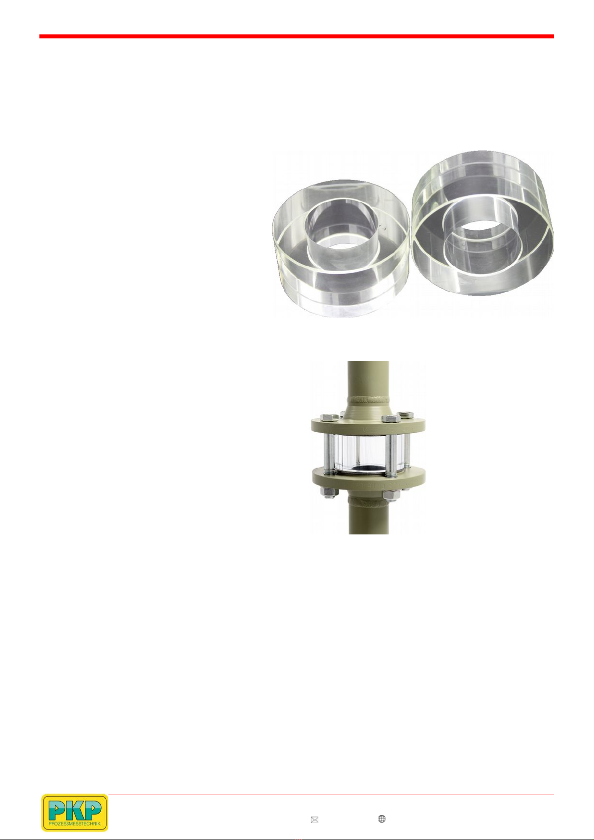
DG 04.A: material: acrylic glass
max. temperature: +80 °C
DG 04.B: material: borosilicate glass
max. temperature: -200...+300 °C
for aggressive medias and high temperatures
DG 04.Q: material: quart glass-
max. temperature: +1100 °C
max. pressure: on request
for aggressive medias and very high temperatures
Dimensions:
Dimensions, Pressure Stage, Weight:
ight glasses for flanges acc. to DIN 1092-1:
Pressure tage / Weight [kg]
Nomi-
nal
size
Ø
Inner
Di
[mm]
Ø
Outer
[mm]
Acrylic Borosilicate
DN 10 14 40 PN 16 / 0,07 PN 16 / 0,13
DN 15 18 45 PN 16 / 0.008 PN 16 / 0,16
DN 20 22 58 PN 16 / 0,14 PN 16 / 0,27
DN 25 29 68 PN 16 / 0,18 PN 16 / 0,36
DN 32 38 79 PN 16 / 0,23 PN 16 / 0,46
DN 40 44 88 PN 16 / 0,28 PN 16 / 0,56
DN 50 55 102 PN 16 / 0,36 PN 16 / 0,71
DN 65 71 122 PN 16 / 0,47 PN 16 / 0,94
DN 80 83 138 PN 10 / 0,59 PN 16 / 1,16
DN 100 108 158 PN 10 / 0,64 PN 16 / 1,27
DN 125 132 188 PN 10 / 0,86 PN 16 / 1,71
DN 150 160 212 PN 10 / 0,93 PN 16 / 1,85
DN 200 208 268 PN 10 / 1,38 PN 16 / 2,73
DN 250 260 320 PN 8 / 1,65 PN 10 / 3,28
DN 300 310 370 PN 6 PN 10
Standard length BL = 50 mm
Larger si es, pressures and other lengths on request.
The pressure-temperature limits according to
DIN EN 1092-1
Order Code:
Order number: DG04.
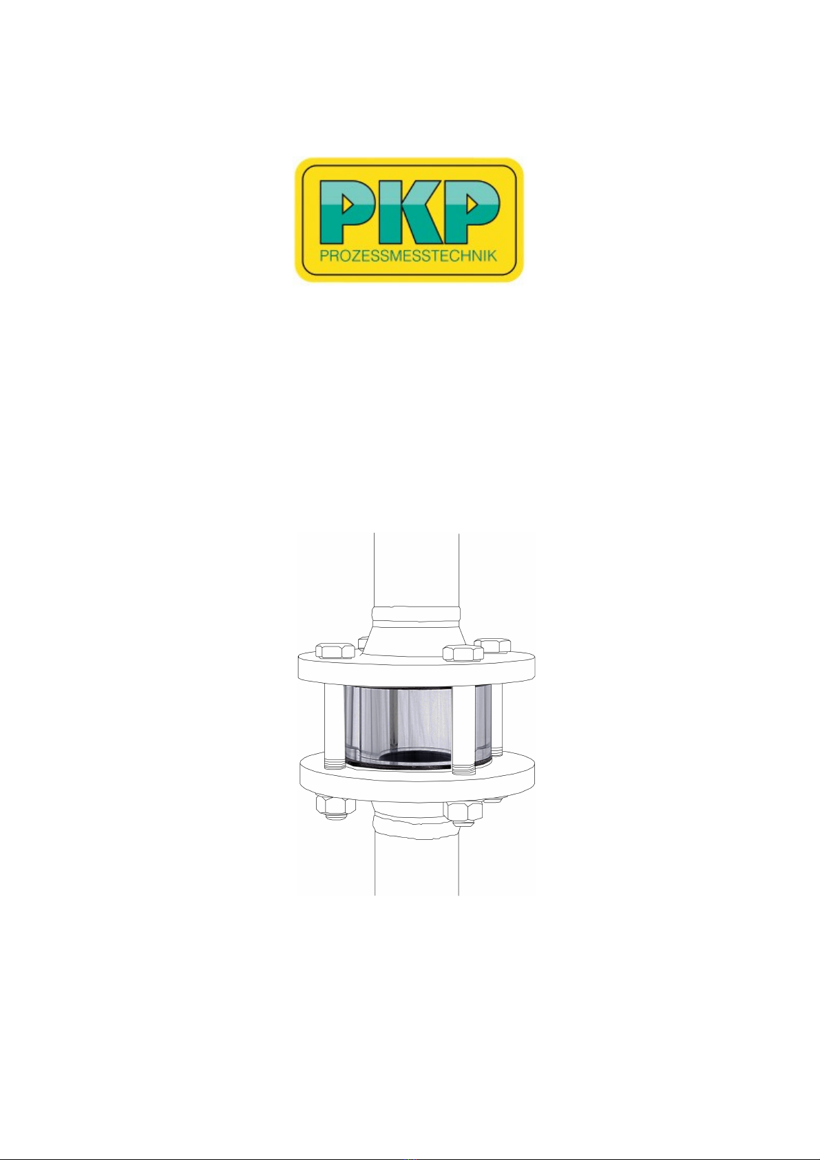
Flow sight glass for installation
between two flanges
A. 50. D. 025. 0
Models:
A = acrylic glass
B = borosilicate glass
Q = quart glass
Length:
050 = 50 mm (standard)
030 = 30 mm
100 = 100 mm
Special length on request
Connection:
D = flange acc. to DIN 1092-1, max. PN 16
A = ASMEI-flange 16.5 B, max. PN 20
Nominal size:
010...300 = nominal si e appropriate table „Dimensions“
Options:
0 = without
1 = please specify in plain text
Advice:
The flanges, screws and gaskets are not included in the delivery.
ight glasses for A ME flanges acc. to 16.5 B, Class 150:
Pressure tage / Weight [kg]
NP Ø
Inner
Di
[mm]
Ø
Outer
[mm]
Acrylic Borosilicate
3/8“ / / / /
1/2“ 16 35 PN 19 / 0,05 PN 20 / 0,09
3/4“ 21 43 PN 18 / 0,07 PN 20 / 0,13
1“ 27 50 PN 16 / 0,09 PN 20 / 0,17
1 1/4“ 35 63 PN 16 / 0,13 PN 20 / 0,26
1 1/2“ 41 73 PN 16 / 0,18 PN 20 / 0,35
2“ 53 92 PN 16 / 0,27 PN 20 / 0,54
2 1/2“ 63 105 PN 14 / 0,34 PN 20 / 0,67
3“ 78 127 PN 14 / 0,48 PN 20 / 1,96
4“ 102 157 PN 10 / 0,69 PN 20 / 1,36
5“ 128 186 PN 10 / 0,88 PN 19 / 1,74
6“ 154 216 PN 8 / 1,11 PN 16 / 2,19
8“ 203 270 PN 8 / 1,53 PN 15 / 3,03
10“ 255 324 PN 6 / 1,93 PN 10 / 3,82
12“ 305 381 PN 6 PN 10
Standard length BL = 50 mm
Larger si es, pressures and other lengths on request.
The pressure-temperature limits according to ASME 16.5 B!
PKP Prozessmesstechnik GmbH
Borsigstr. 24 • D-65205 Wiesbaden
S +49 (0) 6122-7055-0 • T +49 (0) 6122 7055-50
[email protected] • www.pkp.de
Flow
This manual suits for next models
3
Table of contents
Other PKP Industrial Equipment manuals
Popular Industrial Equipment manuals by other brands

KAKA Industrial
KAKA Industrial W-2416Z Operation manual

SEW-Eurodrive
SEW-Eurodrive SPIROPLAN W R 7 Series Assembly and operating instructions

Halfen
Halfen HLB Series Assembly instructions

Innotech
Innotech QUADRAT-13 Instructions for installation and use

MITARI
MITARI MPLF operating instructions

Trotec
Trotec DH 25 S Original instructions