Planar EL160.120.39 User manual

EL160.120.39
EL Small Graphics Display
USER’S MANUAL
www.planar.com

Revision Control
Date Description
July 1999 Document number OM120-00
June 2004 Document number 020-0344-00A

Contents
EL160.120.39 Display................................................................................................................................................2
Features ...................................................................................................................................................................2
Installation and Handling........................................................................................................................................3
Mounting EL Displays..........................................................................................................................................3
Cable Length...........................................................................................................................................................3
Cleaning ...................................................................................................................................................................4
Avoiding Burn-In ...................................................................................................................................................4
Specifications ..............................................................................................................................................................4
Power.........................................................................................................................................................................4
Data and Power Connector...............................................................................................................................5
Generating Grayscales.........................................................................................................................................6
Interface Information...........................................................................................................................................6
Video Input Signals..........................................................................................................................................
6
Self-Test Mode........................................................................................................................................................7
Optical.......................................................................................................................................................................8
Dimming ..................................................................................................................................................................8
Environmental........................................................................................................................................................9
Reliability..................................................................................................................................................................9
Safety and EMI Performance.............................................................................................................................9
Mechanical Characteristics..............................................................................................................................10
Component Envelope .......................................................................................................................................10
Description of Warranty ........................................................................................................................................12
Ordering Information.............................................................................................................................................12
Support and Service................................................................................................................................................12
Figures
Figure 1. Data/Power Connector.....................................................................................................................5
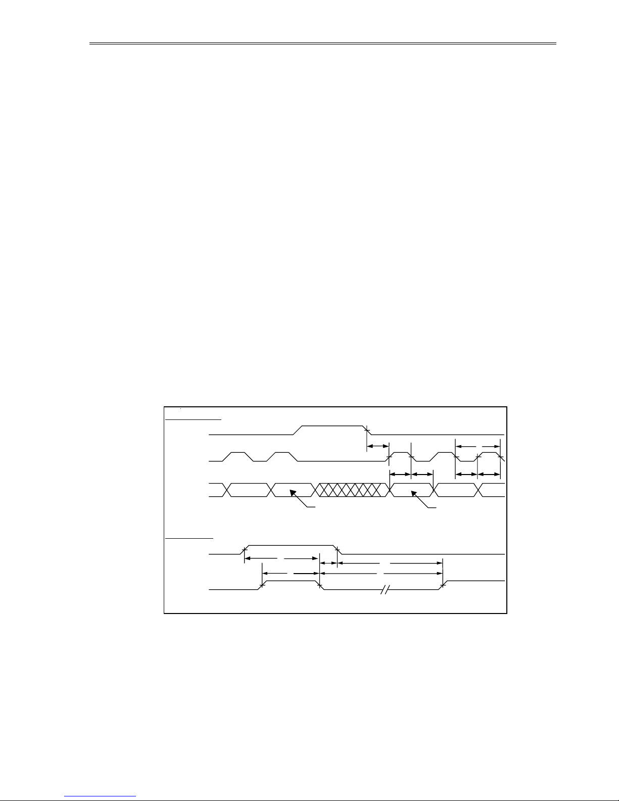
Figure 2. Video Input Timing Diagram..........................................................................................................6
Figure 3. Pixel Location versus Sequence of Data.....................................................................................7
Figure 4. Display Dimensions..........................................................................................................................11
Tables
Table 1. DC Input Voltage Requirements. ....................................................................................................4
Table 2. Video Input Requirements. ...............................................................................................................5
Table 3. Connector Pinouts. ..............................................................................................................................5
Table 4. Video Input Descriptions. ..................................................................................................................7
Table 5. Optical Characteristics........................................................................................................................8
Table 6. Dimming Rates......................................................................................................................................8
Table 7. Environmental Characteristics.........................................................................................................9
Table 8. Mechanical Characteristics..............................................................................................................10

EL160.120.39 Operations Manual (020-0344-00A)
2
EL160.120.39 Display
The EL160.120.39 thin film electroluminescent (EL) display is a high
visual performance small graphic display that excels in a wide range of
ambient lighting environments. The EL160.120.39 utilizes Planar’s
proprietary Integral Contrast Enhancement (ICE
™
) technology to
achieve unparalleled image quality without the use of filters or
temperature compensation.
The display module consists of an EL glass panel and control
electronics assembled into a space-saving, rugged package for easy
mounting and includes an integrated DC/DC converter. The
EL160.120.39 is easily interfaced using standard 4-bit LCD control
signals. Each of the pixels has an aspect ratio of 1:1 and is individually
addressable to clearly display high information-content graphics and
text.
Features and Benefits
• Excellent visual performance:
High brightness and contrast
Wide viewing angle >160°
• Rapid display response <1 ms
• Space efficient mechanical package
• Low EMI emissions
• Extremely rugged and durable
• Reliable, long operating life: >50,000 MTBF
• 4-bit LCD-type interface

EL160.120.39 Operations Manual (020-0344-00A) 3
Installation and Handling
Do not drop, bend, or flex the display. Do not allow objects to strike the
surface of the display.
CAUTION: The display uses CMOS and power MOS-FET devices. These
components are electrostatic sensitive. Unpack, assemble, and examine this
assembly in a static-controlled area only. When shipping, use packing
materials designed for protection of electrostatic-sensitive components.
CAUTION: To prevent injury in the event of glass breakage, a protective
overlay should be used on the viewer side of the display.
Mounting
Properly mounted, EL displays can withstand high shock loads as well as
severe vibration found in demanding applications. However the glass panel
used in an EL display will break if subjected to bending stresses, high impact,
or excessive loads.
Avoid bending the display. Stresses are often introduced when a display is
mounted into a product. Ideally, the mounting tabs of the display should be
the only point of contact with the system. Use a spacer or boss for support;
failure to do so will bend the display and cause the glass to break. The
instrument enclosure or frame should not flex or distort in such a way that
during use the bending loads might be transferred to the display. Mounting
surfaces should be flat to within ±0.6 mm (±.025"). Use all the mounting holes
provided. Failure to do so will impair the shock and vibration resistance of the
final installation.
The EL160.120.39 is a tab mounted display. Use appropriate length standoffs
to assure that screws through the mounting tabs do not introduce bending
stresses into the display. Do not deflect the circuit board out of its normal
plane.
WARNING: These products generate voltages capable of causing personal
injury (high voltage up to 230 V
ac
). Do not touch the display electronics
during operation.
Cable Length
A maximum cable length of 600 mm (24 in.) is recommended. Longer cables
may cause data transfer problems between the data transmitted and the
display input connector. Excessive cable lengths can pick up and source
unwanted EMI. There are techniques which allow this maximum cable length
to be exceeded. Contact Planar Application Engineering for more information.

EL160.120.39 Operations Manual (020-0344-00A)
4
Cleaning
As with any glass or coated surface, care should be taken to minimize
scratching. Clean the display glass with mild, water-based detergents only.
Apply the cleaner sparingly to a soft cloth, then wipe the display. Disposable
cleaning cloths are recommended to minimize the risk of inadvertently
scratching the display with particles embedded in a re-used cloth. Particular
care should be taken when cleaning displays with anti-glare or anti-reflective
films.
Avoiding Burn-In
As with other light emitting displays, displaying fixed patterns on the screen
can cause burn-in, where luminance variations can be noticed. Use a screen
saver or image-inversion technique to avoid causing burn-in on the display.
Specifications
The EL panel is a matrix structure with column and row electrodes arranged in
an X-Y formation. Light is emitted when an AC voltage of sufficient amplitude
is applied at a row-column intersection. The display operation is based on the
symmetric, line-at-a-time data addressing scheme. Performance characteristics
are guaranteed when measured at 25°C with rated input voltage unless
otherwise specified.
Power
The supply voltages are shown in Table 1. All internal high voltages are
generated from the display supply voltage (VH). The logic supply voltage (VL)
should be present whenever video input signals or VH is applied. The
minimum and maximum specifications in this manual should be met, without
exception, to ensure the long-term reliability of the display. Planar does not
recommend operation of the display outside these specifications.
Any combination or sequencing in the application or removal of VL, VH, or
video signals will not result in abnormal display operation or display
catastrophic failure.
Table 1. DC Input Voltage Requirements.
Description Symbol Min Typ Max Absolute Max Units
Input voltage (nom=12.0V) V
H
8 18 19 Vdc
Input voltage (nom=5.0V) V
L
4.75 5.25 6.0 Vdc
12V Input current (V
H
=12.0V) I
H
max 0.35 Adc
5V Input current (V
L
=5.0V) I
L
max 0.10 Adc
Power consumption 5 V/12 V
@ max. frame rate
3.0 3.9 W
CAUTION: Absolute maximum ratings are those values beyond which
damage to the device may occur.

EL160.120.39 Operations Manual (020-0344-00A) 5
Table 2. Video Input Requirements.
Description Min Max Units Notes
Absolute Input Voltage Range -0.5 V
H
+ 0.5 V V VImax
Video logic high voltage 70% 100% V VI
H
Video logic low voltage 0% 20% V VI
L
Video logic input current -10 +10 µA II
L
All data signal inputs are LC-filtered (lowpass, -3db at ca 13 MHz) CMOS. See
information about current-limiting circuit for safety on page 9.
Data and Power Connector
The EL160.120.39 uses the 20-pin, 2-mm locking connector, Samtec
EHT-110-01-S-D. The mating connector is the Samtec TCSD family of cable
strips. Compatibility with non-Samtec equivalents should be verified before
use.
Figure 1. Data/Power
Connector.
Table 3. J1 Connector Pinouts.
Pin Signal Description Pin Signal Description
1 V
H
+12 V Power 2 V
H
+12 V Power
3 Selftest Selftest Input
1
4 LUM Luminance Control
5 V
L
+5 V Power 6 GND Ground
7 VS Vertical Sync 8 GND Ground
9 HS Horizontal Sync 10 GND Ground
11 VCLK Video Clock 12 GND Ground
13 VID
0
Video Data 14 GND Ground
15 VID
1
Video Data 16 GND Ground
17 VID
2
Video Data 18 GND Ground
19 VID
3
Video Data 20 GND Ground
1
Connect pin 3 to ground for normal display operation.
Pin 1
Key
(Viewed from electronics side of display)
(Viewed from top of connector)
Pin 1
Pin 2
Key

EL160.120.39 Operations Manual (020-0344-00A)
6
Generating Grayscales
The EL160.120.39 is a monochrome display but will display dithered grayscale
when driven by a suitably-equipped video controller. See Application Note
119 for more information.
Interface Information
Planar EL Small Graphics Displays (SGD) incorporate an interface that is similar
to many LCD modules. This interface is supported by a variety of off-the-shelf
chip sets which take care of all display control functionality, freeing the system
processor for other tasks. This 4-bit LCD-type video interface provides a low
cost, flexible method for controlling display brightness and power
consumption.
Video Input Signals
The end of the top line of a frame is marked by VS, vertical sync signal as
shown in Figure 2. The first pixel of each row is marked by the falling edge of
HS. The first 160 pixels, or 40 clocks, after the falling edge of HS will be visible
on the display.
The VS signal is active high. It may be independently set to a CMOS low level at
any time for longer than one frame period. During the time of VS inactivity the
display is blank. Halting VS results in a standby condition to minimize power
consumption. Input signals VID3 through VID0 contain the video data for the
screen. Pixel information is supplied from left to right and from top to bottom
four pixels at a time.
HS
VCLK
VID3-0
VS
HS
3
First Line VID Data
4
1
Pixels: w x y z
Horizontal Timing
Vertical Timing
Pixels: a b c d
5
6
910
7
11
8
2
Second Line VID Data
Figure 2. Video Input Timing Diagram.
Timing is compatible with LCD graphics controllers such as the SED 1335.

EL160.120.39 Operations Manual (020-0344-00A) 7
Table 4. Video Input Descriptions.
Num Description Symbol Min. Typ. Max. Units
1 HS high time tHSh 100 nsec
2 HS low time tHSl 40 tVCLK
3 HS to VCLK rise tHSsu 95 nsec
4 VID setup to VCLK tVIDsu 50 nsec
5 VID hold from VCLK tVIDhd 50 nsec
6 VID clock period tVCLK 140 nsec
VCLK rise, fall time tVCLKrf 10 15 nsec
7 VCLK low width tVCLKl 60 nsec
8 VCLK high width tVCLKh 60 nsec
9 VS high setup to HS low tVShsu 140 nsec
10 VS hold after HS tVShd 140 nsec
11 VS low setup to HS high tVSlsu 140 nsec
12 HS period tHS 52 µsec
VS period tVS 121 tHS
Frame Rate fVS 0 150 Hz
a b c d e f g h i j k l m n o p
EL Panel
(Front)
w xyz
a
b
c
d
e
f
g
h
i
j
k
l
m
n
o
p
w
x
y
z
VID3
VID2
VID1
VID0
Row 1
Figure 3. Pixel Location versus Sequence of Data.
Self-Test Mode
The display incorporates a self-test mode composed of two patterns displayed
for approximately one minute each, and then repeated. The patterns are as
follows: Full On and 1 x 1 Checkerboard. The self-test mode is entered at
power on until two VS signals are detected or when pin 3 is pulled high. For
normal operation the SELFTEST pin must be connected to GROUND.

EL160.120.39 Operations Manual (020-0344-00A)
8
Optical
Table 5. Optical Characteristics.
Luminance
L
on
(areal), min
L
on
(areal), typ
L
off
(areal), max
50 cd/m²
70 cd/m²
0.3 cd/m²
screen center, 150 Hz frame rate
5 points: center plus four corners measured 10±
2 mm from display edges, 150 Hz
Non-uniformity
All pixels fully lit 25% Maximum difference between two of five points,
using the formula:
LNU%=[1- (min_lum/max_lum)] x 100
Luminance Variation (Temperature)
Maximum ±20% Across operating temperature range @120 Hz
Luminance Variation (Time)
Maximum <20%
10,000 hours at 25°C ambient @ 120 Hz
Viewing Angle
Minimum >160°
Contrast Ratio
Typical 59:1
32:1
4.3:1
@ 500 lux ambient, max frame rate
@ 1,000 lux ambient, max frame rate
@ 10,000 lux ambient, max frame rate
Dimming
Analog dimming is available on the EL160.120.39 display by connecting a
50K(ohm) logarithmic external potentiometer to the dimming port.
Alternatively an external voltage or current-mode D/A converter may be used
to dim the display by sinking a 0-250 µA current at 4-0 voltages respectively
from the control pin to ground. For information on controlling display
brightness by frame rate, please refer to Planar Application Note 120.
Table 6. Dimming Rates.
Resistance Dimming
Maximum (No resistor connected) 100% (Default)
Maximum (50 K ohm resistor connected) 95%
Minimum (0 ohm resistor connected) 5% maximum
Values are measured as a percentage of full On Luminance

EL160.120.39 Operations Manual (020-0344-00A) 9
Environmental
Table 7. Environmental Characteristics.
Temperature
Operating
-25°C to +70°C
Operating Survival -40°C to +85°C
Non-operating -45°C to +105°C
Humidity
Non-condensing, operating 93% RH max @ 40ºC, per IEC 68-2-3
Condensing, Non-operating 95% RH max @ 55°C, per IEC 68-2-30
Altitude
Operating 0 to 18,000 m (58k ft) per IEC 68-2-13
Vibration
Operating Random vibration test performed for 30 minutes
on each axis, flat frequency profile, per IEC 68-2-36,
Test Fdb. Test range is 20-500 Hz at 0.02g
2
/Hz.
Shock
Operating 100 g, 6 ms duration, half sine wave, 3 shocks on
each of 6 surfaces per IEC 68-2-27, test Ea.
Thermal Shock
Non-operating Lower -45 ºC, upper +85 ºC. Dwell time 30 min.,
transition time < 3 min. Number of cycles 5. Per IEC
68-2-14.
Reliability
The display demonstrates MTBF greater than 50,000 hours at the maximum
frame rate with a 90% confidence level at 25°C.
Safety and EMI Performance
The display module will not prohibit the end product from obtaining EN61010-
1 certification. Creepage distance on the PCB will be according to EN61010
table D.18 pollution degree 2 wherever possible. Clearance will be 0.2 mm.
The display will be UL1950 recognized. The display module will not inhibit the
end product from obtaining EN55022 B certification.
The display is provided with a current-limiting circuit in the DC/DC converter
to ensure safety in the case of a short circuit between a high voltage and +5 V
circuitry.

EL160.120.39 Operations Manual (020-0344-00A)
10
Mechanical Characteristics
Display External Dimensions
millimeters (inches)
width 93.6 (3.68)
height 61.5 (2.42)
depth 20.0 (0.78)
Weight (typical) 65g nominal
Fill Factor 59% nominal
Display Active Area
millimeters (inches)
width 62.3 (2.45)
height 46.7 (1.83)
diagonal 77.86(3.07)
Pixel Size
millimeters (inches)
width 0.30 (0.012)
height 0.30 (0.012)
Pixel Pitch
millimeters (inches)
width 0.39 (0.015)
height 0.39 (0.015)
Component Envelope
The component envelope shown in Figure 4 illustrates the distance
components extend behind the display. Tall components do not necessarily fill
this area. Planar reserves the right to relocate components
within
the
constraints of the component envelope without prior customer notification.
For this reason, Planar advises users to design enclosure components to be
outside the component envelope.
An air gap is recommended to dissipate heat from display components. Device
designers need to consider their specific system requirements to determine
the necessary spacing.

EL160.120.39 Operations Manual (020-0344-00A) 11
62.3
A
ctive Area
12.6 ± 0.3
8 ± 0.2
6.8 ± 0.2 38.5 Pin 1
87.6 ± 0.3
81 ± 0.3
93.6 ± 0.3
6.3 ± 0.3
46.7
A
ctive
A
rea
61.5 ± 0.3 55.5 ± 0.3
52.1
Pin 1
Dimensions in are millimeters.
Figure 4. Display Dimensions.
Note: This is not a controlled version of the mechanical drawing. Prior to beginning your
design, please fax or email Planar Applications Engineering with the display model number
and request the detailed drawing.

EL160.120.39 Operations Manual (020-0344-00A)
12
Description of Warranty
Seller warrants that the Goods will conform to published specifications and be free from defects in
material for 12 months from delivery. To the extent that Goods incorporate third-party-owned
software, Seller shall pass on Seller's licensor's warranty to Buyer subject to the terms and conditions
of Seller's license.
Warranty repairs shall be warranted for the remainder of the original warranty period. Buyer shall
report defect claims in writing to Seller immediately upon discovery, and in any event, within the
warranty period. Buyer must return Goods to Seller within 30 days of Seller’s receipt of a warranty
claim notice and only after receiving Seller’s Return Goods Authorization. Seller shall, at its sole
option, repair or replace the Goods.
If Goods were repaired, altered or modified by persons other than Seller, this warranty is void.
Conditions resulting from normal wear and tear and Buyer's failure to properly store, install, operate,
handle or maintain the Goods are not within this warranty. Repair or replacement of Goods is
Seller’s sole obligation and Buyer's exclusive remedy for all claims of defects. If that remedy is
adjudicated insufficient, Seller shall refund Buyer's paid price for the Goods and have no other
liability to Buyer.
All warranty repairs must be performed at Seller’s authorized service center using parts approved by
Seller. Buyer shall pay costs of sending Goods to Seller on a warranty claim and Seller shall pay costs
of returning Goods to Buyer. The turnaround time on repairs will usually be 30 working days or less.
Seller accepts no added liability for additional days for repair or replacement.
If Seller offers technical support relating to the Goods, such support shall neither modify the
warranty nor create an obligation of Seller. Buyer is not relying on Seller’s skill or judgment to select
Goods for Buyer’s purposes. Seller’s software, if included with Goods, is sold as is, and this warranty
is inapplicable to such software.
SELLER DISCLAIMS ALL OTHER WARRANTIES, EXPRESS OR IMPLIED, INCLUDING BUT NOT LIMITED
TO, IMPLIED WARRANTIES OF MERCHANTABILITY AND FITNESS FOR A PARTICULAR PURPOSE.
Ordering Information
Product Part Number Features
EL160.120.39 996-0303-00 Small graphics display with wide temperature range and dimming
Design and specifications are subject to change without notice.
Planar Systems continues to provide optional, and in many cases custom, features to address the
specific customer requirements. Consult Planar Sales for pricing, lead time and minimum quantity
requirements.
Support and Service
Planar is a U.S. company based in Beaverton, Oregon and Espoo, Finland, with a world-wide sales
distribution network. Full application engineering support and service are available to make the
integration of Planar displays as simple and quick as possible for our customers.
RMA Procedure: For a
Returned Material Authorization
number, please contact Planar Systems, Inc.
with the model number(s) and serial number(s). When returning goods for repair, please include a
brief description of the problem, and mark the outside of the shipping container with the RMA
number.

Planar Systems, Inc.
Customer Service
24x7 Online Technical Support: http://www.planar.com/support
Americas Support
1195 NW Compton Drive
Beaverton, OR 97006-1992
Tel: 1-866-PLANAR1 (866) 752-6271
Hours: M-F, 5am - 5pm Pacific Time
Europe and Asia-Pacific Support
Olarinluoma 9 P.O. Box 46
FIN-02201 Espoo, Finland
Tel: +358-9-420-01
Hours: M-F, 7:00am - 4pm CET
© 2004 Planar Systems, Inc. 06/04 Planar is a registered trademark of Planar Systems, Inc.
ICE, ICEBrite, and ICEPlus are trademarks of Planar Systems, Inc.
Other brands and names are the property of their respective owners.
Technical information in this document is subject to change without notice.
020-0344-00A
Table of contents
Other Planar Monitor manuals

Planar
Planar PLL2410W User manual

Planar
Planar PL171M User manual

Planar
Planar PT1775S User manual

Planar
Planar CT1744NU User manual

Planar
Planar PLL1920M User manual

Planar
Planar PL120 User manual

Planar
Planar SD2020 Parts list manual

Planar
Planar Dome Q2 User manual

Planar
Planar LA1710R User manual

Planar
Planar PLL1900MW User manual

Planar
Planar PS5580 User manual

Planar
Planar PT170 User manual

Planar
Planar VM55MX-M2 User manual

Planar
Planar EL320.240.36-HB User manual

Planar
Planar ICEBrite EL480.240-PR2 User manual

Planar
Planar TD3200 User manual

Planar
Planar LA1500R User manual

Planar
Planar ICEBrite EL480.240-PR2 User manual

Planar
Planar WS231 User manual

Planar
Planar LA1550TS User manual