Planar ICEBrite EL VGA Displays EL640.480-AM User manual

EL640.480-AM Series
ICEBrite™ EL VGA Displays
USER’S MANUAL
www.planar.com


Contents
AM Series 10.4" VGA Flat Panel Displays ...........................................................................................................3
Features....................................................................................................................................................................3
Options .....................................................................................................................................................................4
Installation and Handling........................................................................................................................................4
Mounting .................................................................................................................................................................4
Cable Length...........................................................................................................................................................5
Cleaning ...................................................................................................................................................................5
Avoiding Burn-In ...................................................................................................................................................5
Specifications ..............................................................................................................................................................6
Power.........................................................................................................................................................................6
Input Voltage Selection .................................................................................................................................
7
Connectors ..............................................................................................................................................................7
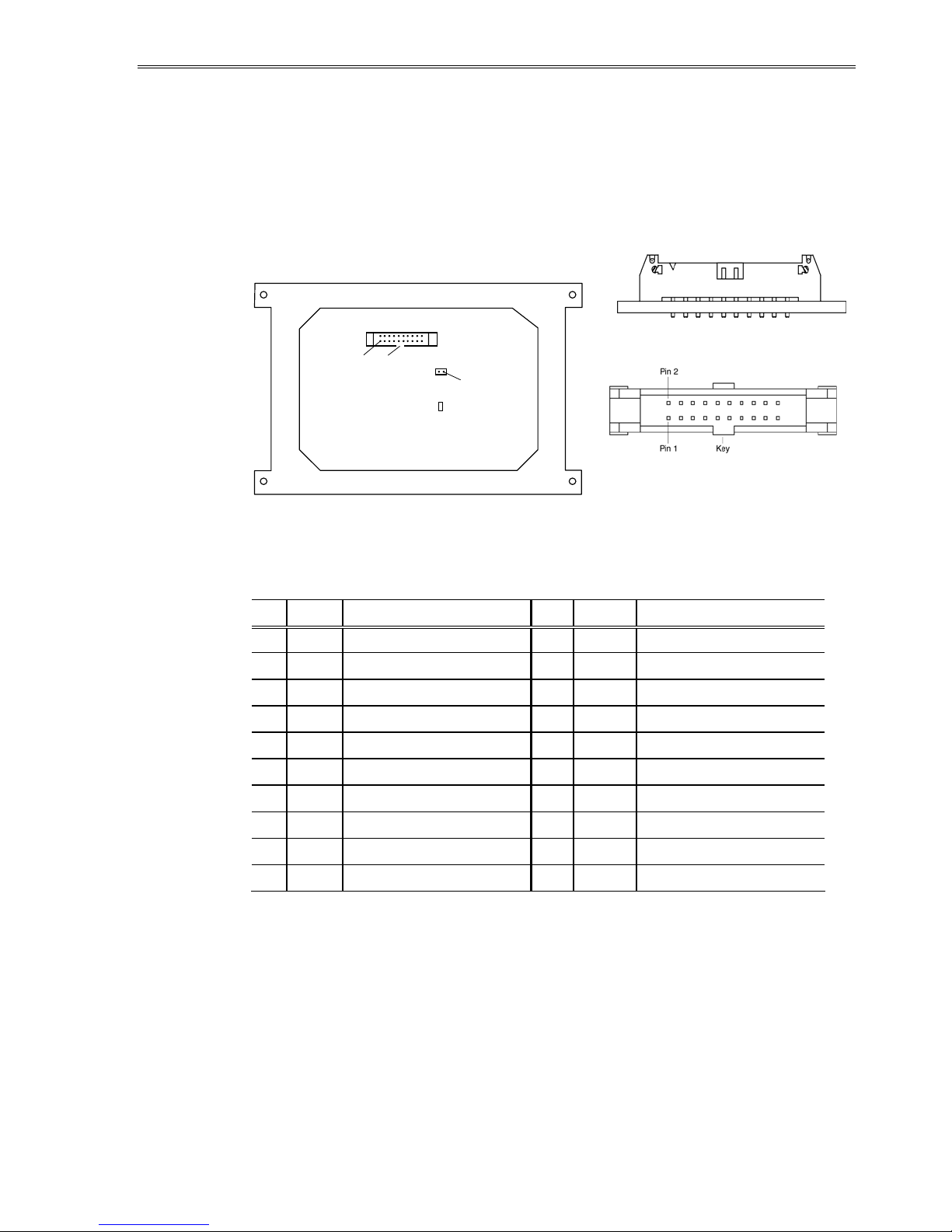
AM1 Data and Power Connector................................................................................................................
7
AM8 Data and Power Connector................................................................................................................
8
Locking Power and Data Connector .........................................................................................................9
Dimming Connector J2..................................................................................................................................
9
Interfacing ...............................................................................................................................................................9
Video Input Signals........................................................................................................................................
10
Self-Test Mode......................................................................................................................................................12
Optical Performance..........................................................................................................................................13
Dimming ...........................................................................................................................................................
13
Grayscale...........................................................................................................................................................
14
Reliability................................................................................................................................................................14
Safety and EMI......................................................................................................................................................14
Environmental......................................................................................................................................................15
Mechanical Characteristics..............................................................................................................................15
Component Envelope .......................................................................................................................................16
Description of Warranty ........................................................................................................................................17
Ordering Information.............................................................................................................................................18
Support and Service................................................................................................................................................18

Figures
Figure 1. AM1 Data/Power Connector...........................................................................................................7
Figure 2. AM8 Connector Locations...............................................................................................................8
Figure 3. Video Input Timing Diagram........................................................................................................10
Figure 4. Setup and Hold Timing Diagram. ...............................................................................................11
Figure 5. Data Format........................................................................................................................................12
Figure 6. AM Series Dimensions.....................................................................................................................16
Tables
Table 1. DC Input Voltage Requirements. ....................................................................................................6
Table 2. Video Input Requirements. ...............................................................................................................6
Table 3. J1 Connector Pinouts..........................................................................................................................8
Table 4. Video Input Timing. ...........................................................................................................................10
Table 5. Setup and Hold Timing.....................................................................................................................11
Table 6. Optical Characteristics......................................................................................................................13
Table 7. Environmental Characteristics.......................................................................................................15
Table 8. Dimensions and Weight...................................................................................................................15

EL640.480-AM Operations Manual (020-0351-00C) 3
AM Series 10.4” VGA Flat Panel Displays
This manual supports these Planar ICEBrite displays:
• EL640.480-AM1
• EL640.480-AM1 AG
• EL640.480-AM8 IN (Industrial version)
• EL640.480-AM8 ET (Extended Temperature version)
• EL640.480-AM8 ET CC (ET with conformally coated board)
• EL640.480-AM8 ETL (Extended Low Temperature version)
• EL640.480-AM8 ETL CC (ETL with conformally coated board)
The AM series of 10.4" diagonal VGA products offers designers an affordable
and easily-implemented path to incorporate flat panel solutions to meet
display requirements.
Utilizing Planar’s proprietary ICEBrite technology (Integrated Contrast and
Brightness Enhancement), these displays excel in ambient light environments
ranging from dark rooms to nearly sunlight. This proprietary technology
achieves very high contrast and exceptionally clear images. These displays are
easy to integrate, enabling the quick replacement of existing LCDs. This family
utilizes a common 8-bit FPD-type interface compatible with most LCD video
controller chips. Up to five distinct gray levels are enabled by frame rate
modulation algorithms generated by the controller chips.
Through simple design and advanced manufacturing technologies, Planar’s
new VGA displays bring the visual performance and image quality of
electroluminescence (EL), long life, and ruggedness into cost-sensitive
applications.
Features
• Excellent viewing characteristics
• High brightness and contrast
• Wide viewing angle
• Long life
• Extreme ruggedness
• Designed for low EMI
• Fast response time
• Lower power

EL640.480-AM Operations Manual (020-0351-00C)
4
Options
Anti-glare and conformal coating options are available on this display.
The anti-glare option adds an anti-glare film to the front of the display to
reduce specular reflections (see Application Note 135 for more information).
The conformal coating option adds a protective layer to the display for
applications in which the display may be subjected to high humidity, dust, or
salt mist (see Application Note 122 for more information).
Installation and Handling
The mechanical package consists of the display panel and electronic circuit
board bonded together, plus a protective cover carrying the display mounting
ears. The display is made of glass material and must be handled with care.
CAUTION: The display uses CMOS and power MOSFET devices. These
components are electrostatic sensitive. Unpack, assemble, and examine this
assembly in a static-controlled area only. When shipping, use packing
materials designed for protection of electrostatic-sensitive components.
Do not drop, bend, or flex the display. Do not allow objects to strike the
surface of the display.
Mounting EL Displays
The EL640.480 AM displays were designed to facilitate the mounting of optical
treatments and touchscreens on the viewing side of the display. To this end,
the glass extends in front of the mounting bezel by approximately 0.5 mm
(0.02 in.). It is imperative that any mounting scheme apply uniform pressure at
all times across the glass. Pressure applied to the corners or edge of the glass is
likely to cause breakage.
Mounting should be done using the mounting ears only. Use either metric M3
screws torqued to 350 Ncm maximum, or unified #4 screws torqued to 4.7
in/lb maximum.
CAUTION: Properly mounted, this display can withstand high shock loads
and severe vibration in aggressive environments. However, the glass panel
used in this display will break when subjected to bending stresses, high
impact, or excessive loads.
To prevent injury in the event of glass breakage, a protective overlay should
be used on the viewer side of the display.
WARNING: These products generate voltages capable of causing personal
injury (high voltage up to 200 Vac ). Do not touch the display electronics
during operation.

EL640.480-AM Operations Manual (020-0351-00C) 5
Cable Length
The maximum recommended cable length is 600 mm (24 in.). Longer cables
may cause data transfer problems between the data transmitted and the
display input connector. Excessive cable lengths can pick up and source
unwanted EMI. There are third party products which allow this maximum cable
length to be exceeded. Contact Planar Application Engineering for more
information.
Cleaning
As with any glass or coated surface, care should be taken to minimize
scratching. Clean the display glass with mild, water-based detergents only.
Apply the cleaner sparingly to a soft cloth, then wipe the display. Disposable
cleaning cloths are recommended to minimize the risk of inadvertently
scratching the display with particles embedded in a re-used cloth. Particular
care should be taken when cleaning displays with anti-glare and anti-reflective
films.
The TAB (tape-automated bonding) leads between the electronics and the
display glass are very sensitive to handling. When cleaning the edges of the
display glass, special care should be taken not to damage the leads.
Avoiding Burn-In
As with other light emitting displays, displaying fixed patterns on the screen
can cause burn-in, where luminance variations can be noticed. Use a screen
saver or image inversion to avoid causing burn-in on the display.

EL640.480-AM Operations Manual (020-0351-00C)
6
Specifications
The EL panel is a matrix structure with column and row electrodes arranged in
an X-Y formation. Light is emitted when an AC voltage of sufficient amplitude
is applied at a row-column intersection. The display operation is based on the
symmetric, line at a time data addressing scheme. Operating voltages required
are provided by a DC/DC converter.
Unless otherwise specified, performance characteristics are guaranteed when
measured at 25°C.
Power
The supply voltages required for the displays are shown in Table 1. All internal
high voltages are generated from display supply voltage (VH). The logic supply
voltage (VL) should be present whenever video input signals or VHis applied.
Table 1. DC Input Voltage Requirements.
AM1, AM8 ETL AM8 IN/ET Notes
12 V 24 V
VL+5 V ±5% +5 V ±5% +5 V ±5% absolute max 7.0 V
VH+12 V ±10% +12 V ±10% +24 V ±10% absolute max. 15 V
and 30 V
respectively
IL, max 75 mA 75 mA 75 mA @ VL= +5 V
IH, max 2.0 A 2.0 A 1.0 A @ VH= +12 V
Ptyp, 120 Hz 11 W 11 W 11 W 3840 'E' characters
Pmax, 120 Hz 24 W 24 W 24 W 50/50 2x2
checkerboard
CAUTION: Absolute maximum ratings are those values beyond which
damage to the device may occur.
Table 2. Video Input Requirements.
Description Min Max Notes
Video logic high voltage 3.7 V 5.0 V All input thresholds are
CMOS
Video logic low voltage 0 V 0.9 V Video lines have 100 Ω
series resistors
Video logic input current – 10 µA +10 µA
There is no overcurrent protection on either the VHor VLinputs to protect
against catastrophic faults. Planar recommends the use of a series fuse on the
12 volt supply. A general guideline is to rate the fuse at 1.8 to 2 times the
display maximum current rating.

EL640.480-AM Operations Manual (020-0351-00C) 7
Input Voltage Selection
The AM8 displays (except AM8 ETL) feature a jumper
that allows the user to choose between 12 and 24 volt
supply voltage. The displays are shipped with the JP1
jumper in the pin 1/pin 2 position which sets the
supply voltage at 12 volts.
To select a 24 volt supply, move the JP1 jumper to the
pin2/pin3 position. Pin one is marked on the +12 V
end of JP1.
CAUTION: Providing a 24 volt supply to the display when the jumper is in the
12 volt supply position will damage the display.
The display will not function if the jumper is removed completely. Planar
recommends the use of a non-conductive adhesive to secure the jumper in
the desired position in environments where shock or vibration might loosen
the jumper.
The minimum and maximum specifications in the manual should be met,
without exception, to ensure the long-term reliability of the display. Planar
does not recommend operation of the display outside these specifications.
Connectors
AM1 Data and Power Connector
The AM1 displays use the Samtec STMM-110-01-S-D or equivalent connector,
and the AM8-IN displays use the Samtec STMM-110-01-T-D or equivalent
connector. The mating connector for both the AM1 and AM8-IN displays is in
the Samtec TCSD family of cable strips. The proper connector, user-specified
cable length, and connector configuration are supplied as a single unit.
Consult your Samtec representative (1 800-SAMTEC9) for the cable/connector
options.
Figure 1. AM1 Data/Power Connector
JUMPER PLUG
(2 PIN)
+24V
+12V
JP1
KEY
PIN 1

EL640.480-AM Operations Manual (020-0351-00C)
8
AM8 Data and Power Connector
The standard data and power connector for the AM8 displays is a Samtec
ASP-61606-01-M or equivalent, J1 20-pin, 2mm pitch (Figure 2. Connector
Locations). The mating connector is in the Samtec TCSD family of cable strips.
The proper connector, user-specified cable length, and connector
configuration are supplied as a single unit. Consult your Samtec representative
(1 800-SAMTEC9) for the cable/connector options.
Figure 2. AM8 Data/Power Connector
Table 3. J1 Connector Pinouts.
Pin Signal Description Pin Signal Description
1 UD1 Video data (upper) 2 UD0 Video data (upper)
3 UD3 Video data (upper) 4 UD2 Video data (upper)
5 LD1 Video data (lower) 6 LD0 Video data (lower)
7 LD3 Video data (lower) 8 LD2 Video data (lower)
9 CP2 Pixel clock 10 GND Ground
11 CP1 Line pulse 12 GND Ground
13 S Frame pulse 14 GND Ground
15 GND Ground 16 GND Ground
17 VL+5 V logic supply 18 VL+5 V Logic supply
19 VH+12/24 V Display supply 20 VH+12/24 V Display supply
J1 Side View
J1 Top View
J2
JP1
J1
Pin 1
Pin 1 Key

EL640.480-AM Operations Manual (020-0351-00C) 9
Locking Power and Data Connector
The AM8 IN display may be ordered with an optional 20
pin, 2 mm through-hole locking male header, Samtec
EHT-110-01-S-D or equivalent. The locking connector
is standard on the AM8 ET and AM8 ETL. The locking
connector adds 2.0 mm to the display depth.
The Samtec mating connector for the non-locking
power and data connector on the AM1 and AM8 IN
will mate with the locking connector. Compatibility
with non-Samtec equivalents should be verified
before use.
Dimming Connector J2
An analog dimming circuit is standard on the AM8. The
J2 dimming connector is a Molex 2-pin, right angle
locking male, part number 22-12-2024. The
recommended mating connector is a Molex 22-01-3027
(housing) and 08-52-0123 (crimps, 2 per housing).
Additionally the crimp housing will need crimp terminals
to connect the wires, Molex 2759 or 6459 can be used.
Molex crimp terminal 41527 is recommended for applications with high
vibration requirements.
For a discussion of the dimming feature, refer to the Dimming section below,
under Optical Performance.
Interfacing
This dual scan LCD-type video interface provides a low cost, flexible method
for controlling display brightness and power consumption. Many off-the-shelf
chipsets are available for interfacing to flat panel displays. If your application
does not require chip-level integration, there are many vendors that can
supply board-level solutions for serial control, PC104, ISA, and many other
interfaces.
Planar Application Note 116 summarizes some of the interfacing options that
have been used in the past with EL VGA displays.

EL640.480-AM Operations Manual (020-0351-00C)
10
Video Input Signals
The end of the top line of a frame is marked by S, scan start up signal as shown
in Figure 3. The end of each row of data is marked by CP1 as shown in Figure 3
and Figure 4.
S (FRAME)
CP1 (LINE)
UD0 to UD3
LD0 to LD3 frame n- 1 frame n frame n+ 1
row 240/480 row 1/241
row 1/241
160 CP2 pulses
CP1 (L:INE)
UD0 to UD3
LD0 to LD3 First pixels (1...4) Last pixels (637...640)
240 CP1 pulses
T1
T2 T3
Figure 3. Video Input Timing Diagram.
Table 4. Video Input Timing.
Symbol Name Min Max Units
T1 Frame time 8.3 --- ms
Frame frequency --- 120 Hz
T2 CP1 High time 60 --- ns
T3 CP1 Period 34.5 --- µs

EL640.480-AM Operations Manual (020-0351-00C) 11
S (FRAME)
CP1 (LINE)
UD0 to UD3
LD0 to LD3
CP2 (SHIFT) tSU tHOLD
tFtR tS21 tS12
tF
tR
tSU tHOLD
tS3
tCLK
tCL tCH
Figure 4. Setup and Hold Timing Diagram.
Table 5. Setup and Hold Timing.
Symbol Name Min. Max Unit
tS21 CP1 allowance from CP2 0 ns
tS12 CP2 allowance from CP1 200 ns
tS3 CP1 allowance to CP2 50 ns
tSU Setup time 50 ns
tHOLD Hold time 40 ns
tR Rise time 30 ns
tF Fall time 30 ns
tCLK CP2 clock cycle 154 ns
tCL CP2 clock low time 60 ns
tCH CP2 clock high time 60 ns
Input signals UD0 through UD3 contain the video data for the upper screen
and signals LD0 through LD3 contain the data for the lower screen. For
example, four pixels (UD3:1,1–UD0:1,1) are sent to row 1 at the same time as
four pixels (LD0:1,1–LD3:1,1) are sent to row 241. This results in eight pixels
sent on each cycle of video clock CP2. Pixel information is supplied from left to
right and from top to bottom. Video data for one row is latched on the fall of
CP1 (Figure 5).

EL640.480-AM Operations Manual (020-0351-00C)
12
CP1 (LINE)
CP2 (SHIFT)
UD3
UD2
UD1
UD0
LD3
LD2
LD1
LD0
Row 1
Row 2 4 1 Row 2 4 2
Row 2
1
2
3
4
5
6
7
8
9
10
11
12
629
630
631
632
633
634
635
636
637
638
639
640
1
2
3
4
1
2
3
4
5
6
7
8
9
10
11
12
629
630
631
632
633
634
635
636
637
638
639
640
1
2
3
4
nPixel no.
Figure 5. Data Format.
Self-Test Mode
The display incorporates a self-test mode composed of a 1x2 checkerboard
pattern that inverts every few seconds. The self-test mode is entered by
applying power to the display with the Ssignal static. The display remains in
this mode until two (2) low-to-high transitions of the Ssignal are detected. The
display then enters and remains in normal (user video driven) operation as
long as power is applied. To enter self-test mode again, the display must be
reset by cycling the VHpower input.

EL640.480-AM Operations Manual (020-0351-00C) 13
Optical Performance
Table 6. Optical Characteristics.
Luminance Lon (areal), min Lon (areal), typ Loff (areal), max
AM1
AM8 IN/ET/ETL
40 cd/m²
35 cd/m²
65 cd/m²
49 cd/m²
0.3 cd/m²
0.3 cd/m²
Minimum and Typical: Center, 120 Hz frame rate
Maximum: Center and four corners, 120 Hz frame rate
Non-uniformity
AM1
AM8 IN/ET/ETL
35%
26%
All pixels fully on @120 Hz
Maximum difference two of five points,
using the formula:
BNU%=[1- (min_lum/max_lum)] x 100%
Luminance Variation (Temperature)
Maximum 15% Across operating temperature range
Luminance Variation (Time)
Maximum
AM1
AM8 IN/ET/ETL
20%
10%
10,000 hours at 25°C ambient
Viewing Angle
Minimum 160°
Contrast Ratio Minimum Typical
AM1
AM8 IN/ET/ETL
19:1
35:1
40:1
70:1
Minimum: @ 500 lux ambient, @ 120 Hz frame rate
Dimming
There are two standard methods for dimming the AM displays. Frame rate
dimming allows the brightness of the display to be lowered proportionally by
reducing the frame rate. Analog dimming allows the brightness to be reduced
with an external, user supplied potentiometer or electronic circuitry. The
brightness range for analog dimming is from 100% to nearly 5% of the full
brightness.
Frame rate dimming is performed within the application by lowering the
frame rate of the video input signals. Because brightness is proportional to
refresh rate, the display can be dimmed by adding pauses between every
horizontal period.
The lowest possible frame rate (brightness) is dependent on the perceived
flicker of the displayed image, but will most likely be around 60 Hz. For more
information on frame rate dimming please see Planar Application Note 120.
The analog dimming feature utilizes a 50k ohm logarithmic external
potentiometer, allowing manual control of the display’s brightness. Analog
dimming is standard on the AM8 IN and AM8 ET displays. The typical current
for minimum brightness is 220 µA.

EL640.480-AM Operations Manual (020-0351-00C)
14
Grayscale
Using the display’s higher frame rate frequency, combined with flat panel
controllers, it is possible to generate a wider range of usable grayscales
through frame rate control and dithering.
Frame Rate Control
generates true grayscales by turning pixels on and off over
several frames of time. The user’s eye sees each individual pixel as gray. The
potential problems with this method are brightness-profile and shadowing,
especially when used to shade larger areas.
Dithering
generates grayscales by patterning the area to be shaded. The
tested C&T controllers use a pattern of 4 (2x2) pixels to generate the dithered
grayscales. When the area is viewed from a distance, it appears to the user’s
eye as gray. When viewed up close, the different brightness of the individual
pixels can be observed.
Many of the grayscales that can be generated may flicker or swim. Through
careful selection however, several grayscale patterns are available for most
applications, particularly when the display is driven at its maximum frame rate
frequency. Planar Application Note 119 is available for more information on
generating grayscale images.
Reliability
The MTBF (mean time between failures) is a minimum of 50,000 hours at 25°C
ambient, except for performance characteristics with an otherwise specified
life expectancy.
Safety and EMI Performance
The AM displays will not inhibit the end product from obtaining these
certifications:
Safety: UL544, IEC950
EMI: FCC Part 15/J, Class B
EN55022 Level B

EL640.480-AM Operations Manual (020-0351-00C) 15
Environmental
Table 7. Environmental Characteristics.
Temperature AM1 AM8 IN AM8 ET……………..AM8ETL
Operating
Non-Operating
Operating Survival
-5 to +55°C
-40 to +75°C
-20 to +65°C
-25 to +65°C
-40 to +75°C
-40 to +70°C
-40 to +65°C……..-60 to +65°C
-40 to +75°C……..-60 to +75°C
-40 to +70°C……..-60 to +70°C
Humidity
Non-condensing 93% RH max +40°C per IEC 68-2-3.
Altitude AM1 AM8
Operating
0 to 5 km
(16k ft)
0 to 18 km
(58k ft)
Non-Operating 0 to 18 km (58k ft) per IEC 68-2-13
Vibration
Random 0.02 g²/Hz
ASD level, 20-500 Hz per IEC 68-2-36, test Fdb
Shock
Half sine wave 100 g, 4 ms 18
(3 each, 6 surfaces) per IEC 68-2-27, test Ea
Mechanical Characteristics
Table 8. Dimensions and Weight.
Display Size 266.0 x 192.0 (W x H)
Display Depth 20.0 (AM1), 15.8 (AM8 IN), 17.8 (AM8 ET/ETL)
Active Area 211.1 x 158.3 (W x H)
Fill Factor 57%
Pixel Pitch 0.33 x 0.33
Pixel Size 0.25 x 0.25
Weight (typical) 650 g
All dimensions are in millimeters, unless otherwise noted.

EL640.480-AM Operations Manual (020-0351-00C)
16
Component Envelope
Figure 6 illustrates the mechanical dimensions and the distance components
extend behind the display. Tall components do not necessarily fill this area.
Planar reserves the right to relocate components within the constraints of the
component’s envelope without prior customer notification. For this reason,
Planar advises users to design enclosure components to be outside
thecomponent envelope.
Dimensions are in millimeters, brackets are in inches.
Tolerances, unless otherwise stated, are ±0.2 mm.
Figure 6. AM Series Dimensions.

EL640.480-AM Operations Manual (020-0351-00C) 17
Description of Warranty
Seller warrants that the Goods will conform to published specifications and be free from defects in
material for 12 months from delivery. To the extent that Goods incorporate third-party-owned
software, Seller shall pass on Seller's licensor's warranty to Buyer subject to the terms and conditions
of Seller's license.
Warranty repairs shall be warranted for the remainder of the original warranty period. Buyer shall
report defect claims in writing to Seller immediately upon discovery, and in any event, within the
warranty period. Buyer must return Goods to Seller within 30 days of Seller’s receipt of a warranty
claim notice and only after receiving Seller’s Return Goods Authorization. Seller shall, at its sole
option, repair or replace the Goods.
If Goods were repaired, altered or modified by persons other than Seller, this warranty is void.
Conditions resulting from normal wear and tear and Buyer's failure to properly store, install, operate,
handle or maintain the Goods are not within this warranty. Repair or replacement of Goods is
Seller’s sole obligation and Buyer's exclusive remedy for all claims of defects. If that remedy is
adjudicated insufficient, Seller shall refund Buyer's paid price for the Goods and have no other
liability to Buyer.
All warranty repairs must be performed at Seller’s authorized service center using parts approved by
Seller. Buyer shall pay costs of sending Goods to Seller on a warranty claim and Seller shall pay costs
of returning Goods to Buyer. The turnaround time on repairs will usually be 30 working days or less.
Seller accepts no added liability for additional days for repair or replacement.
If Seller offers technical support relating to the Goods, such support shall neither modify the
warranty nor create an obligation of Seller. Buyer is not relying on Seller’s skill or judgment to select
Goods for Buyer’s purposes. Seller’s software, if included with Goods, is sold as is, and this warranty
is inapplicable to such software.
SELLER DISCLAIMS ALL OTHER WARRANTIES, EXPRESS OR IMPLIED, INCLUDING BUT NOT LIMITED
TO, IMPLIED WARRANTIES OF MERCHANTABILITY AND FITNESS FOR A PARTICULAR PURPOSE.

EL640.480-AM Operations Manual (020-0351-00C)
18
Ordering Information
Product Part Number Description
EL640.480-AM1 996-0268-00LF 10.4" diagonal, 640x480 VGA display.
0 to 55°C operating temperature
EL640.480-AM1 AG 996-0268-02LF EL640.480-AM1 with anti-glare film
EL640.480-AM8 IN 996-0268-27LF 10.4" diagonal, 640x480 VGA display.
-25 to 65°C operating temperature, analog
dimming, low profile, optional 24 V supply
EL640.480-AM8 ET 996-0268-16LF 10.4" (mm) diagonal, 640x480 VGA display.
-40 to 65°C operating temperature, analog
dimming, low profile, optional 24 V supply,
locking data and power connector.
EL640.480-AM8 ET CC 996-0268-20LF EL640.480-AM8 ET with conformal coating
EL640.480-AM8 ETL 996-0268-28LF 10.4" (mm) diagonal, 640x480 VGA display.
-60 to 65°C operating temperature, analog
dimming, low profile, locking data and power
connector.
EL640.480-AM8 ETL CC 996-0268-29LF EL640.480-AM8 ETL with conformal coating
Design and specifications are subject to change without notice.
Planar Systems continues to provide optional, and in many cases custom, features to address the
specific customer requirements. Consult Planar Sales for pricing, lead time and minimum quantity
requirements.
Support and Service
Planar Systems, Inc. is a US company based in Beaverton, Oregon and Espoo, Finland, with a
world-wide sales distribution network. Full application engineering support and service are
available to make the integration of Planar displays as simple and quick as possible for our
customers.
RMA Procedure: For a
Returned Material Authorization
number, please contact Planar Systems, Inc.
with the model number(s) and serial number(s). When returning goods for repair, please include a
brief description of the problem, and mark the outside of the shipping container with the RMA
number.
Table of contents
Other Planar Monitor manuals

Planar
Planar PLL1911M User manual

Planar
Planar PS5074K User manual

Planar
Planar PT1945RW User manual

Planar
Planar PS Series User manual

Planar
Planar PT150M User manual

Planar
Planar CT1904Z User manual

Planar
Planar SD2220W User manual

Planar
Planar LO552 User manual

Planar
Planar M40L User manual

Planar
Planar PXN2410 User manual

Planar
Planar PS4660T User manual

Planar
Planar PT1503NT User manual

Planar
Planar CT1744NU User manual

Planar
Planar PL2011 User manual

Planar
Planar CM17.4SXAD User manual

Planar
Planar Dome Q2 User manual

Planar
Planar SD2421W User manual

Planar
Planar PLL1500M User manual

Planar
Planar SD2420W User manual

Planar
Planar LX1501PTI User manual