Planer BT37-02 User manual

®
INSTRUCTIONS FOR USE
BT37 v2
MA200214-M-EN 2.0.24


3
Table of contents
1. Introduction 5
1.1 Notices ............................................................................................................................ 6
1.2 Intended use ................................................................................................................... 6
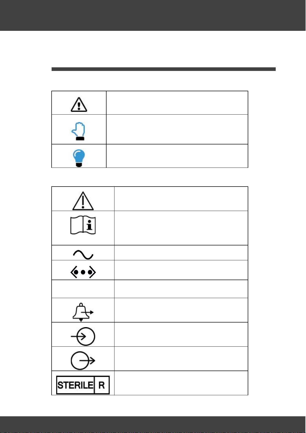
1.3 Symbols ........................................................................................................................... 7
1.3.1 Symbols used in this manual .................................................................................... 7
1.3.2 Symbols used on the equipment .............................................................................. 7
1.4 Safety .............................................................................................................................. 8
1.4.1 Warnings .................................................................................................................. 8
1.4.2 Precautions ............................................................................................................... 9
1.4.3 Electromagnetic compatibility (EMC) .................................................................... 10
1.5 About the equipment .................................................................................................. 10
1.5.1 Theory of operation ................................................................................................ 10
1.5.2 Front view ............................................................................................................... 11
1.5.3 Side view ................................................................................................................ 12
1.5.4 Rear view ................................................................................................................ 13
1.5.5 User interface ......................................................................................................... 13
1.5.5.1 Numeric entry .......................................................................................................................................... 15
1.5.5.2 Menus ....................................................................................................................................................... 15
1.5.6 Status and alarm indicators ................................................................................... 16
1.5.6.1 Acknowledging an alarm ...................................................................................................................... 16
2. Installation 17
2.1 Connecting the gas supply .......................................................................................... 19
2.2 External data collection .............................................................................................. 19
2.3 Connecting the external alarm ................................................................................... 20
2.4 Connecting to the mains supply ................................................................................. 20
3. Operation 21
3.1 Setting the access code ............................................................................................... 23
3.2 Changing the control settings ..................................................................................... 23
3.2.1 Gas flow ................................................................................................................. 24
3.2.1.1 Non-pulsed bleed flow .......................................................................................................................... 24
3.2.1.2 Pulsed bleed flow ................................................................................................................................... 24
3.3 Installing the humidifier .............................................................................................. 25
3.3.1 Single tube bottle humidifier .................................................................................. 27
3.4 Switching off ................................................................................................................ 30
4. Routine maintenance and troubleshooting 33
4.1 Regular checks .............................................................................................................. 34
4.2 General cleaning .......................................................................................................... 34
4.3 Cleaning and disinfecting the chamber ..................................................................... 35
4.4 Checking the liquid level indicator ............................................................................. 36

4
Table of contents
4.5 Checking the battery ................................................................................................... 36
4.6 Calibration and servicing ............................................................................................. 37
4.7 Safety testing ............................................................................................................... 38
4.8 Testing the alarms ........................................................................................................ 39
4.9 Troubleshooting ........................................................................................................... 40
4.9.1 Normal messages ................................................................................................... 41
4.9.2 Control errors ......................................................................................................... 42
4.9.3 Battery errors ......................................................................................................... 43
4.9.4 Miscellaneous errors .............................................................................................. 43
4.9.5 Condensation ......................................................................................................... 43
4.9.6 Resetting the access code ..................................................................................... 44
4.9.7 Resetting the system ............................................................................................. 44
4.10 Returning for service ................................................................................................... 45
4.11 Disposal ......................................................................................................................... 45
5. Additional information 47
5.1 External alarm connection .......................................................................................... 48
5.2 Network security ......................................................................................................... 48
5.3 Specifications ............................................................................................................... 49
5.3.1 System .................................................................................................................... 49
5.3.2 Control .................................................................................................................... 49
5.3.3 Capacity .................................................................................................................. 50
5.3.4 Power ...................................................................................................................... 50
5.3.4.1 Internal battery ....................................................................................................................................... 50
5.3.5 Humidifier bottle and filter .................................................................................... 51
5.3.6 Gas supply .............................................................................................................. 51
5.3.7 External alarm connections .................................................................................... 51
5.3.8 Monitoring .............................................................................................................. 52
5.3.9 Fuses ...................................................................................................................... 52
53
Index

Introduction

6
Introduction
1 Introduction
This manual only applies to the following models: BT37-02
This guide has been designed to help you install and use the BT37-02. The guide
includes important information regarding safe use of the equipment and it is important
that you familiarise yourself with this document before attempting to install or operate
the equipment.
1.1 Notices
INSTRUCTIONS FOR USE: BT37 v2
Issue: 2.0.24 2020-06-01
© 2020 Planer Limited
Original Instructions
Planer Limited. 110 Windmill Rd., Sunbury-on-Thames, Middlesex,
TW16 7HD, UK. Tel: +44 (0)1932 755000; email: sales@planer.com
1639
Product names and designations that are referred to in this document may be either
trademarks and/or registered trademarks and are recognised as the property of their
respective owners.
This information is provided without warranty, express or implied, and including but not
limited to any implied warranties in respect of merchantability or fitness for any purpose,
except to the extent that such provisions are held to be void, in violation of applicable law
or unenforceable in a specific jurisdiction.
Planer Limited reserves the right to alter products and their specifications without notice.
1.2 Intended use
The BT37-02 is intended to be used to provide an environment with controlled
temperature at or near body temperature, carbon dioxide, oxygen and nitrogen gases,
and elevated humidity for the development of gametes and embryos during in vitro
fertilization (IVF) / assisted reproductive technology (ART) treatments.
USA: Caution
By prescription only. Rx only. Caution: Federal law restricts this device to sale by or
on the order of a physician or a practitioner trained in its use.

7
Introduction
1.3 Symbols
1.3.1 Symbols used in this manual
This symbol shows information or instructions that are related
to safety. Failure to follow these instructions may result in
personal or third-party injury.
This symbol is used to introduce important information or
instructions related to use of the product. Failure to follow
these instructions may result in damage to the equipment,
samples or data.
The light bulb symbol is used to highlight information and tips
that may help you get the best from your product.
1.3.2 Symbols used on the equipment
Refer to these instructions. Failure to follow these
instructions may result in personal or third-party injury.
eIFU indicator
Consult instructions for use. Electronic instructions can be
accessed from the eIFU indicator web address.
Alternating current (AC).
Ethernet connection.
RST Reset switch. Only press if the system becomes
unresponsive.
Alarm output connector.
Premixed gas inlet.
Premixed gas outlet.
Sterilized using irradiation

8
Introduction
Do not reuse.
Do not use if packaging is broken.
Do not resterilize.
Batch code.
Use by date.
Do not dispose of with general waste.
Rx only USA: Caution: Federal law restricts this device to sale by or on the order
of a physician or a practitioner trained in its use.
1.4 Safety
1.4.1 Warnings
Operating the equipment in a manner not specified within this manual or under
conditions outside of the equipment specifications, may result in the protection offered
by the equipment being impaired.
Use in well ventilated areas. Risk of asphyxiation from carbon dioxide released from
the equipment. Additional ventilation may be required. Consider carbon dioxide alarms
in confined spaces. Refer to the Gas supply topic for gas release rates.
Never connect to flammable or oxidising gas mixtures.
Do not connect to a gas supply with a pressure exceeding 1.65 bar.
Take care when handling samples. Samples may present other biological hazards.
Refer to the person responsible for the equipment.
51

9
Introduction
Do not attempt to charge the battery externally. The BT37-02 contains a sealed lead
acid battery. Over-charging can result in the release of dangerous gases. Refer to the
Internal battery topic for details.
Equipment must be earthed. Class 1.
Supply power via a residual current circuit breaker (RCCB) operating at a differential of
30 mA.
To avoid risk of fire, fuses must always be replaced with the same type and rating.
oFuses should only be replaced by suitably trained service personnel.
oFuses should only be replaced after the cause of the original failure has been
determined and corrected as appropriate.
1.4.2 Precautions
Ensure the equipment and mains cords are regularly checked by a competent person,
using a Portable Appliance Tester or similar equipment, to ensure adequate earth
bonding.
Ensure the earth continuity of the mains installation is regularly inspected by a
competent person.
Check the voltage requirements of the equipment, shown on the rating label, match
the local mains supply.
The mains lead to the power supply is the main disconnect device. If power needs to
be disconnected immediately, disconnect the mains lead from the power supply or
switch off at the mains power outlet.
Ensure the equipment is positioned so that the mains lead can be easily
disconnected.
Connected devices must comply with EN60950 or its equivalent.
To ensure you can respond to alarm conditions when the laboratory is unattended, the
equipment should be connected to an independent, external alarm system.
The alarm output must not be used in safety-critical applications.
oAny circuit connected to the alarm output must meet the requirements for an
accessible part as defined in EN 61010-1 or its equivalent.
Do not connect to Ethernet local area networks (LAN) external to the building.
User servicing is limited to cleaning and calibration.
Ensure cables do not cause a trip hazard.
Take care when lifting. Uneven load: 17 kg.
Keep the humidifier lid closed during normal operation.
Operating parameters should only be modified by qualified service personnel or under
their guidance. Entering incorrect values may impair the performance of the product.
The internal battery can only support the incubator for up to 2 hours if mains power
fails. This time is dependent on the battery condition and operating conditions.
50

10
Introduction
1.4.3 Electromagnetic compatibility (EMC)
The equipment is intended for use in a basic electromagnetic environment, characterised
by being supplied directly at low voltage from the public mains network.
All connections via the External alarm connection must use fully screened cable
no longer than 2 m.
Take care to avoid placing the BT37-02 in environments influenced by sources of
electromagnetic interference, such as large transformers for example.
1.5 About the equipment
1.5.1 Theory of operation
The basic principle of operation is illustrated in the diagram below.
Samples are placed in dishes in the left and right chambers which are heated to
maintain a constant temperature. Pre-mixed gas is supplied from a pressurised cylinder,
bubbled through water contained in the humidifier bottle, and then passed to the left and
right chambers. This results in the samples being maintained at a controlled temperature
and within a controlled atmosphere.
If the lids are opened and then shut again, gas is provided at an increased flow rate to
reduce the time taken to restore the chambers back to the required gas concentration.
The BT37-02 can be in one of three modes: Standby, Run and Bottle change.
48

11
Introduction
Mode Heaters Gas Note
Standby Off Off The system is
inactive and ready to
be switched off.
Bottle change On Off The system is
waiting for the
humidifier to be
changed.
Run Controlled Controlled This is the normal
operating state.
1.5.2 Front view
1. Chamber lid and catch.
2. Humidifier lid.
3. Status indicators.
4. Touchscreen display.
5. Liquid level indicator.
The lids are fitted with rotary catches.
1. To open a lid, rotate the knob anticlockwise and lift the lid.
2. To close a lid, ensure the knob is rotated anticlockwise so it can engage with the pin
on the main body.
3. Gently lower the lid, and when it is fully closed, rotate the knob clockwise until it is
felt to latch.
The BT37-02 will not regard a lid as being shut until it is both closed and the knob
rotated clockwise into its locked position.

12
Introduction
1.5.3 Side view
1. Rear of base monitoring port for independent temperature probes.
2. Lid monitoring port for independent temperature probes.
3. Front of base monitoring port for independent temperature probes.

13
Introduction
1.5.4 Rear view
1. Mains inlet.
2. Premixed gas inlet
3. Daisy-chain gas outlet
4. Gas vents
5. Alarm output.
6. Reset switch.
7. Ethernet output.
8. Access ports for pH monitoring; for use by service personnel only.
1.5.5 User interface
The BT37-02 is provided with a resistive touchscreen interface.
When the system is idle, the standby screen is shown.
Pressing the Run button, moves the BT37-02 out of standby and into its normal
operating mode.

14
Introduction
In normal operation, the display shows the current status of the incubator. Pressing the
Display button cycles through different screens, each of which shows different
information about the state of incubator. An example is shown below.
1. Left-hand chamber readings are shown on the left of the display
2. Humidification chamber readings are shown in the middle of the display.
3. Right-hand chamber readings are shown on the right of the display
4. Lid temperatures are shown at the top of the display above the humidification
chamber readings.
5. Base temperatures are shown at the bottom of the display below the humidification
chamber readings.
6. The current temperature readings are identified by the label CURRENT. If the
setpoints are displayed, the values are displayed in a yellow font and identified by th
e
label SETPOINT.
Other options can be found by selecting the MENU option, which will open the main
menu shown below.
To return to the main display, select Display mode.
All menus operate in the same way, with a set of options and UP and DOWN buttons
which can be used to scroll up and down if there are more options to display.

15
Introduction
Sub-menus also contain a BACK button which will take you back to the previous menu.
1.5.5.1 Numeric entry
Some screens require a numeric entry to be entered. At these screens a keypad
appropriate to the required entry will be displayed. The screen for an access code entry
is shown below.
1. Use the keypad to enter the required number.
2. Use DEL to erase an invalid entry.
3. Press OK to submit the entry or CANCEL to exit the menu option.
1.5.5.2 Menus
All menu options are shown below:
Display mode: Press to toggle through different presentations of the current incubator
readings and setpoints.
Change bottle: Select to change the humidifier. See the Installing the humidifier
section.
Configuration: Select to change the control settings or calibration settings.
Calibration settings should only be adjusted by trained service personnel.
oControl settings: Select to adjust the main incubator settings. See the Changing
the control settings section.
oCalibration offsets: Select to adjust the calibration settings. Calibration settings
should only be adjusted by trained service personnel. See the Calibration and
servicing section.
Test: Select to run the in-built tests. See the Testing the alarms section.
Set access code: Select to set the access code. See the Setting the access
code section.
Reset access code: Select to reset the access code if it has been forgotten. See the
Resetting the access code section.
Security: Select to allow the incubator settings to be temporarily modified via the
network. See the Network security section.
Standby: Select to place the incubator into standby mode. See the Theory of
operation and Switching off sections.
25
23
37
39
23
44
48
10 30

16
Introduction
1.5.6 Status and alarm indicators
The status indicators on the front of the BT37-02 show the current state of the system.
These are used along with an internal buzzer and the external alarm. The state of the
indicators, buzzer and external alarm in various states are shown below.
State Status
indicators
Buzzer External
alarm
Display
Standby Steady orange Off Off Standby
Normal Steady green Off Off Normal display
Unacknowledged
alarm
Flashing red On Off Alarm message
Unacknowledged
alarm for longer than
5 minutes
Flashing red On On Alarm message
Acknowledged alarm Steady red Off Off Normal display
Temperatures not
ready.
Steady orange Off Off Normal display
1.5.6.1 Acknowledging an alarm
When an alarm occurs, an alarm message is shown. An example is shown below:
1. To silence the alarm, press SILENCE.
2. To acknowledge the alarm, press OK. This will close the alarm message.

Installation

18
Installation
2 Installation
Caution
Ensure the equipment is positioned so that the mains lead can be easily
disconnected.
Ensure cables do not cause a trip hazard.
Take care when lifting. Uneven load: 17 kg.
Important
Keep away from hot or cold temperature sources such heaters or air-conditioning
units.
Keep away from sources of electromagnetic interference such as large transformers.
Maintain clear space around the incubator: 150 mm at the rear and at least 25 mm
at the front and sides.
Note
The location of the connectors is shown in the Rear view section.
1. Carefully unpack the equipment.
2. Install on a flat, level and stable surface.
3. Connect the gas supply; see Connecting the gas supply .
4. If the local area network is to be used to collect data, connect now; see External
data collection .
5. If an external alarm is to be used, connect now; see Connecting the external
alarm .
6. Clean and disinfect before use; see Cleaning and disinfecting the chamber .
7. Install the humidifier; see Installing the humidifier .
8. Connect the mains supply; see Connecting to the mains supply .
9. Press the Run button to leave standby mode and enter the normal run mode.
10. Ensure both status indicators turn green within 30 minutes.
11. Check bubbles can be seen flowing through the bottle; see Checking the liquid level
indicator .
12. From the main display, click Menu.
13. Select Standby. This will switch off the gas supply and stop heating the chambers.
13
19
19
20
35
25
20
36

19
Installation
2.1 Connecting the gas supply
Warning
The supply pressure must not exceed 1.65 bar.
Never connect to flammable or oxidising gas mixtures.
1. Consult your media supplier for the appropriate gas concentrations. The
concentration may need to be adjusted for local air pressure.
2. Only use medical-grade premixed gas, or medical-grade gases supplied via a gas
mixer.
3. Gas should be supplied at or around the normal lab temperature where the incubator
is being operated.
4. Any tubing used to connect the gas supply should be made of a material that is
impermeable to the premixed gas supply.
5. Clean tube fittings and blow through pipes with medical grade gas to clear any
foreign bodies before assembly.
6. Gas should be provided via a high purity gas regulator. The regulator will require a
SWAGELOK® SS-400-1-4RT fitting to match the hose supplied with the BT37-02.
7. It is recommended that a volatile organic compound (VOC) filter is fitted in the line.
8. Any pipework must be designed to supply at least 360 mL/min per incubator.
9. When tightening the hose fittings, assemble finger tight. Then using a 14.29 mm
(9/16 ") spanner, tighten a further 60 degrees. Do not over-tighten.
10. Connect the hose to the gas supply.
11. Connect the hose to the gas inlet of the incubator.
12. If daisy-chaining incubators:
a. Remove the blanking plug from the gas outlet of the first incubator.
b. Connect a hose from the gas outlet of the first incubator to the gas inlet of the
second.
c. A maximum of 10 incubators can be connected in series.
13. Use soapy water over the joints to check for leaks. If any bubbles are seen, gently
tighten the joint. If bubbles continue, switch off the gas supply, disconnect the hose
and check the fitting for any debris before reconnecting.
2.2 External data collection
The Ethernet connection on the rear of the BT37-02 can be used to collect data via the
local area network. Contact your distributor for details.

20
Installation
2.3 Connecting the external alarm
Caution
To ensure you can respond to alarm conditions when the laboratory is unattended,
the equipment should be connected to an independent, external alarm system.
If you are using an external alarm, you should now connect the external alarm connector
to the alarm system. Details of the connector are given in the External alarm
connection section.
Details of how to connect the external alarm output to your alarm system will depend
upon the characteristics of your external alarm system.
2.4 Connecting to the mains supply
Caution
Check the voltage requirements of the equipment, shown on the rating label, match
the local mains supply.
The plug-in power supply is the main disconnect device. In the event of a fault
occurring that requires the power to be disconnected immediately, switch off the
mains wall power outlet or disconnect the power supply from the outlet.
Ensure the equipment is positioned so that the power supply can be easily
disconnected.
Only use the power supply provided with the equipment.
1. Connect the cable to the mains inlet at the rear of the BT37-02; see the Rear view
section.
2. Connect the power supply to a suitable mains power outlet.
3. The BT37-02 will normally start in standby mode.
48
13
Table of contents
Other Planer Accessories manuals