SICK deTec4 Core User guide

Alle Rechte vorbehalten. Irrtümer und Änderungen vorbehalten.
1 Zu diesem Dokument
Dieses Dokument gilt für den Sicherheits-Lichtvorhang deTec4.
2 Zu Ihrer Sicherheit
GEFAHR
Gefahr der Unwirksamkeit der Schutzeinrichtung
Der Gefahr bringende Zustand der Maschine wird bei Nichtbeachtung möglicherweise
nicht oder nicht rechtzeitig beendet.
bBeachten Sie den beiliegenden Sicherheitshinweis.
Der Sicherheits-Lichtvorhang ist unter anderem für nachfolgende Verwendungen nicht
geeignet:
•Im Freien
•Unter Wasser
•In explosionsgefährdeten Bereichen
•In Höhen über 3000 m ü. NHN
•In Umgebungen mit erhöhter ionisierender Strahlung
Im isolierten 24-V-DC-Versorgungsstromkreis zum Gerät muss eine Sicherung mit
einem Nennstrom von maximal 2 A angebracht werden, um den verfügbaren Strom zu
begrenzen.
Weitere Informationen zur Arbeit mit der Schutzeinrichtung enthält die Maschinendoku‐
mentation oder die Betriebsanleitung der Schutzeinrichtung. Sie finden die EU-Konfor‐
mitätserklärung und die aktuelle Betriebsanleitung der Schutzeinrichtung, indem Sie
auf www.sick.com im Suchfeld die Artikelnummer eingeben (Artikelnummer: siehe
Typenschildeintrag im Feld „Ident. no.“).
3 Sender und Empfänger
sDas Symbol kennzeichnet den Sender.
rDas Symbol kennzeichnet den Empfänger.
4 Anzeigeelemente
Vollständige Übersicht der LED-Zustände und ihrer Bedeutungen: siehe Betriebsanlei‐
tung.
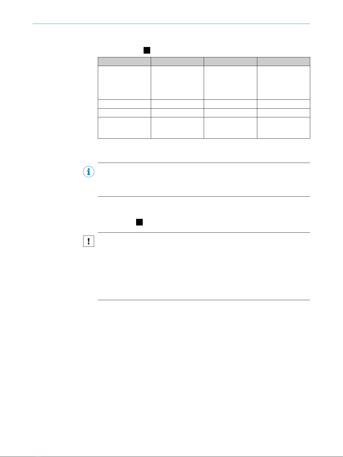
Anzeigen des Senders
Position der LEDs: A
Position LED-Farbe Funktion Beschriftung
1Rot/Gelb/Grün Feldanzeige 1), zeigt
den Zustand des
Schutzfelds und wei‐
tere Informationen zur
Statusanzeige an
–
2– Laser-Ausrichthilfe –
3Rot/Gelb/Grün Statusanzeige STATE
1) Sicherheits-Lichtvorhänge mit Schutzfeldhöhe > 300 mm haben mehrere LEDs für die Feldanzeige.
MONTAGEANLEITUNG
8022020/ZYO3/2018-05-15 | SICK M O N T A G E A N L E I T U N G | deTec4 3
Irrtümer und Änderungen vorbehalten

Anzeigen des Empfängers
Position der LEDs: B
Position LED-Farbe Funktion Beschriftung
1Rot/Gelb/Grün Feldanzeige 1), zeigt
den Zustand des
Schutzfelds und wei‐
tere Informationen zur
Statusanzeige an
–
2Blau/Rot/Gelb/Weiß Diagnose 1, 2, 3, 4, 5, 6, 7, 8
3Rot/Grün OSSD-Zustand OSSD
4Rot/Gelb/Grün Endkappe mit inte‐
griertem Leuchtmel‐
der (optional)
–
1) Sicherheits-Lichtvorhänge mit Schutzfeldhöhe > 300 mm haben mehrere LEDs für die Feldanzeige.
Die Diagnose-LEDs 1 ... 4 zeigen auch die Ausrichtgüte an.
HINWEIS
Wenn die Diagnose-LED 6 weiß leuchtet, ist eine reduzierte Auflösung konfiguriert. Die
wirksame Auflösung muss dann am Gerät und an der Maschine durch geeignete Maß‐
nahmen (z. B. durch eine Beschriftung oder ein Hinweisschild) gekennzeichnet werden.
5 Systemstecker montieren
Systemstecker: C
WICHTIG
Beschädigung des Geräts
Wenn der Systemstecker nicht montiert ist, können Schmutz, Staub oder Feuchtigkeit
in das Gerät eindringen und es beschädigen.
Wenn der Systemstecker nicht montiert ist, können elektrostatische Entladungen an
den Kontakten das Gerät beschädigen.
bDas Eindringen von Schmutz, Staub und Feuchtigkeit verhindern.
bElektrostatische Entladungen an den Kontakten verhindern.
1. Sicherstellen, dass Sicherheits-Lichtvorhang und Systemstecker während der
Montage des Systemsteckers spannungsfrei sind.
2. Systemstecker auspacken.
3. Bei Bedarf DIP-Schalter einstellen, siehe Information auf dem Systemstecker.
4. Schutzfolie vom Anschlussraum des Sicherheits-Lichtvorhangs entfernen.
5. Systemstecker vorsichtig auf den Anschlussraum des Sicherheits-Lichtvorhangs
aufstecken.
6. Systemstecker mit den zwei unverlierbaren Schrauben am Sicherheits-Lichtvor‐
hang festschrauben. Drehmoment 0,5 Nm ± 0,1 Nm.
MONTAGEANLEITUNG
4M O N T A G E A N L E I T U N G | deTec4 8022020/ZYO3/2018-05-15 | SICK
Irrtümer und Änderungen vorbehalten

6 Montieren
GEFAHR
Gefahr der Unwirksamkeit der Schutzeinrichtung
Zu schützende Personen und Körperteile werden bei Nichtbeachtung möglicherweise
nicht erkannt.
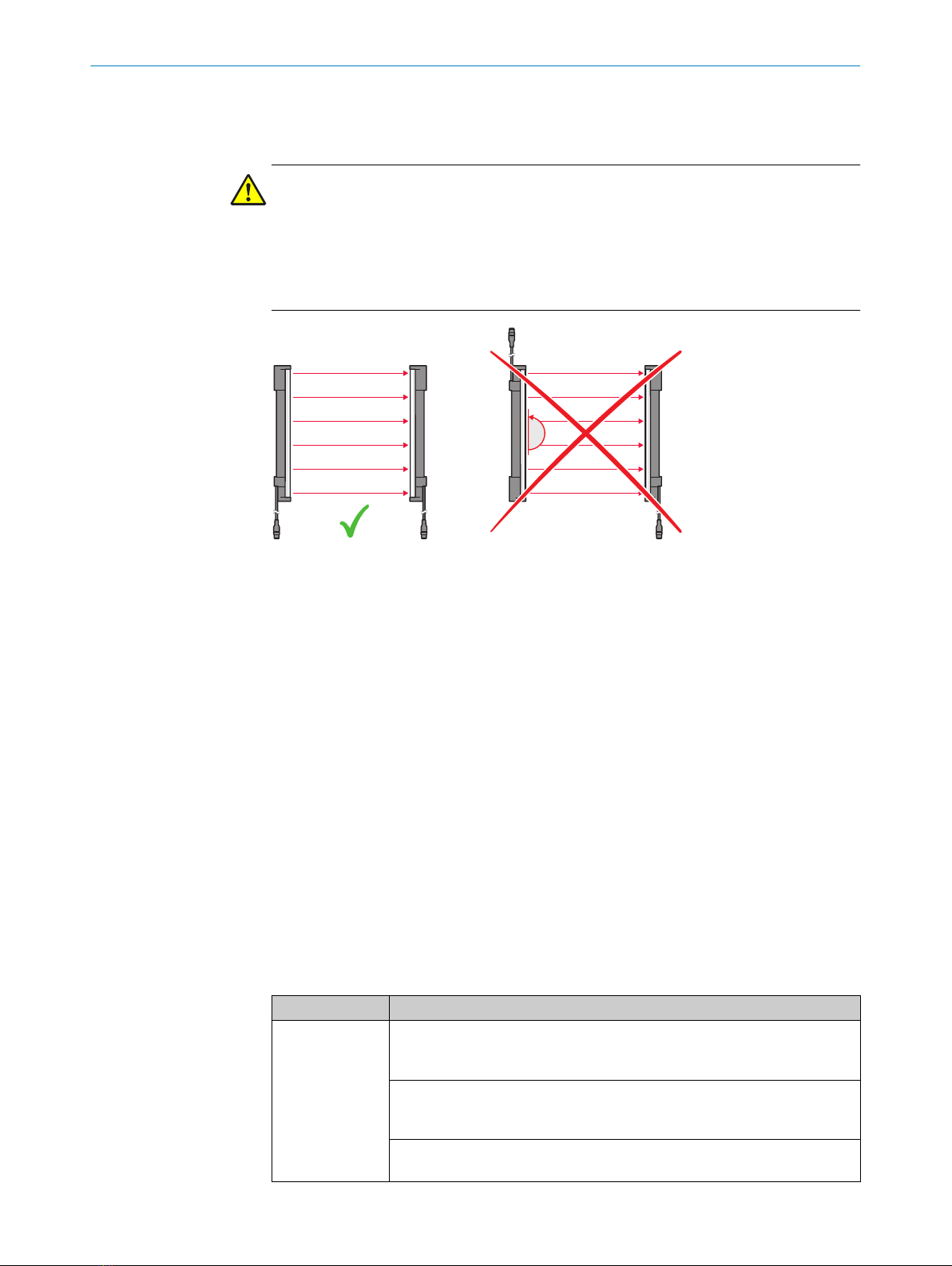
bDas Ende mit dem Leitungsanschluss muss bei Sender und Empfänger in die glei‐
che Richtung zeigen.
180˚
r
sr
s
bSender und Empfänger auf einem planen Untergrund montieren.
bSender und den Empfänger so montieren, dass ein rechteckiges Schutzfeld ent‐
steht, d. h. bei vertikaler Montage auf gleicher Höhe. Für kleinere Korrekturen bei
der Ausrichtung lassen sich Sender und Empfänger in den Haltern in Längsrich‐
tung verschieben.
bDie Halterungen in der Nähe der Gehäuseenden positionieren. Bei Geräten mit
einer Schutzfeldhöhe > 300 mm darf der Abstand zwischen Halterung und Gehäu‐
seende maximal 1/4 der Gehäuselänge betragen. Wenn das Gerät im Betrieb star‐
ken Vibrationen ausgesetzt ist, die Montagehöhe der oberen Halterung so wählen,
dass der Absatz im Gehäuse des Sicherheits-Lichtvorhangs auf der Halterung auf‐
sitzt .
bAnzugsdrehmoment für die Schrauben, mit denen die Halterung montiert wird:
5 Nm ... 6 Nm. Anzugsdrehmoment für die Schrauben, mit denen der Sicherheits-
Lichtvorhang in der Halterung fixiert wird: 2,5 Nm ... 3 Nm. Höhere Drehmomente
können die Halterung beschädigen, geringere Drehmomente bieten keine ausrei‐
chende Sicherheit gegen ein Verschieben des Sicherheits-Lichtvorhangs.
bAuf die korrekte Ausrichtung von Sender und Empfänger achten. Die Optiken von
Sender und Empfänger müssen sich gegenüber liegen.
bParallelität der Komponenten ggf. mit einer Wasserwaage prüfen.
6.1 QuickFix-Halterung montieren
Seitliche und rückseitige Montage der QuickFix-Halterung
Montageart Beschreibung
Seitlich Mit der M5-Schraube durch die QuickFix-Halterung an den Maschinen- oder
Profilrahmen. Am Maschinen- oder Profilrahmen ist eine Schraubenmutter
oder eine Gewindebohrung erforderlich (!).
Mit der M5-Schraube durch den Maschinen- oder Profilrahmen an die
QuickFix-Halterung. Eine Schraubenmutter ist für jede QuickFix-Halterung
erforderlich ( ").
Mit der M5-Schraube durch die QuickFix-Halterung an den Profilrahmen. Am
Profilrahmen ist ein Nutenstein erforderlich (§).
MONTAGEANLEITUNG
8022020/ZYO3/2018-05-15 | SICK M O N T A G E A N L E I T U N G | deTec4 5
Irrtümer und Änderungen vorbehalten

Montageart Beschreibung
Rückseitig Mit der M5-Schraube durch die QuickFix-Halterung an den Maschinen- oder
Profilrahmen. Am Maschinen- oder Profilrahmen ist eine Schraubenmutter
oder eine Gewindebohrung erforderlich ($).
Montage: D
6.2 FlexFix-Halterung montieren
Seitliche und rückseitige Montage der FlexFix-Halterung
Montageart Beschreibung
Seitlich Mit der M5-Schraube durch die FlexFix-Halterung an den Maschinen- oder
Profilrahmen. Am Maschinen- oder Profilrahmen ist eine Schraubenmutter
oder eine Gewindebohrung erforderlich (!).
Mit der M5-Schraube durch die FlexFix-Halterung an den Profilrahmen. Am
Profilrahmen sind 2 Nutensteine erforderlich (").
Rückseitig Mit der M5-Schraube durch die FlexFix-Halterung an den Maschinen- oder
Profilrahmen. Am Maschinen- oder Profilrahmen ist eine Schraubenmutter
oder eine Gewindebohrung erforderlich (§).
1. Nach der Montage der FlexFix-Halterungen Sender bzw. Empfänger von vorn in die
FlexFix-Halterungen eindrehen und Sender und Empfänger ausrichten.
HINWEIS
Das Eindrehen des Sicherheits-Lichtvorhangs ist nur möglich, wenn sich die beiden
FlexFix-Halterungen in einer Flucht befinden.
Empfehlung:
1. Die Schrauben der FlexFix-Halterungen zunächst nur handfest eindrehen.
2. Die beiden FlexFix-Halterungen in eine Flucht bringen. Dazu z. B. ein Richtscheit
oder eine Wasserwaage an die nicht benutzten Anschraubflächen der FlexFix-Hal‐
terungen legen.
3. Schrauben festdrehen.
2. Die Position des Senders und des Empfängers mit der M5-Schraube in der FlexFix-
Halterung fixieren.
Montage: E
7 Anschlussbelegung
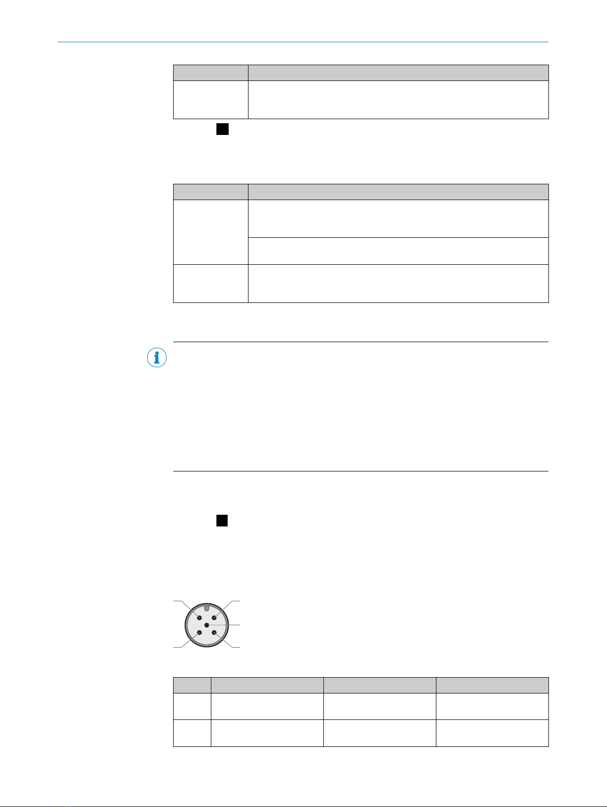
Systemanschluss (M12, 5-polig)
12
34
5
Pinbelegung Systemanschluss (Stecker, M12, 5-polig)
Pin Aderfarbe 1) s Sender r Empfänger
1 Braun +24 V DC (Eingang Span‐
nungsversorgung)
+24 V DC (Eingang Span‐
nungsversorgung)
2 Weiß In2 (Taster Laser-Ausricht‐
hilfe)
OSSD1
MONTAGEANLEITUNG
6M O N T A G E A N L E I T U N G | deTec4 8022020/ZYO3/2018-05-15 | SICK
Irrtümer und Änderungen vorbehalten

Pin Aderfarbe 1) s Sender r Empfänger
3 Blau 0 V DC (Eingang Span‐
nungsversorgung)
0 V DC (Eingang Span‐
nungsversorgung)
4 Schwarz In1 (Schalter Laser-Aus‐
richthilfe / Eingang Kaska‐
densynchronisierung)
OSSD2
5 2) Grau Com1
(Einzelsystem oder Host:
Sender-Empfänger-Kommu‐
nikation
Guest: Kaskadenkommuni‐
kation)
Com1
(Einzelsystem oder Host:
Sender-Empfänger-Kommu‐
nikation
Guest: Kaskadenkommuni‐
kation)
1) Gilt für die als Zubehör empfohlenen Verlängerungsleitungen.
2) Wenn Sender und Empfänger nicht verbunden werden, kann bei einem Einzelsystem oder Host Pin 5
unbelegt bleiben und z. B. eine 4-polige Leitung mit 4-poliger Dose verwendet werden.
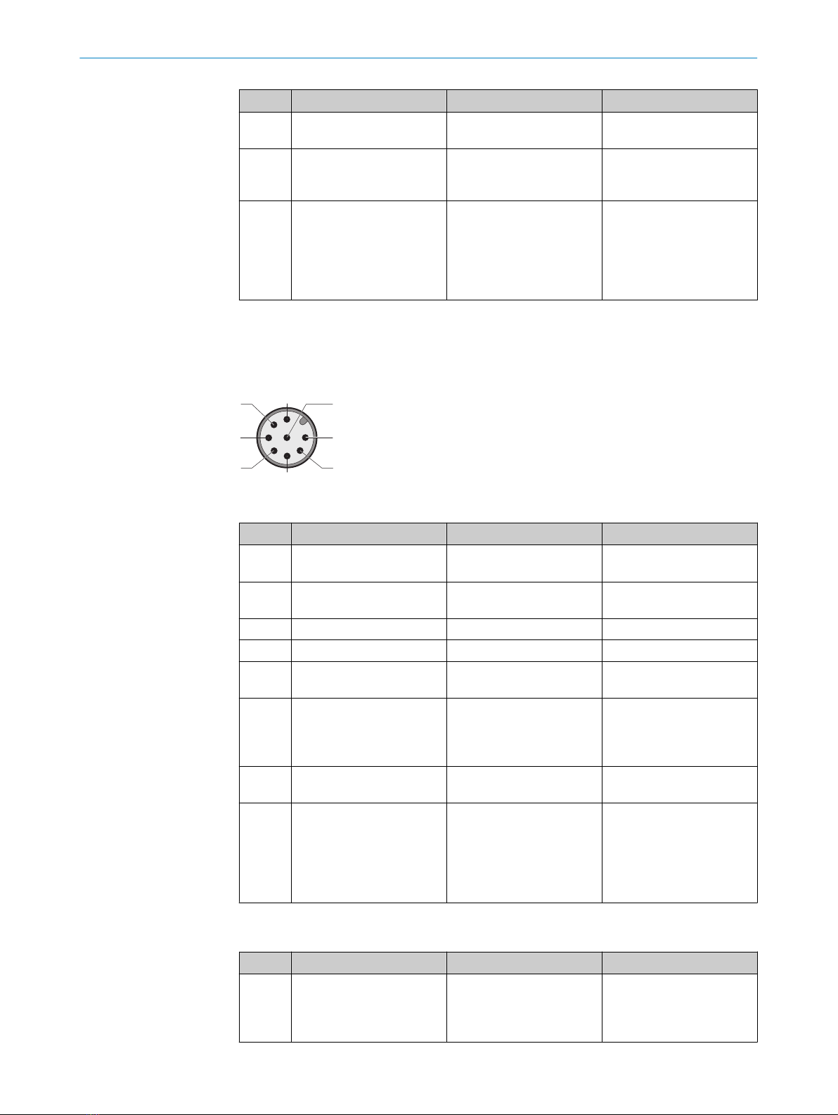
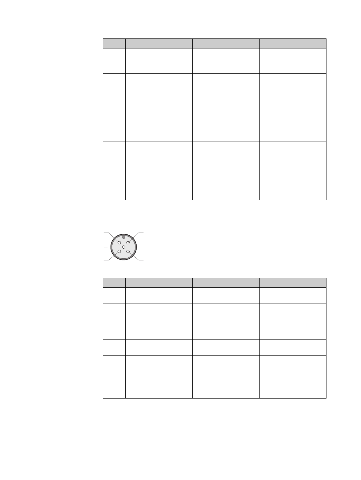
Systemanschluss (M12, 8-polig)
8
2
3
4
57
1
6
Pinbelegung Systemanschluss Systemstecker SP1 (Stecker M12, 8-polig)
Pin Aderfarbe 1) s Sender r Empfänger
1 Weiß Nicht belegt RES (Eingang Rücksetztas‐
ter)
2 Braun +24 V DC (Eingang Span‐
nungsversorgung)
+24 V DC (Eingang Span‐
nungsversorgung)
3 Grün Nicht belegt ADO (Meldeausgang)
4 Gelb Nicht belegt EDM (EDM-Eingang)
5 Grau In2 (Taster Laser-Ausricht‐
hilfe)
OSSD1
6 Rosa In1
(Schalter Laser-Ausricht‐
hilfe/Eingang Kaskaden‐
synchronisierung)
OSSD2
7 Blau 0 V DC (Eingang Span‐
nungsversorgung)
0 V DC (Eingang Span‐
nungsversorgung)
8 Rot Com1
(Einzelsystem oder Host:
Sender-Empfänger-Kommu‐
nikation
Guest: Kaskadenkommuni‐
kation)
Com1
(Einzelsystem oder Host:
Sender-Empfänger-Kommu‐
nikation
Guest: Kaskadenkommuni‐
kation)
1) Gilt für die als Zubehör empfohlenen Verlängerungsleitungen.
Pinbelegung Systemanschluss Systemstecker SP2 (Stecker M12, 8-polig)
Pin Aderfarbe 1) s Sender r Empfänger
1 Weiß Nicht belegt In3
RES (Eingang Rücksetztas‐
ter) oder Override (Eingang
Override)
MONTAGEANLEITUNG
8022020/ZYO3/2018-05-15 | SICK M O N T A G E A N L E I T U N G | deTec4 7
Irrtümer und Änderungen vorbehalten

Pin Aderfarbe 1) s Sender r Empfänger
2 Braun +24 V DC (Eingang Span‐
nungsversorgung)
+24 V DC (Eingang Span‐
nungsversorgung)
3 Grün Nicht belegt ADO (Meldeausgang)
4 Gelb Nicht belegt In4
EDM (EDM-Eingang) oder
Muting-Signal 1
5 Grau In2 (Taster Laser-Ausricht‐
hilfe)
OSSD1
6 Rosa In1
(Schalter Laser-Ausricht‐
hilfe/Eingang Kaskaden‐
synchronisierung)
OSSD2
7 Blau 0 V DC (Eingang Span‐
nungsversorgung)
0 V DC (Eingang Span‐
nungsversorgung)
8 Rot Com1
(Einzelsystem oder Host:
Sender-Empfänger-Kommu‐
nikation
Guest: Kaskadenkommuni‐
kation)
Com1
(Einzelsystem oder Host:
Sender-Empfänger-Kommu‐
nikation
Guest: Kaskadenkommuni‐
kation)
1) Gilt für die als Zubehör empfohlenen Verlängerungsleitungen.
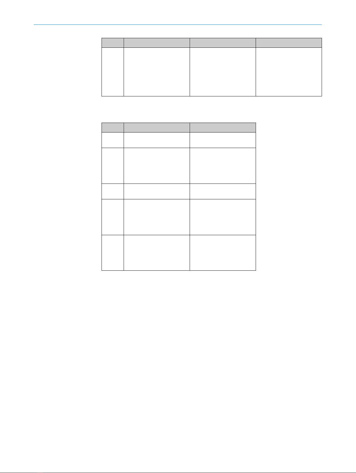
Erweiterungsanschluss (M12, 5-polig)
21
43
5
Pinbelegung Erweiterungsanschluss Systemstecker SP1 (Dose M12, 5-polig)
Pin Aderfarbe 1) s Sender r Empfänger
1 Braun 24 V Out (Ausgang Span‐
nungsversorgung) 2)
24 V Out (Ausgang Span‐
nungsversorgung) 2)
2 Weiß Nicht belegt In1
(Einzelsystem oder letzter
Guest: EDM [EDM-Eingang]
Host oder erster von 2
Guests: Eingang OSSD)
3 Blau 0 V Out (Ausgang Span‐
nungsversorgung)
0 V Out (Ausgang Span‐
nungsversorgung)
4 Schwarz Sync-Out (Ausgang Kaska‐
densynchronisierung)
In2
(Einzelsystem oder letzter
Guest: RES [Eingang Rück‐
setztaster]
Host oder erster von 2
Guests: Eingang OSSD)
MONTAGEANLEITUNG
8M O N T A G E A N L E I T U N G | deTec4 8022020/ZYO3/2018-05-15 | SICK
Irrtümer und Änderungen vorbehalten

Pin Aderfarbe 1) s Sender r Empfänger
5 Grau Com2 (Kaskadenkommuni‐
kation)
Com2
(Einzelsystem oder letzter
Guest: ADO [Meldeaus‐
gang] / IO-Link
Host oder erster von 2
Guests: Kaskadenkommu‐
nikation)
1) Gilt für die als Zubehör empfohlenen Verlängerungsleitungen.
2) Nur zur Kaskadierung von deTec-Geräten und nicht zum Anschluss anderer Geräte geeignet.
Pinbelegung Erweiterungsanschluss Systemstecker SP2 (Dose M12, 5-polig)
Pin Aderfarbe 1) r Empfänger
1 Braun 24 V Out (Ausgang Span‐
nungsversorgung) 2)
2 Weiß In1
(Einzelsystem: EDM [EDM-
Eingang] 3) / Muting-Signal
1
Host: Eingang OSSD)
3 Blau 0 V Out (Ausgang Span‐
nungsversorgung)
4 Schwarz In2
(Einzelsystem: RES [Ein‐
gang Rücksetztaster] /
Muting-Signal 2
Host: Eingang OSSD)
5 Grau Com2
(Einzelsystem: ADO [Melde‐
ausgang] / IO-Link
Host: Kaskadenkommuni‐
kation)
1) Gilt für die als Zubehör empfohlenen Verlängerungsleitungen.
2) Nur zur Kaskadierung von deTec-Geräten und nicht zum Anschluss anderer Geräte geeignet.
3) Wenn Muting konfiguriert ist, ist EDM am Erweiterungsanschluss nicht möglich.
bBei Kaskade: Erweiterungsanschluss des Host mit Systemanschluss von Guest 1
verbinden
bBei Kaskade mit zwei Guest-Geräten: Zusätzlich Erweiterungsanschluss von Guest
1 mit Systemanschluss von Guest 2 verbinden.
MONTAGEANLEITUNG
8022020/ZYO3/2018-05-15 | SICK M O N T A G E A N L E I T U N G | deTec4 9
Irrtümer und Änderungen vorbehalten

A
!
"
§
B
!
§
$
"
1234
5 6 7 8
C
D
!
§
$
"
a
b
a
b
E
!
"
§
MONTAGEANLEITUNG
10 M O N T A G E A N L E I T U N G | deTec4 8022020/ZYO3/2018-05-15 | SICK
Irrtümer und Änderungen vorbehalten

All rights reserved. Subject to change without notice.
1 About this document
This document applies to the deTec4 safety light curtain.
2 Safety information
DANGER
Hazard due to lack of effectiveness of the protective device
In the case of non-compliance, it is possible that the dangerous state of the machine
may not be stopped or not stopped in a timely manner.
bPlease observe the safety notes provided.
The safety light curtain is not suitable for the following applications, among others:
•Outdoors
•Underwater
•In explosion-hazardous areas
•At altitudes over 3,000 m above sea level
•In environments with enhanced ionizing radiation
A fuse rated maximum 2 A shall be installed in the isolated 24 V DC power supply cir‐
cuit to the device in order to limit the available current.
For more information about how to work with the protective device, refer to the machin‐
ery documentation or the operating instructions for the protective device. You can call
up the EU declaration of conformity and the current operating instructions for the pro‐
tective device by entering the part number in the search field at www.sick.com (part
number: see the type label entry in the “Ident. no.” field).
3 Sender and receiver
sThe symbol indicates the sender.
rThe symbol indicates the receiver.
4 Status indicators
Complete overview of the LED statuses and their meanings: see operating instructions.
Sender indicators
Position of LEDs: A
Position LED color Function Labeling
1Red/yellow/green Field indicator 1);
shows the status of
the protective field
and additional infor‐
mation about the sta‐
tus display
–
2– Laser alignment aid –
3Red/yellow/green Status indicator STATE
1) Safety light curtains with protective field height > 300 mm have several light emitting diodes for the field
indicator.
MOUNTING INSTRUCTIONS
12 M O U N T I N G I N S T R U C T I O N S | deTec4 8022020/ZYO3/2018-05-15 | SICK
Subject to change without notice

Receiver indicators
Position of LEDs: B
Position LED color Function Labeling
1Red/yellow/green Field indicator 1);
shows the status of
the protective field
and additional infor‐
mation about the sta‐
tus display
–
2Blue/red/yellow/white Diagnostics 1, 2, 3, 4, 5, 6, 7, 8
3Red/green OSSD status OSSD
4Red/yellow/green End cap with inte‐
grated LED (optional)
–
1) Safety light curtains with protective field height > 300 mm have several light emitting diodes for the field
indicator.
Diagnostic LEDs 1 to 4 also display the alignment quality.
NOTE
If diagnostic LED 6 lights up white, reduced resolution has been configured. The effec‐
tive resolution must then be marked on the device and on the machine by taking suit‐
able measures (e.g. a mark or an information label).
5 Mounting the system plug
System plug: C
NOTICE
Damage to the device
If the system plug is not mounted, dirt, dust, or moisture may enter the device and
cause damage.
If the system plug is not mounted, electrostatic discharge at the contacts may damage
the device.
bPrevent the entry of dirt, dust, and moisture.
bPrevent electrostatic discharge at the contacts.
1. Make sure that the safety light curtain and system plug are disconnected from the
power supply while the system plug is being mounted.
2. Unpack the system plug.
3. If necessary, set the DIP switch, see information on the system plug.
4. Remove the protective film from the terminal compartment of the safety light cur‐
tain.
5. Carefully mount the system plug on the terminal compartment of the safety light
curtain.
6. Use the two captive screws to screw the system plug onto the safety light curtain.
Torque 0.5 Nm ± 0.1 Nm.
MOUNTING INSTRUCTIONS
8022020/ZYO3/2018-05-15 | SICK M O U N T I N G I N S T R U C T I O N S | deTec4 13
Subject to change without notice

6 Mounting
DANGER
Hazard due to lack of effectiveness of the protective device
Persons and parts of the body to be protected may not be recognized in case of non-
observance.
bThe end with the cable connection must point in the same direction for the sender
and receiver.
180˚
r
sr
s
bMount the sender and receiver on a level surface.
bMount the sender and receiver such that a right-angled protective field is estab‐
lished, i.e. when mounted vertically at the same height. For minor adjustments
when aligning, the sender and receiver can be adjusted longitudinally in the brack‐
ets.
bPosition the brackets near the ends of the housing. For devices with a protective
field height > 300 mm, the distance between the bracket and the end of the hous‐
ing must not exceed 1/4 of the length of the housing. If the device is exposed to
strong vibrations during operation, mount the top bracket at a height where the
offset in the safety light curtain housing rests on the bracket.
bTightening torque for the screws used to mount the bracket: 5 Nm to 6 Nm. Tight‐
ening torque for the screws used to secure the safety light curtain in the bracket:
2.5 Nm to 3 Nm. Higher torques can damage the bracket, while lower torques are
not secure enough to prevent the safety light curtain from moving.
bMake sure that the sender and receiver are aligned correctly. The optical lens sys‐
tems of the sender and the receiver must be located opposite one another.
bIf necessary, use a spirit level to check that the components are parallel.
6.1 Mounting the QuickFix bracket
Lateral and rear mounting with the QuickFix bracket
Mounting type Description
On the side Fasten the M5 screw to the machine or profile frame through the QuickFix
bracket. A screw nut or threaded hole is required on the machine or profile
frame (!).
Fasten the M5 screw to the QuickFix bracket through the machine or profile
frame. A screw nut is required for each QuickFix bracket ( ").
Fasten the M5 screw to the profile frame through the QuickFix bracket. A
sliding nut is required on the profile frame (§).
On the back Fasten the M5 screw to the machine or profile frame through the QuickFix
bracket. A screw nut or threaded hole is required on the machine or profile
frame ($).
MOUNTING INSTRUCTIONS
14 M O U N T I N G I N S T R U C T I O N S | deTec4 8022020/ZYO3/2018-05-15 | SICK
Subject to change without notice

Mounting: D
6.2 Mounting the FlexFix bracket
Lateral and rear mounting with the FlexFix bracket
Mounting type Description
On the side With the M5 screw through the FlexFix bracket on the machine or profile
frame. A screw nut or threaded hole is required on the machine or profile
frame (!).
With the M5 screw through the FlexFix bracket on the profile frame. Two slid‐
ing nuts are required on the profile frame (").
On the back With the M5 screw through the FlexFix bracket on the machine or profile
frame. A screw nut or threaded hole is required on the machine or profile
frame (§).
1. After mounting the FlexFix brackets, screw the sender and receiver into the FlexFix
brackets from the front and align the sender and receiver.
NOTE
The safety light curtain can only be screwed in when both FlexFix brackets are in align‐
ment.
Recommendation:
1. Only hand-tighten the screws on the FlexFix brackets at first.
2. Align the two FlexFix brackets. To do this, place a straightedge or spirit level, for
example, at the screw mounting surfaces of the FlexFix brackets that are not being
used.
3. Tighten the screws.
2. Use an M5 screw to fix the position of the sender and receiver in the FlexFix
bracket.
Mounting: E
7 Pin assignment
System connection (M12, 5-pin)
12
34
5
System connection pin assignment (male connector, M12, 5-pin)
Pin Wire color 1) s Sender r Receiver
1 Brown +24 V DC (voltage supply
input)
+24 V DC (voltage supply
input)
2 White In2 (laser alignment aid
button)
OSSD1
3 Blue 0 V DC (voltage supply
input)
0 V DC (voltage supply
input)
4 Black In1 (laser alignment aid
switch/cascade synchro‐
nization input)
OSSD2
MOUNTING INSTRUCTIONS
8022020/ZYO3/2018-05-15 | SICK M O U N T I N G I N S T R U C T I O N S | deTec4 15
Subject to change without notice

Pin Wire color 1) s Sender r Receiver
5 2) Gray Com1
(Single system or host:
sender/receiver communi‐
cation
Guest: cascade communi‐
cation)
Com1
(Single system or host:
sender/receiver communi‐
cation
Guest: cascade communi‐
cation)
1) Applies to the extension cables recommended as accessories.
2) If the sender and the receiver are not connected, pin 5 can remain unassigned for a single system or
host and, for example, a 4-pin cable with a 4-pin female connector can be used.
System connection (M12, 8-pin)
8
2
3
4
57
1
6
SP1 system plug system connection pin assignment (M12 male connector, 8-pin)
Pin Wire color 1) s Sender r Receiver
1 White Not assigned RES (reset pushbutton
input)
2 Brown +24 V DC (voltage supply
input)
+24 V DC (voltage supply
input)
3 Green Not assigned ADO (application diagnostic
output)
4 Yellow Not assigned EDM (EDM input)
5 Gray In2 (laser alignment aid
button)
OSSD1
6 Pink In1
(laser alignment aid
switch/cascade synchro‐
nization input)
OSSD2
7 Blue 0 V DC (voltage supply
input)
0 V DC (voltage supply
input)
8 Red Com1
(Single system or host:
sender/receiver communi‐
cation
Guest: cascade communi‐
cation)
Com1
(Single system or host:
sender/receiver communi‐
cation
Guest: cascade communi‐
cation)
1) Applies to the extension cables recommended as accessories.
SP2 system plug system connection pin assignment (M12 male connector, 8-pin)
Pin Wire color 1) s Sender r Receiver
1 White Not assigned In3
RES (reset pushbutton
input) or override (override
input)
2 Brown +24 V DC (voltage supply
input)
+24 V DC (voltage supply
input)
3 Green Not assigned ADO (application diagnostic
output)
MOUNTING INSTRUCTIONS
16 M O U N T I N G I N S T R U C T I O N S | deTec4 8022020/ZYO3/2018-05-15 | SICK
Subject to change without notice

Pin Wire color 1) s Sender r Receiver
4 Yellow Not assigned In4
EDM (EDM input) or muting
signal 1
5 Gray In2 (laser alignment aid
button)
OSSD1
6 Pink In1
(laser alignment aid
switch/cascade synchro‐
nization input)
OSSD2
7 Blue 0 V DC (voltage supply
input)
0 V DC (voltage supply
input)
8 Red Com1
(Single system or host:
sender/receiver communi‐
cation
Guest: cascade communi‐
cation)
Com1
(Single system or host:
sender/receiver communi‐
cation
Guest: cascade communi‐
cation)
1) Applies to the extension cables recommended as accessories.
Extension connection (M12, 5-pin)
21
43
5
SP1 system plug extension connection pin assignment (M12 female connector, 5-pin)
Pin Wire color 1) s Sender r Receiver
1 Brown 24 V Out (voltage supply
output) 2)
24 V Out (voltage supply
output) 2)
2 White Not assigned In1
(Single system or last
guest: EDM [EDM input]
Host or first of 2 guests:
OSSD input)
3 Blue 0 V Out (voltage supply out‐
put)
0 V Out (voltage supply out‐
put)
4 Black Sync-Out (cascade synchro‐
nization output)
In2
(Single system or last
guest: RES [reset pushbut‐
ton input]
Host or first of 2 guests:
OSSD input)
5 Gray Com2 (cascade communi‐
cation)
Com2
(Single system or last
guest: ADO [application
diagnostic output] / IO-Link
Host or first of 2 guests:
cascade communication)
1) Applies to the extension cables recommended as accessories.
2) Only for cascading deTec devices, not suitable for connecting other devices.
MOUNTING INSTRUCTIONS
8022020/ZYO3/2018-05-15 | SICK M O U N T I N G I N S T R U C T I O N S | deTec4 17
Subject to change without notice

SP2 system plug extension connection pin assignment (M12 female connector, 5-pin)
Pin Wire color 1) r Receiver
1 Brown 24 V Out (voltage supply
output) 2)
2 White In1
(Single system: EDM [EDM
input] 3) / muting signal 1
Host: OSSD input)
3 Blue 0 V Out (voltage supply out‐
put)
4 Black In2
(Single system: RES [reset
pushbutton input] / muting
signal 2
Host: OSSD input)
5 Gray Com2
(Single system: ADO [appli‐
cation diagnostic output] /
IO-Link
Host: cascade communica‐
tion)
1) Applies to the extension cables recommended as accessories.
2) Only for cascading deTec devices, not suitable for connecting other devices.
3) When muting is configured, EDM is not possible at the extension connection.
bFor cascading: connect the extension connection of the host to the system con‐
nection of guest 1.
bFor cascading with two guest devices: connect additional extension connection of
guest 1 to the system connection of guest 2.
A
!
"
§
B
!
§
$
"
1234
5 6 7 8
C
MOUNTING INSTRUCTIONS
18 M O U N T I N G I N S T R U C T I O N S | deTec4 8022020/ZYO3/2018-05-15 | SICK
Subject to change without notice

D
!
§
$
"
a
b
a
b
E
!
"
§
MOUNTING INSTRUCTIONS
8022020/ZYO3/2018-05-15 | SICK M O U N T I N G I N S T R U C T I O N S | deTec4 19
Subject to change without notice

Further locations at www.sick.com
Australia
Phone +61 (3) 9457 0600
1800 33 48 02 – tollfree
E-Mail [email protected]
Austria
Phone +43 (0) 2236 62288-0
E-Mail [email protected]
Belgium/Luxembourg
Phone +32 (0) 2 466 55 66
E-Mail info@sick.be
Brazil
Phone +55 11 3215-4900
E-Mail [email protected]
Canada
Phone +1 905.771.1444
E-Mail [email protected]
Czech Republic
Phone +420 2 57 91 18 50
E-Mail [email protected]
Chile
Phone +56 (2) 2274 7430
E-Mail [email protected]
China
Phone +86 20 2882 3600
E-Mail info[email protected]
Denmark
Phone +45 45 82 64 00
E-Mail [email protected]
Finland
Phone +358-9-25 15 800
E-Mail [email protected]
France
Phone +33 1 64 62 35 00
E-Mail info@sick.fr
Germany
Phone +49 (0) 2 11 53 01
E-Mail info@sick.de
Hong Kong
Phone +852 2153 6300
E-Mail [email protected]
Hungary
Phone +36 1 371 2680
E-Mail ertek[email protected]
India
Phone +91-22-6119 8900
E-Mail info@sick-india.com
Israel
Phone +972-4-6881000
E-Mail info@sick-sensors.com
Italy
Phone +39 02 27 43 41
E-Mail info@sick.it
Japan
Phone +81 3 5309 2112
E-Mail [email protected]
Malaysia
Phone +603-8080 7425
E-Mail enquiry[email protected]
Mexico
Phone +52 (472) 748 9451
E-Mail mario.gar[email protected]
Netherlands
Phone +31 (0) 30 229 25 44
E-Mail info@sick.nl
New Zealand
Phone +64 9 415 0459
0800 222 278 – tollfree
E-Mail [email protected]z
Norway
Phone +47 67 81 50 00
E-Mail [email protected]
Poland
Phone +48 22 539 41 00
E-Mail info@sick.pl
Romania
Phone +40 356-17 11 20
E-Mail [email protected]
Russia
Phone +7 495 283 09 90
E-Mail info@sick.ru
Singapore
Phone +65 6744 3732
E-Mail [email protected]
Slovakia
Phone +421 482 901 201
E-Mail mail@sick-sk.sk
Slovenia
Phone +386 591 78849
E-Mail [email protected]
South Africa
Phone +27 (0)11 472 3733
E-Mail info@sickautomation.co.za
South Korea
Phone +82 2 786 6321
E-Mail info@sickkorea.net
Spain
Phone +34 93 480 31 00
E-Mail info@sick.es
Sweden
Phone +46 10 110 10 00
E-Mail info@sick.se
Switzerland
Phone +41 41 619 29 39
E-Mail [email protected]
Taiwan
Phone +886-2-2375-6288
E-Mail [email protected]
Thailand
Phone +66 2 645 0009
E-Mail marcom.th@sick.com
Turkey
Phone +90 (216) 528 50 00
E-Mail info@sick.com.tr
United Arab Emirates
Phone +971 (0) 4 88 65 878
E-Mail info@sick.ae
United Kingdom
Phone +44 (0)17278 31121
E-Mail info@sick.co.uk
USA
Phone +1 800.325.7425
E-Mail info@sick.com
Vietnam
Phone +65 6744 3732
E-Mail [email protected]
SICK AG | Waldkirch | Germany | www.sick.com
8022020/ZYO3/2018-05-15/de, en
Other manuals for deTec4 Core
16
Table of contents
Languages:
Other SICK Accessories manuals

SICK
SICK DT50-2 Pro User manual

SICK
SICK GL6L Series User manual

SICK
SICK NAV210 User manual

SICK
SICK WT18-3 User manual

SICK
SICK Dx35 User manual

SICK
SICK CQF16 User manual

SICK
SICK PowerProx Micro WTT2SL Series User manual

SICK
SICK RMS3 Series User manual

SICK
SICK MZT6-03VPS-KPX User manual

SICK
SICK TiM8 DistanceGuard Series User manual