Planer BT37 MarkII User manual

®
BT37 MarkII
Model No: BT37-02
Service Manual
© 2021 Planer Limited
Original Instructions
MA200606 1.0.0


3
BT37 MarkII: Service Manual MA200606 1.0.0
Table of contents
1. Introduction 7
1.1 About the equipment .................................................................................................... 8
1.1.1 Theory of operation .................................................................................................. 8
1.1.2 Front view ................................................................................................................. 9
1.1.3 Side view .................................................................................................................. 9
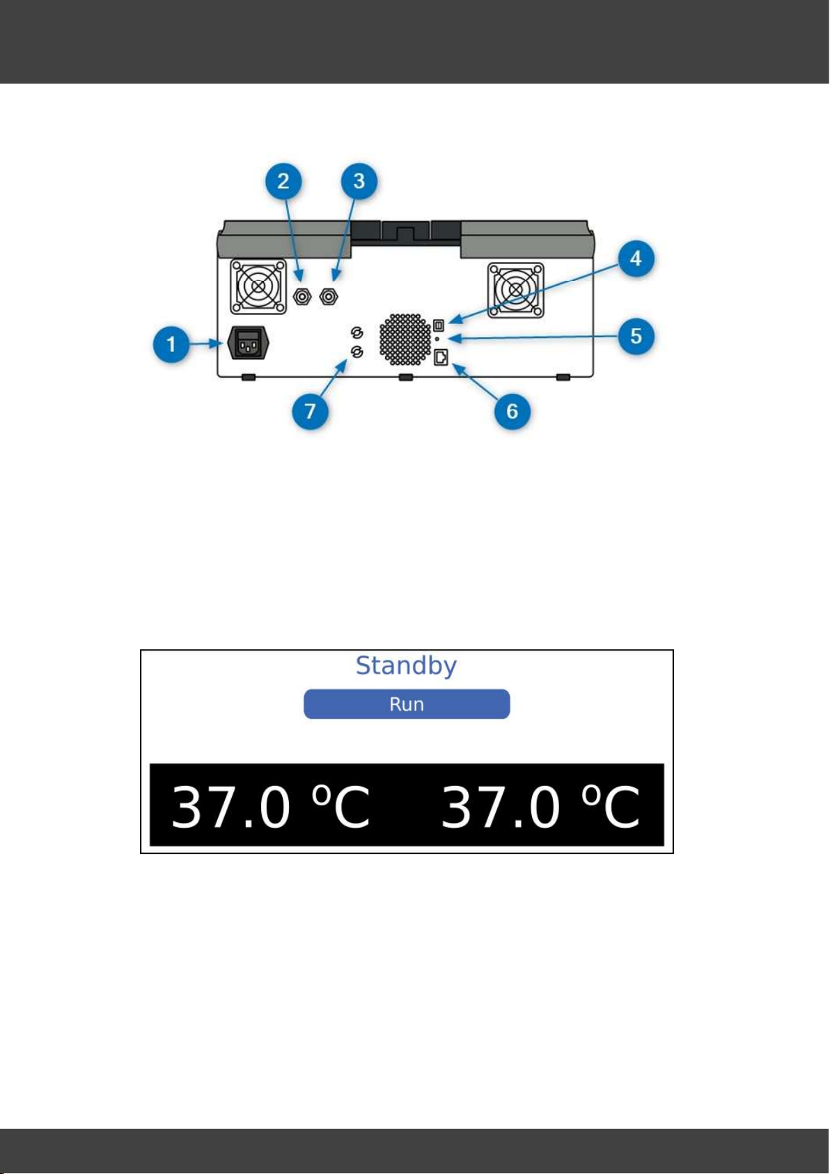
1.1.4 Rear view ................................................................................................................ 10
1.1.5 User interface ......................................................................................................... 10
1.1.5.1 Numeric entry .......................................................................................................................................... 11
1.1.5.2 Menus ....................................................................................................................................................... 12
1.1.6 Status and alarm indicators ................................................................................... 12
1.1.6.1 Acknowledging an alarm ...................................................................................................................... 13
1.2 Intended use ................................................................................................................. 13
1.3 Safety ............................................................................................................................ 13
1.3.1 Warnings ................................................................................................................ 13
1.3.2 Precautions ............................................................................................................. 14
1.3.3 Electromagnetic compatibility (EMC) precautions ................................................ 14
1.4 Symbols ......................................................................................................................... 15
1.4.1 Symbols used in manual ......................................................................................... 15
1.4.2 Symbols used on equipment .................................................................................. 15
1.5 Equipment list .............................................................................................................. 16
1.6 Spare parts ................................................................................................................... 16
1.7 Changing the IP address .............................................................................................. 17
2. Operation 21
2.1 Setting the access code ............................................................................................... 22
2.2 Changing the control settings ..................................................................................... 23
2.2.1 Gas flow ................................................................................................................. 23
2.2.1.1 Non-pulsed bleed flow .......................................................................................................................... 24
2.2.1.2 Pulsed bleed flow ................................................................................................................................... 24
2.3 Installing the humidifier .............................................................................................. 24
2.3.1 Single tube bottle humidifier .................................................................................. 26
2.3.2 Three tube bottle humidifier .................................................................................. 30
2.4 Switching off ................................................................................................................ 34
3. Component replacement 35
3.1 Opening the BT37 ........................................................................................................ 36
3.2 Lid seal .......................................................................................................................... 39
3.3 Upper heater ribbon cable .......................................................................................... 40
3.4 External air filter .......................................................................................................... 46
3.5 Internal air filter ........................................................................................................... 47
3.6 Fan ................................................................................................................................. 48

4
BT37 MarkII: Service Manual MA200606 1.0.0
Table of contents
3.7 Fuse ............................................................................................................................... 49
3.8 Gas valve replacement ................................................................................................ 51
3.9 Battery .......................................................................................................................... 53
3.10 Humidifier ..................................................................................................................... 54
3.11 Left humidifier pcb ...................................................................................................... 56
3.12 Right humidifier pcb .................................................................................................... 57
3.13 Lower heater plate ...................................................................................................... 58
3.14 Upper heater plate ...................................................................................................... 62
3.15 Mains inlet filter ........................................................................................................... 67
3.16 Motherboard ................................................................................................................ 71
3.17 Display ........................................................................................................................... 75
3.18 Power supply ................................................................................................................ 76
3.19 Hinge adjustment ......................................................................................................... 82
3.20 Presetting rotary damper ........................................................................................... 85
4. Maintenance and trouble shooting 89
4.1 Fault finding ................................................................................................................. 90
4.2 Gas leak test ................................................................................................................. 97
4.3 Maintenance schedules ............................................................................................... 99
4.3.1 12 months ............................................................................................................... 99
4.3.2 Three year ............................................................................................................ 101
4.3.3 Seven year ............................................................................................................ 101
5. Condensation 103
6. Programming the BT37 MarkII 105
7. Regular checks 109
8. General cleaning 111
9. Resetting the access code 113
10. Cleaning and disinfecting the chamber 115
11. Checking the liquid level indicator 117
12. Checking the battery 119
13. Calibration and servicing 121
14. Safety testing 123
15. Testing the alarms 125

5
BT37 MarkII: Service Manual MA200606 1.0.0
Table of contents
16. Flow calibration 127
17. Temperature calibration 129
18. Configuring BT37 toolbox for automatic calibration 131
19. Calibration using automatic calibration kit 135
20. Configuring BT37 toolbox for manual calibration 149
21. Manual calibration 153
22. Diagrams and schematics 163
22.1 Pneumatic block diagram ......................................................................................... 165
22.2 BT37 MarkII exploded diagram ................................................................................. 166
23. Additional information 167
23.1 External alarm connection ........................................................................................ 168
23.2 Network security ....................................................................................................... 168
23.3 Specification ............................................................................................................... 169
23.3.1 Control .................................................................................................................. 169
23.3.2 Capacity ................................................................................................................ 169
23.3.2.1 Power ...................................................................................................................................................... 169
23.3.2.1.1 Internal battery .............................................................................................................................. 169
23.3.3 Humidifier bottle and filter .................................................................................. 170
23.3.4 Gas supply ............................................................................................................ 170
23.3.5 External alarm connections .................................................................................. 171
23.3.6 Monitoring ............................................................................................................ 171
23.3.7 Fuses .................................................................................................................... 171
23.4 System ......................................................................................................................... 172
173
Index


Introduction

8
BT37 MarkII: Service Manual MA200606 1.0.0
Introduction
1 Introduction
1.1 About the equipment
1.1.1 Theory of operation
The basic principle of operation is illustrated in the diagram below.
Samples are placed in dishes in the left and right chambers which are heated to
maintain a constant temperature. Pre-mixed gas is supplied from a pressurised cylinder,
bubbled through water contained in the humidifier bottle, and then passed to the left and
right chambers. This results in the samples being maintained at a controlled temperature
and within a controlled atmosphere.
If the lids are opened and then shut again, gas is provided at an increased flow rate to
reduce the time taken to restore the chambers back to the required gas concentration.
The BT37 can be in one of three modes: Standby, Run and Bottle change.
Mode Heaters Gas Note
Standby Off Off The system is
inactive and ready to
be switched off.
Bottle change On Off The system is
waiting for the
humidifier to be
changed.
Run Controlled Controlled This is the normal
operating state.

9
BT37 MarkII: Service Manual MA200606 1.0.0
Introduction
1.1.2 Front view
1. Chamber lid and catch.
2. Humidifier lid.
3. Status indicators.
4. Touchscreen display.
5. Liquid level indicator.
The lids are fitted with rotary catches.
1. To open a lid, rotate the knob anticlockwise and lift the lid.
2. To close a lid, rotate the knob so it can engage with the pin on the main body, then
gently lower the lid, and when it is fully closed, rotate the knob clockwise until it is
felt to latch.
The BT37 will not regard a lid as being shut until it is both closed and the knob rotated
clockwise into its locked position.
1.1.3 Side view
1. Rear of base monitoring port for independent temperature probes.
2. Lid monitoring port for independent temperature probes.
3. Front of base monitoring port for independent temperature probes.

10
BT37 MarkII: Service Manual MA200606 1.0.0
Introduction
1.1.4 Rear view
1. Mains inlet.
2. Premixed gas inlet
3. Daisy-chain gas outlet
4. Alarm output.
5. Reset switch.
6. Ethernet output.
7. Access ports for pH monitoring; for use by service personnel only.
1.1.5 User interface
The BT37 is provided with a resistive touchscreen interface.
When the system is idle, the standby screen is shown.
Pressing the Run button, moves the BT37 out of standby and into its normal operating
mode.
In normal operation, the display shows the current status of the incubator. Pressing the
Display button cycles through different screens, each of which shows different
information about the state of incubator. An example is shown below.

11
BT37 MarkII: Service Manual MA200606 1.0.0
Introduction
1. Left-hand chamber readings are shown on the left of the display
2. Humidification chamber readings are shown in the middle of the display.
3. Right-hand chamber readings are shown on the right of the display
4. Lid temperatures are shown at the top of the display above the humidification
chamber readings.
5. Base temperatures are shown at the bottom of the display below the humidification
chamber readings.
6. The current temperature readings are identified by the label CURRENT. If the
setpoints are displayed, the values are displayed in a yellow font and identified by th
e
label SETPOINT.
Other options can be found by selecting the MENU option, which will open the main
menu shown below.
To return to the main display, select Display mode.
All menus operate in the same way, with a set of options and UP and DOWN buttons
which can be used to scroll up and down if there are more options to display.
Sub-menus also contain a BACK button which will take you back to the previous menu.
1.1.5.1 Numeric entry
Some screens require a numeric entry to be entered. At these screens a keypad
appropriate to the required entry will be displayed. The screen for an access code entry
is shown below.

12
BT37 MarkII: Service Manual MA200606 1.0.0
Introduction
1. Use the keypad to enter the required number.
2. Use DEL to erase an invalid entry.
3. Press OK to submit the entry or CANCEL to exit the menu option.
1.1.5.2 Menus
All menu options are shown below:
Display mode: Press to toggle through different presentations of the current incubator
readings and setpoints.
Change bottle: Select to change the humidifier. See the Installing the humidifier
section.
Configuration: Select to change the control settings or calibration settings. Calibration
settings should only be adjusted by trained service personnel.
oControl settings: Select to adjust the main incubator settings. See the Changing the
control settings section.
oCalibration offsets: Select to adjust the calibration settings. Calibration settings
should only be adjusted by trained service personnel. See the Calibration and
servicing section.
Test: Select to run the in-built tests. See the Testing the alarms section.
Set access code: Select to set the access code. See the Setting the access code
section.
Reset access code: Select to reset the access code if it has been forgotten. See the
Resetting the access code section.
Security: Select to allow the incubator settings to be temporarily modified via the
network. See the Network security section.
Standby: Select to place the incubator into standby mode. See the Theory of
operation and Switching off sections.
1.1.6 Status and alarm indicators
The status indicators on the front of the BT37 show the current state of the system.
These are used along with an internal buzzer and the external alarm. The state of the
indicators, buzzer and external alarm in various states are shown below.
24
23
122
126
22
114
168
8 34

13
BT37 MarkII: Service Manual MA200606 1.0.0
Introduction
State Status
indicators
Buzzer External
alarm
Display
Standby Steady orange Off Off Standby
Normal Steady green Off Off Normal display
Unacknowledged
alarm
Flashing red On Off Alarm message
Unacknowledged
alarm for longer than
5 minutes
Flashing red On On Alarm message
Acknowledged alarm Steady red Off Off Normal display
Temperatures not
ready.
Steady orange Off Off Normal display
1.1.6.1 Acknowledging an alarm
When an alarm occurs, an alarm message is shown. An example is shown below:
1. To silence the alarm, press SILENCE.
2. To acknowledge the alarm, press OK. This will close the alarm message.
1.2 Intended use
The BT37 has been designed as a general purpose bench-top incubator. To be used to
provide an environment with controlled temperature at or near body temperature, carbon
dioxide, oxygen and nitrogen gases and elevated humidity.
1.3 Safety
1.3.1 Warnings
Operating the equipment in a manner not specified within this manual or under
conditions outside of the equipment specifications, may result in the protection offered
by the equipment being impaired.
Use in well ventilated areas. Risk of asphyxiation from carbon dioxide released from
the equipment. Additional ventilation may be required. Consider carbon dioxide alarms
in confined spaces. Refer to the Gas supply topic for gas release rates.
170

14
BT37 MarkII: Service Manual MA200606 1.0.0
Introduction
Never connect to flammable or oxidising gas mixtures.
Do not connect to a gas supply with a pressure exceeding 1.65 bar.
Take care when handling samples. Samples may present other biological hazards.
Refer to the person responsible for the equipment.
Do not attempt to charge the battery externally. The BT37 contains a sealed lead acid
battery. Over-charging can result in the release of dangerous gases. Refer to the
Internal battery topic for details.
Equipment must be earthed. Class 1.
Supply power via a residual current circuit breaker (RCCB) operating at a differential of
30 mA.
To avoid risk of fire, fuses must always be replaced with the same type and rating.
oFuses should only be replaced by suitably trained service personnel.
oFuses should only be replaced after the cause of the original failure has been
determined and corrected as appropriate.
1.3.2 Precautions
Ensure the equipment and mains cords are regularly checked by a competent person,
using a Portable Appliance Tester or similar equipment, to ensure adequate earth
bonding.
Ensure the earth continuity of the mains installation is regularly inspected by a
competent person.
Check the voltage requirements of the equipment, shown on the rating label, match
the local mains supply.
The mains lead to the power supply is the main disconnect device. If power needs to
be disconnected immediately, disconnect the mains lead from the power supply or
switch off at the mains power outlet.
Ensure the equipment is positioned so that the mains lead can be easily
disconnected.
Connected devices must comply with EN60950 or its equivalent.
To ensure you can respond to alarm conditions when the laboratory is unattended, the
equipment should be connected to an independent, external alarm system.
The alarm output must not be used in safety-critical applications.
oAny circuit connected to the alarm output must meet the requirements for an
accessible part as defined in EN 61010-1 or its equivalent.
Do not connect to Ethernet local area networks (LAN) external to the building.
User servicing is limited to cleaning and calibration.
Ensure cables do not cause a trip hazard.
Take care when lifting. Uneven load: 17 kg.
Keep the humidifier lid closed during normal operation.
Operating parameters should only be modified by qualified service personnel or under
their guidance. Entering incorrect values may impair the performance of the product.
1.3.3 Electromagnetic compatibility (EMC) precautions
The equipment is intended for use in a basic electromagnetic environment, characterised
by being supplied directly at low voltage from the public mains network.
All connections via the External alarm connection must use fully screened cable
no longer than 2 m.
Take care to avoid placing the BT37 in environments influenced by sources of
electromagnetic interference, such as large transformers for example.
169
168

15
BT37 MarkII: Service Manual MA200606 1.0.0
Introduction
1.4 Symbols
1.4.1 Symbols used in manual
This symbol shows information or instructions that are related
to safety. Failure to follow these instructions may result in
personal or third-party injury.
This symbol is used to introduce important information or
instructions related to use of the product. Failure to follow
these instructions may result in damage to the equipment,
samples or data.
The light bulb symbol is used to highlight information and tips
that may help you get the best from your product.
1.4.2 Symbols used on equipment
Refer to these instructions. Failure to follow these
instructions may result in personal or third-party injury.
eIFU indicator
Consult instructions for use. Electronic instructions can be
accessed from the eIFU indicator web address.
Alternating current (AC).
Ethernet connection.
RST Reset switch. Only press if the system becomes
unresponsive.
Alarm output connector.
Premixed gas inlet.
Premixed gas outlet.
Rx only
USA: Caution: Federal law restricts this device to sale by
or on the order of a physician or a practitioner trained in its
use.
Sterilized using irradiation
Do not reuse.
Do not use if packaging is broken.

16
BT37 MarkII: Service Manual MA200606 1.0.0
Introduction
Do not resterilize.
Batch code.
Use by date.
Do not dispose of with general waste.
1.5 Equipment list
To service the BT37 the service personnel will require the following
equipment:
Electronic engineers tool kit.
Digital multimeter.
Static protection wrist band.
Earthing strap.
Toolkit:
Hex Key, 1.5mm, 3mm, 2.5mm (T handle)
Screwdiver: PZ1, PZ2, Jewellers flat
Long nose pliers
Spanners: 9/16 " AF, 6,7 & 8mm
Parts required.
P
I
C
O
P
T
-
1
0
4
P
T
1
0
0
c
o
n
v
e
r
t
e
r
M
E
1
0
2
2
4
7
7
C
a
l
i
b
r
a
t
e
d
P
T
1
0
0
p
r
o
b
e
s
P
R
1
0
1
6
4
8
A
a
l
b
o
r
g
X
F
M
1
7
d
i
g
i
t
a
l
m
a
s
s
f
l
o
w
m
e
t
e
r
A
P
1
0
1
5
9
9
F
l
o
w
m
e
t
e
r
s
u
p
p
l
y
t
u
b
e
A
M
1
0
1
6
5
8
H
i
n
g
e
a
d
j
u
s
t
a
b
l
e
p
l
a
t
e
a
s
s
e
m
b
l
y
A
M
2
0
0
1
8
6
P
r
e
s
s
u
r
e
t
e
s
t
e
r
A
F
1
0
3
4
6
6
D
a
m
p
e
r
p
r
e
s
e
t
g
a
u
g
e
P
A
1
0
3
8
2
0
D
a
m
p
e
r
p
r
e
s
e
t
i
n
d
i
c
a
t
o
r
P
A
1
0
3
7
0
9
R
i
b
b
o
n
c
a
b
l
e
f
o
r
m
e
r
t
o
o
l
A
M
1
0
2
3
6
5
1.6 Spare parts
P
a
r
t
n
u
m
b
e
r
D
e
s
c
r
i
p
t
i
o
n
A
M
1
0
1
4
1
3
S
W
A
G
E
L
O
K
1
/
4
x
1
/
4
x
4
2
i
n
.
l
g
P
T
F
E
H
O
S
E
A
M
1
0
1
4
5
0
S
O
L
E
N
O
I
D
V
A
L
V
E
A
S
S
E
M
B
L
Y
(
H
.
F
)
A
M
1
0
1
4
4
7
S
O
L
E
N
O
I
D
V
A
L
V
E
A
S
S
E
M
B
L
Y
(
L
.
F
)
A
M
1
0
1
4
5
1
F
A
N
A
S
S
E
M
B
L
Y
A
M
1
0
1
6
5
9
T
R
A
N
S
L
U
C
E
N
T
H
U
M
I
D
I
F
I
E
R
L
I
D
A
S
S
E
M
B
L
Y
A
P
1
0
1
2
0
4
I
N
C
U
B
A
T
O
R
H
U
M
I
D
I
F
I
E
R
R
I
G
H
T
P
C
B
A
S
S
E
M
B
L
Y
A
P
1
0
1
2
0
6
I
N
C
U
B
A
T
O
R
T
O
P
H
E
A
T
E
R
P
C
B
A
S
S
E
M
B
L
Y

17
BT37 MarkII: Service Manual MA200606 1.0.0
Introduction
A
P
2
0
0
1
1
3
I
N
C
U
B
A
T
O
R
B
O
T
T
O
M
H
E
A
T
E
R
P
C
B
A
S
S
E
M
B
L
Y
A
P
1
0
1
3
8
0
P
O
W
E
R
S
U
P
P
L
Y
1
5
V
1
4
2
W
A
P
2
0
0
0
0
0
9
I
N
C
U
B
A
T
O
R
M
O
T
H
E
R
B
O
A
R
D
A
S
S
E
M
B
L
Y
D
P
1
0
4
1
1
8
T
O
U
C
H
S
C
R
E
E
N
D
I
S
P
L
A
Y
A
P
1
0
1
4
2
5
I
N
C
U
B
A
T
O
R
L
E
F
T
H
U
M
I
D
I
F
I
E
R
A
S
S
E
M
B
L
Y
A
Y
1
0
2
1
8
7
U
P
P
E
R
C
A
B
L
E
R
E
P
L
A
C
E
M
E
N
T
K
I
T
A
Y
2
0
0
2
8
8
B
T
3
7
M
A
R
K
I
I
T
H
R
E
E
T
U
B
E
B
O
T
T
L
E
H
U
M
I
D
I
F
I
E
R
K
I
T
B
T
1
0
1
3
7
6
G
E
L
L
E
D
B
A
T
T
E
R
Y
1
2
V
C
O
1
0
1
3
7
8
I
E
C
I
N
L
E
T
2
F
U
S
E
D
F
I
L
T
E
R
4
A
F
A
1
0
1
7
0
7
F
A
N
F
I
L
T
E
R
M
E
D
I
A
6
0
x
6
0
x
2
.
8
4
5
P
P
I
F
I
1
0
1
2
6
7
P
A
L
L
S
Y
R
I
N
G
E
F
I
L
T
E
R
3
2
M
M
O
D
F
L
0
1
1
7
6
2
T
3
.
1
5
A
L
2
5
0
V
5
x
2
0
m
m
F
L
1
0
2
3
5
4
F
U
S
E
2
5
0
V
1
0
A
G
A
2
0
0
3
0
4
G
A
S
K
E
T
G
A
2
0
0
3
7
8
R
E
C
E
S
S
S
E
A
L
W
I
T
H
L
I
P
L
A
1
0
1
2
9
3
L
I
D
L
A
B
E
L
A
M
1
0
1
3
6
6
R
I
B
B
O
N
C
A
B
L
E
A
S
S
E
M
B
L
Y
W
I
1
0
1
3
8
1
R
I
B
B
O
N
C
A
B
L
E
1
.
0
m
m
2
0
W
A
Y
W
I
1
0
1
3
8
2
R
I
B
B
O
N
C
A
B
L
E
1
.
0
m
m
3
0
W
A
Y
W
I
1
0
1
2
0
8
R
I
B
B
O
N
C
A
B
L
E
1
.
2
5
m
m
2
0
W
A
Y
1.7 Changing the IP address
Install Lantronix Device Installer : https://www.lantronix.com/products/deviceinstaller/
The instructions below show how to change the IP address of the BT37 to be compatible
with the IP address of the controlling laptop/PC.
Launch Lantronix device installer
The IP address of your computer/laptop will be displayed in the position below. (The IP
addresses used are examples only, the IP address on your device may be different).
17

18
BT37 MarkII: Service Manual MA200606 1.0.0
Introduction
The IP address of your BT37 will be displayed in the position below. Ensure that this is
the correct IP address if you have more than one device connected to your laptop/PC.
Select Assign IP and click Next.

19
BT37 MarkII: Service Manual MA200606 1.0.0
Introduction
Change the IP address displayed to that of the laptop/PC and increment it by 1. So If the
laptop/PC is 169.254.84.201, then change the BT37 to 169.254.84.202. Ensure that this
IP address is not being used by another device.
Click Next.
Click the assign button

20
BT37 MarkII: Service Manual MA200606 1.0.0
Introduction
The window below confirms the change of IP address.
This manual suits for next models
1
Table of contents
Other Planer Accessories manuals