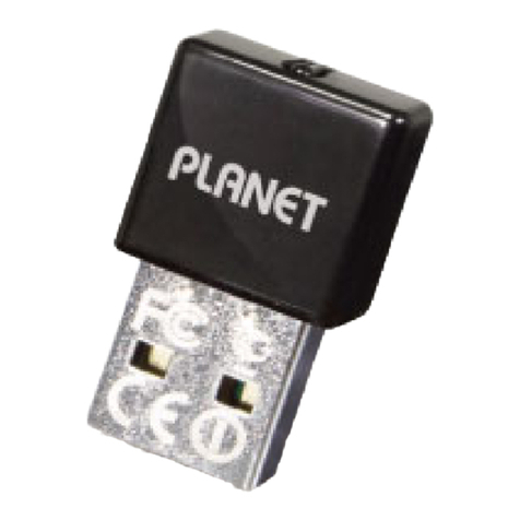
Planet WL-U351 User manual

Wireless USB Adapter
WL-U351
User s Manual

Copyright
Copyrightã2003 by PLANETTechnology Corp.All rightsreserved.No partof this publication may
be reproduced, transmitted, transcribed, stored in aretrieval system, or translated into any language or
computerlanguage,in any formorby any means, electronic, mechanical,magnetic, optical, chemical,
manual orotherwise, without the prior written permission of PLANET.
PLANETmakes no representations or warranties,either expressed orimplied,with respectto the
contentshereofand specifically disclaims any warranties,merchantability orfitness forany particular
purpose.Any software described in this manual is sold orlicensed "as is".Should the programs
prove defective following theirpurchase, the buyer (and not this company,itsdistributor,or itsdealer)
assumes the entirecost of all necessary servicing, repair,and any incidental or consequential
damages resulting from anydefectin the software. Further,this company reserves the right torevise
this publication and tomake changes from time to time in the contentshereof without obligation to
notify any person ofsuch revision orchanges..
All brand and product names mentioned in this manual aretrademarks and/or registered trademarks of
their respective holders.
Federal Communication Commission Interference Statement
This equipment has been tested and found tocomply with the limitsfor aClass Bdigital device,
pursuant toPart 15 ofFCC Rules. These limitsaredesigned to provide reasonable protection against
harmful interference in aresidential installation.This equipment generates,uses, and can radiate
radio frequency energy and,ifnot installed and used in accordance with the instructions, may cause
harmful interference to radio communications. However,there is no guarantee that interference will
not occur in aparticular installation. Ifthis equipment does cause harmful interference to radio or
television reception,which can be determined by turning the equipmentoffand on,the useris
encouraged to try to correct the interference by one or more of the following measures:
1. Reorientor relocate the receiving antenna.
2. Increase the separation between the equipmentand receiver.
3. Connect the equipmentinto an outlet on acircuitdifferent from thatto which the receiver is
connected.
4. Consult the dealer or an experienced radio technician forhelp.
FCC Caution:
Toassure continued compliance.(example-use only shielded interface cables when connecting to
computeror peripheral devices). Any changes or modifications not expressly approved by the party
responsible for compliance could void the user s authority to operate the equipment.
This device complies with Part 15 of the FCC Rules. Operation is subject to the Following two
conditions:(1) This device may not cause harmful interference, and (2 )this Device must accept any
interference received, including interference thatmay cause undesired operation.
Federal Communication Commission (FCC) Radiation Exposure
Statement
This equipment complies with FCC radiation exposure set forth for an uncontrolled environment. In
order to avoid the possibility ofexceeding the FCC radio frequency exposure limits, human proximity to
the antenna shall not be less than 20 cm(8 inches)during normal operation.
R&TTE Compliance Statement
This equipmentcomplies with all the requirementsof DIRECTIVE 1999/5/CE OF THE EUROPEAN
PARLIAMENTAND THE COUNCILOF 9March 1999 on radio equipment and telecommunication
terminal Equipment and the mutual recognition of theirconformity (R&TTE)
The R&TTE Directive repeals and replaces in the directive 98/13/EEC (Telecommunications Terminal
Equipmentand Satellite EarthStation Equipment) As of April 8,2000.
Safety
This equipment is designed with the utmost carefor the safety of those who install and use it. However,
special attention must be paid to the dangersof electric shock and static electricity when working with
electrical equipment. All guidelines of this and of the computer manufacture must therefore be allowed
at all times to ensure the safe use of the equipment.
EU Countries Not Intended for Use
The ETSI version ofthis device is intended forhome and office use in Austria Belgium,Denmark,
Finland, France (with 4 Frequency channel restrictions). Germany, Greece, Ireland, Italy, Luxembourg,
The Netherlands, Portugal, Spain (with 2Frequency channel restrictions), Sweden and United
Kingdom.
The ETSIversion of this device is also authorized foruse in EFTAmember states Iceland,
Liechtenstein, Norway and Switzerland.
Revision
User s Manual for PLANET Wireless USB Adapter
Model: WL-U351
Rev: 1.0 (May. 2003)
Part No. EM-WLU351

TABLE OF CONTENTS
CHAPTER 1 INTRODUCTION ..............................................................1
1.1 Features..............................................................................................1
1.2 Application...........................................................................................1
1.3 Specification........................................................................................3
1.4 Package Contents...............................................................................4
1.5 Minimum System Requirements..........................................................4
1.6 SAFETYPRECAUTION......................................................................4
CHAPTER 2 INSTALLATION PROCEDURE ............................................5
2.1 Hardware and Driver Installation.........................................................5
2.2 UtilityInstallation..................................................................................7
CHAPTER 3 CONFIGURATION UTILITY ...............................................10
3.1 Wireless Connection..........................................................................10
3.2 More Setting…...................................................................................11
3.3 WEPEncryption................................................................................12
3.4 Advanced Setting...............................................................................13
3.5 Information........................................................................................14
CHAPTER 4 TROUBLESHOOTING ......................................................15

1
Chapter 1 Introduction
WithIEEE 802.11b standard-based, WL-U351 provides 11Mbps wireless networking for USB-enabled
desktops or notebooks.It can operatein either Ad-Hoc mode (Pointto Point/Pointto Multipoint without
Access Point)or Infrastructure mode (Point to Point/Point to Multipoint with Access Point).
WL-U351 provides with an internal patch antenna,and thus making itssize more compact. Regarding
the platformcompatibility, WL-U351 supportsmost popularoperating systems including Windows98,
Me, 2000 and XP. Plus 64-bit and 128-bitWEP(Wired EquivalentPrivacy) Encryption feature, WL-U351
offers areliable and private wireless network connection. Itsdatarate support 11, 5.5, 2and 1Mbps.
Withitsauto-fallback function,the data ratecan be move tolower speed if signal quality is not good
enough.
The WL-U351 provides full mobility and seamless roaming featurefor mobile usersto keep network
connection across access points. Its range of coverage is up to 300 feet indoor and 800 feet outdoor.
1.1 Features
l 2.4GHz ISMband, unlicensed operation
l Wireless connection without the hassles and cost ofcabling
l Wireless LAN IEEE 802.11b compliant
l Up to 11Mbps data rate with CSMA/CA
l Utilize Direct Sequence Spread Spectrum (DSSS) Technology to provide robust,
interference-resistant solution in a multi-user environment
l Support 64/128-bit WEPkey
l Working range up to 300 feet indoor and 800 feet outdoor
l SupportAd-Hoc / Infrastructure mode
l Roaming capability to provide mobile computing for mobile worker to access network
resources anywhere in the field
l Seamless integration with IEEE 802.3 LAN through IEEE 802.11b compliant Access Point
l Supportsmostpopularoperating systems including Windows 98/Me/2000/XP
1.2 Application
Infrastructure
The WL-U351 provides access to awired LAN for wireless workstations. Anintegrated wireless
and wired LAN is called an Infrastructure configuration. Agroup of WL-U351 PC users and an
Access Pointcompose aBasic Service Set(BSS). Each WL-U351 PC in aBSScan talk to any
computerin the wired LAN infrastructure via the Access Point.
An Infrastructureconfiguration extends the accessibility of aWL-U351 equipped PC to awired
LAN, and doubles the effective wireless transmission range for 2WL-U351 PCs. Since the Access
Point is able to forward datawithin itsBSS, the effective transmission range in an infrastructure
LAN is doubled.
The use of aunique IDin aBSS is essential. All WL-U351 equipped PCsconfigured without
roaming options in an independent BSS must be configured with aBSS ID corresponding tothe
WL-U351 used in the BSS. Check your WL-U351 for itsBSS ID or use the SiteSurvey function on
Configuration Utility program to determine the BSS ID.

2
The InfrastructureWireless LANconfiguration is appropriate for enterprise-scale wireless access
to a central database, or as awireless application for mobile users.
Infrastructure mode also supportsroaming capabilities for mobile users. More than one BSS can
be configured as an Extended Service Set (ESS).The continuous network allowsusers toroam
freely within an ESS. All WL-U351 PCs or other IEEE 802.11b compliant wireless adapter within
one ESS must be configured with the same ESS ID and use the same radio channel.
Before enabling an ESS with roaming capability,choosing afeasible radio channel and optimum
Access Point position is recommended. ProperAccess Point positioning combined with aclear
radio signal will greatly enhance performance.
Ad-Hoc
An Ad-Hoc wireless LAN is agroup of computers, each equipped with one WL-U351 adapter or
other wireless adapters, connected as an independent wireless LAN.Computersin aspecific
Ad-Hoc wireless LAN must be configured to share the same radio channel.
Ad-Hoc wireless LAN configurations areappropriate for branch level departmentsorSOHO
operations.
WL-U351 offers a fast, reliable, cost-effective solution for wireless client access to the network in
applications like these:
1. Remote access to corporate network information
E-mail, file transfer and terminal emulation.
2. Difficult-to-wire environments
Historical or old buildings,asbestos installations, and open area where wiring is difficultto
employ.

3
3. Frequentlychanging environments
Retailers, manufacturers and banks that frequently rearrange the workplace and change
location.
4. TemporaryLANs for special projects or peak time
Trade shows, exhibitions and construction sites need temporary setup for a short time period.
Retailers, airline and shipping companies need additional workstations for a peak period.
Auditors require workgroups atcustomer sites.
5. Access to database for mobile workers
Doctors, nurses, retailers,white-collar workers need access to database while being mobile in
the hospital, retail store or office campus.
6. SOHO (Small Office and Home Office)users
SOHO users need easy and quick installation of a small computer network.
7. High securityconnection
The wireless security network installs quickly and provides the flexibility to reconfigure easily.
1.3 Specification
Product 11Mbps Wireless USB Adapter
Models WL-U351
Attach Interface USB V1.1 full 12Mbps. Mini-type USB connector
LED Indicator Power
Operating Frequency /
Channel
2.412~2.462GHz (FCC, Canada) / 11 Channels
2.412~2.4835GHz (Japan, TELEC) / 14 Channels
2.412~2.472GHz (Euro ETSI) / 13 Channels
2.457~2.462GHz (Spain) /2 Channels
2.457~2.472GHz (France) / 4 Channels
RF Modulation Direct Sequence Spread Spectrum (DSSS) Technology
(CCK, DQPSK, DBPSK)
RF Output Power 16dBm (Typical)
Data Rate 11, 5.5, 2,1 Mbps with auto-rate fall back
Media Access Protocol CSMA/CA + ACK, IEEE802.11b Compliant
Antenna Internal patch antenna
Range Up to 800 feet outdoor and 300 feet indoor
Working Mode Ad-Hoc, Infrastructure
Management Utility or Windows XP built-in management interface
STANDARDS COMPLIANCE
Electromagnetic
Compatibility
FCC, CE

4
1.4 Package Contents
Before installation, please check the items of your package. The package should include the
following items:
· One Wireless USB Adapter
· One USB Cable
· One CD-Based software (Including the Configuration Utility, Driver and User s Manual)
· One Quick Installation Guide
If any ofthe above items are missing, contact your supplier as soon as possible.
1.5 MinimumSystem Requirements
Before installation, please check the following requirementswith your equipment.
· Pentium Based (above) IBM-compatible PC system with an USB support
· CD-ROMdrive
· One Available USB Connector
· Windows 98SE/2000/ME/XP Operating System
· At least 8 Mbytes of free disk space for utility and driver installation
1.6 SAFETY PRECAUTION
Only use the accessories and connection cables attached withthe device package. Otherwise, the
device may not function. If you miss ordamage the accessories or connection cables, please
contact yourlocal dealer.

5
Chapter 2 Installation Procedure
Before you proceed with the installation, it is necessary that you have enough information about the
Wireless USB Adapter.
2.1 Hardware and Driver Installation
The following installation operates under WindowXP.Procedures will be the same for Windows
98SE/ME/2000.
Note: If you ever install any Wireless USB Adapter before, please uninstall t
he old driver and
utility first.
A. InsertWL-U351 to your computer, system will automatically detectthe adapter and
showthe following window.Select “Install from a list orspecific location [Advanced]”
and click “Next>”.
B. InsertDrivers and User smanual CD to your CD drive (suppose D:\).Select “Include
the location in the search”and click”Browse”button to specify
“D:\Drivers\WL-U351\WinXP”directory and then click “Next>”.

6
C. The Hardware Installation boxwill appear, click “Continue Anyway”to start driver
installation.
D. Click “Finish”to complete the driver installation.

7
2.2 UtilityInstallation
The provided utility can be installed in windows 98SE/ME/2000/XP system. Due to the Windows XP
has built-in wireless network utility, you may decide to use the system s utility or the one provided by
WL-U351.It is strongly recommended to using the provided WL-U351 utility.The following
installation operates under WindowXP.Procedures will be the same for Windows 98SE/ME/2000.
Note: If you want to use this utility in windows XP system,the system built-in utility must be
disabled first. Please click the “Start”button and choose “Connect To ”.Select the
“Properties”from “Wireless Network Connection”,click on the “Wireless Networks”
tab.
Clear the checkboxin front of “Use Windows to configure my wireless network
settings”.Then click “OK”button to finish the setting.

8
A. InsertDrivers and user s manual CD to your CD drive (Suppose D:\).
B. Run “setup.exe”under “D:\Utility\WL-U351\”directory, or click “Start”button and choose
“Run”.In the box appears, enter “D:\Utility\WL-U351\setup.exe”(where “D”is the letter
of your CD-ROMdrive). Execute the “Setup.exe”program under the “Utility”
folder.The following InstallShield Wizard boxwill showup to guide you howto install
properly then click “Next”.
C. The “Choose Destination Location”screen will showyou the default destination chosen
by the program. If you want to install the utility in another location, click the “Browser”
button and select an alternatedestination.Click “Next”button to continue.
D. The program will finish the installation automatically.

9
E. After completing the Utility installation,you can click “Start”button and select “PLANET
WL-U351”from “Programs”. Click “Configuration Utility”option.
F. The Configuration Utility icon will be shown on system tray, if not, that mean the
installation is fail.Please uninstall the driver from the system then repeat the installation
process.
Now,WL-U351 is successfully installed and ready to use.

10
Chapter 3 Configuration Utility
The Configuration Utility is a powerful application that helpsyou to configure WL-U351 and monitor
the statistics of the communication process. By Double Click the icon on the system tray will brings
you to the configuration mode. This utility can be used to change the following configuration
parameters when the device is active.
Note: Click the “Exit”button will exit the configuration application.
3.1 WirelessConnection
The beginning screen displays all the information of wireless stations nearby and check the link
status while WL-U351 is associating to one of the wireless station.
u Network Adapter: Displays the product information.
u Available Network: Displays all the SSID and Signal Strength of wireless stations nearby.
Tosearch the available wireless stations, please click “Refresh”button. You can associate
WL-U351 to the wireless station on the listby double-clicking the station directly.
u Current Network Information: Displays the information about the wireless network
which WL-U351 is connecting to. The information includes Channel, Type, SSID, TX Rate
and WEPsettings.Please refer to section 3.2 for detailed descriptions.
u More Settings: Press this button for more settings including disable/enable WEP and
Power Saving Mode. Please refer to Section 3.2,3.3 and 3.4 for detailed descriptions.
u Link Status: Displays the status ofthe wireless connection.

11
u Signal Strength:Indicates the signal strength level.
u Link Quality: Indicates the quality of active link.
u TX/RX Frame: Shows the number of valid transmitted/received dataframes.
3.2 More Setting…
You can access this screen byclicking on “More Setting…” button. It allows you to designate the
wireless network which WL-U351 intends to connect to, enable/disable the WEP data encryption,
save or load the setting values into/from a file, etc.
u General Connection Settings: Displays information including Channel, SSID, Tx Rate and
Network Type. You can click “Change”button for modifying these values.
Ø Channel: Shows the number of the radio channel used for the networking. Only
Access Points and Ad-Hoc nodes create the BSSID. This parameter is notactive in
the Infrastructure operation mode.
Ø SSID: Shows the SSID of the BSS that one willing to join.
Ø Any: If “Any“check boxis enabled,WL-U351 will survey and connectto one of the
available wireless stations without checking the consistency of channel and SSID
with the wireless station
Ø Tx Rate: Shows the DataTransfer Rate. There are 1 Mbps, 2Mbps, 5.5 Mbps, 11
Mbps, and auto mode. IfAutoMode is been selected, the device will select the most
suitable rate automatically.

12
Ø Network Type:
Infrastructure: This mode requires the presence of an APorRouter to create a
wireless network. All the communication is processed through the AP or Router.
Ad Hoc: This mode enables wireless network adapters interconnecting without
through AP or Router. Select this mode if there is no APor Router in the network
u Encryption Setting: You can setup the WEP keyfor thedataencryption within the
network. Please refer to Section 3.3 for detailed descriptions.
u Profile Name: Input the profile name to write the setting values ofWL-U351 to the file or
load the setting values from the file you designate.
u Load profile setting: Load the setting values from the file entered in the “Profile Name“.
The newsettings will be activated immediately.
u Write Current Setting to profile:Writethe current setting values to the file entered in the
“Profile Name“. Please record the file name the data is saved.
u Load factorydefault setting: To restore to factory default, please press this button. The
default values are as follows.
Channel: 6
TxRate: Auto
SSID: Any
Network Type: Infrastructure
3.3 WEP Encryption
WEPis an authentication algorithm,which protectsauthorized Wireless LAN users against
eavesdropping. The Authentication type and WEPkey must be the same as the wireless stations
within the network. WL-U351 supports 64/128-bitWEP Encryption function. With this function,
your data will be transmitted over the Wireless network securely.

13
u Authentication Mode: This parameter mustbe consistence with the associated wireless
station.
Open System –No authentication is needed among the wireless stations.
Shared Key –Only wireless stations using a shared key (WEPKey identified) are
allowed to connecting each other. Setup the same key as the wireless stations which
WL-U351 intends to connect.
Auto –Auto switch the authentication algorithm depending on the wireless stations
which WL-U351 is connecting to
u KeyLength: Select the 64-bit or 128-bit to encrypt transmitted data. Larger key length
will provide higher level of security, but the throughput will be lower.
u Default KeyID: Select one of the keys (1~4) as the encryption key.
u KeyValue:The keys are used to encrypt datatransmitted in the wireless network. Fill the
text boxby following the rules below:
64-bit –Input 10 digit Hexvalues (in the “A-F”, “a-f”and “0-9”range)as the encryption
keys. For example: “0123456aef“.
128-bit –Input 26 digit Hexvalues (in the “A-F”, “a-f”and “0-9”range) as the encryption
keys. For example: “01234567890123456789abcdef“
3.4 Advanced Setting
This screen allows user to enable/disable power saving mode, setup the fragmentation threshold
and RTS/CTS threshold of WL-U351.
u Power Saving Mode: Check the check boxto enable power saving mode. You
may control the power consumption of WL-U351 by adjusting the save power
level from 1 to 4. The higher power save level selected, the lower power used.
But lower power is supplied may slowdown the transmission rate of WL-U351.

14
u Fragmentation Threshold:The value defines the maximum size ofpackets, any packet
size larger than the value will be fragmented.If you have decreased this value and
experience high packet errorrates,you can increase it again, but it will likely decrease
overall network performance. Select a setting within a range of 256 to 2305 bytes.Minor
change is recommended.
u RTS/CTS Threshold: Minimum packet size required for an RTS/CTS (Request to
Send/Clear to Send). For packetssmallerthan this threshold,RTS/CTS is not sent and
the packet is transmitted directly to the WLAN. Select asetting within arange of 0to2305
bytes. Minor change is recommended.
3.5 Information
This screen shows the current Driver, Firmware, Utility Version, MAC Addressand
Contact Information ofthis device.

15
Chapter 4 Troubleshooting
This section provides solutions to problems usually encountered during the installation and operation
of this Wireless USB Adaptor. Read the description belowto solve your problems.
What is the IEEE 802.11b standard?
The IEEE 802.11b Wireless LAN standards subcommittee, which is formulating astandardfor
the industry.The objective is toenable wireless LAN hardware from different manufactures to
communicate.
What IEEE 802.11 feature are supported?
The product supportsthe following IEEE 802.11functions:
CSMA/CAplus Acknowledge protocol
Multi-Channel Roaming
Automatic Rate Selection
RTS/CTS feature
Fragmentation
Power Management
What is Ad-hoc?
An Ad-hoc integrated wireless LAN is agroup of computers, each with aWLAN adapter,
connected as an independent wireless LAN.Ad hoc wireless LAN is applicable ata
departmental scale for a branch or SOHO operation.
What is Infrastructure?
An integrated wireless and wireless and wired LAN is called an Infrastructureconfiguration.
Infrastructure is applicable toenterprise scale for wireless access tocentral database,or
wireless application for mobile workers.
What is BSS ID?
Aspecific Ad hoc LAN is called aBasic Service Set(BSS). Computersin aBSS mustbe
configured with the same BSSID.
What is WEP?
WEPis Wired Equivalent Privacy,adataprivacy mechanism based on a40 or104 bit shared
key algorithm, as described in the IEEE 802 .11 standard.
Can Wireless products support printer sharing?
Wireless productsperform the same function as LAN products. Therefore, Wireless products
can work with Netware, WindowsNT/2000/XP,or otherLAN operating systems to support
printeror file sharing.
Would the information be intercepted while transmitting on air?
WLAN features two-fold protection in security.On the hardware side, as with Direct Sequence
Spread Spectrum technology,ithas the inherentsecurityfeature ofscrambling.On the
software side, WLAN series offer the encryption function (WEP) toenhance security and
Access Control. Users can setit up depending upon their needs.
What is DSSS? What is FHSS? And what are their differences?
Frequency-hopping spread-spectrum (FHSS) uses anarrowband carrier thatchanges
frequency in apattern thatis knownto both transmitterand receiver.Properly synchronized,
the net effect is to maintain a single logical channel.To an unintended receiver, FHSS appears
to be short-duration impulse noise. Direct-sequence spread-spectrum (DSSS) generates a
redundant bit pattern for each bit to be transmitted.This bit pattern is called a chip (or chipping
code).The longer the chip, the greater the probability that the original datacan be recovered.
Even if one ormore bitsin the chip are damaged during transmission, statistical techniques
embedded in the radio can recover the original data without-the need for retransmission. To an
unintended receiver,DSSSappears as lowpower wideband noise and is rejected (ignored)by
mostnarrowband receivers.
What is Spread Spectrum?
Spread Spectrum technologyis awideband radio frequency technique developed by the
military for use in reliable, secure,mission-critical communication systems. Itis designed to
trade offbandwidth efficiency for reliability,integrity,and security.In other words, more
bandwidth is consumed than in the case of narrowband transmission,but the trade off

16
produces asignal that is, in effect, louder and thus easier to detect,provided that the receiver
knowsthe parametersof the spread-spectrum signal being broadcast. If areceiver is not tuned
to the rightfrequency,aspread –spectrum signal looks like background noise.There are two
main alternatives, Direct Sequence Spread Spectrum (DSSS) and Frequency Hopping Spread
Spectrum (FHSS).
Table of contents
Other Planet Adapter manuals

Planet
Planet WNL-U553 User manual

Planet
Planet BT-410U User manual

Planet
Planet DMA-100W User manual

Planet
Planet VIP-161W User manual

Planet
Planet WL-U357v2 User manual

Planet
Planet WTV-3000 User manual

Planet
Planet VIP-161W User manual

Planet
Planet ENW-3700 User manual

Planet
Planet ENW-9801 User manual

Planet
Planet ENW-980X Series User manual

Planet
Planet POE-161 User manual

Planet
Planet PL-551 User manual

Planet
Planet WNL-U553 User manual

Planet
Planet VIP-156 User manual

Planet
Planet WTV-3000 User manual

Planet
Planet WL-3565 User manual

Planet
Planet ENW-9801 User manual

Planet
Planet POE-151 User manual

Planet
Planet VIP-156 User manual

Planet
Planet WDL-U601AC User manual