Plasson Rion Sun Lounge User manual

Sun Lounge Assembly Instructions
Modular greenhouses, garden sheds, outdoor garden elements and accessories
Designed and manufactured by Rion
A Member of the Plasson Group
Rion Ltd.
Cabri 25120 Israel
Tel: +972-4-995-2666, Fax: +972-4-995-2677
email: [email protected]
homepage: http://www.rion.com

© 2010 by Rion
Authorized Rion Distributors
USA
Backyard Living Source, Inc. - BLS
800 South Industry Way, Suite 350
Meridian, ID 83642
+208-287-6601
Fax: 208-287-6602
www.ecogreenhouse.com
Canada
Canada Greenwall Solutions Inc.
10-8707 Dufferin St., Suite # 384
Vaughan, Ontario, Canada L4J 0A6
+905 597 5710
Fax +905 597 5710
www.greenwallsolutions.com
www.canada-greenhouse-kits.com
Australia
Oldfields Pty Ltd
8 Farrow Road
Campbelltown N.S.W. 2560
+61 2 4627 0777
Fax: +61 2 4627 0999
http://www.oldfields.com.au/treco/index.htm
Germany
CLEMENS HOBBYTEC GmbH
Rudolf-Diesel-Str. 8
D-54516 Wittlich / Germany
+49 (0) 6571 / 929-222
Fax: +49 (0) 6571 / 929-198
www.clemens-hobbytec.de
Korea
Dowin Polychem Co., Ltd
1031-2, Banbaehomestel #209
Bangbae-dong, Seocho-gu
Seoul, Korea
+82-2-583-8511
Fax : +82-2-583-8512
www.rionkorea.com
South Africa
Easy Greenhouses CC
8 Sherwell Avenue, Boskruin Ext 5
Johannesburg, South Africa 2154
Sales and Support: Linda Hill
+27 11 792 7583
Mobile: +27 82 777 6681
www.easygreenhouses.co.za
Great Britain
Two Wests & Elliott
+01246 451077
Fax: +01246 260115
www.twowests.co.uk

1
Safety First
• Please read these Assembly Instructions completely before assembly and keep them in your records so you
can refer to them if you wish to add options or make repairs.
• The instructions in this manual lead you through each step in the assembly process. It is important for you to
follow them closely.
• We recommend that you use gloves during assembly.
• Rion is not responsible for the misuse of tools or parts.
• If local building codes require permits or licenses make sure that they are acquired before beginning.
• Your Greenhouse should be securely anchored to the prepared foundation using the recommended
hardware.
• If you prepare a concrete foundation do not excavate and pour concrete in frozen ground.
• Exercise caution when lifting heavy assemblies.
• Do not attempt to assemble your Greenhouse in high winds.
• We recommend that you place your Greenhouse in a spot where it will receive direct sunlight and will be
protected from the wind as much as possible. The door should not face prevailing winds.
• When your Greenhouse is fully assembled examine it for sharp edges and trim with a razor knife if
necessary.
• Close all roof vents in high winds.
• It is important to clear your Greenhouse of snow in the winter.
• If you live in a hot climate, where outside temperatures exceed 46° C (115° F) in the sun or 36° C (99° F) in
the shade, this may cause the temperature inside the greenhouse to exceed 55° C (131° F). Such conditions
may harm your plants and will damage the greenhouse by warping structural profiles. In order to prevent
damage:
• Ensure good ventilation during hot days.
• Make sure that the temperature inside the greenhouse never exceeds 55° C (131° F) by providing a
shading screen, such as the Rion ShadeNet (available as an option).
Note: Rion is not responsible for any damage due to high temperatures.
Important: Make sure that you check the contents of the greenhouse packaging against the
packing list and the required parts for your model on page 4 and following. Do
not begin assembly if any parts are missing.
Required Tools
Before you start assembly have the following available:
•Powerdrill
• Measuring tape
•Level
• Scissors
•Gloves
• Razor knife
• Sponge and soapy water
Note: You may find some parts easier to assemble if you first moisten them with soapy water.
Accessories
Rion offers a wide range of accessories for your greenhouse from modular bases for the foundation, automatic
window openers, and shelving for your plants.

2Sun Lounge Assembly Instructions
Introduction
Congratulations on purchasing an Sun Lounge. We are certain that it will give you many happy years of
pleasure in your garden.
Sun Lounge has been designed to be as easy to put together as it is beautiful to look at. Most of the work can be
done by a single person. Only attaching the roof requires the help of a family member or neighbor for a short
while.
Easy assembly methods eliminate the need for tools or special
expertise.
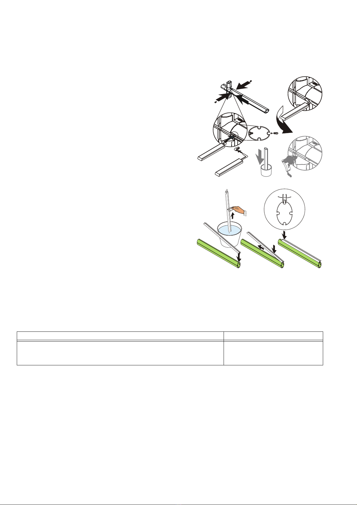
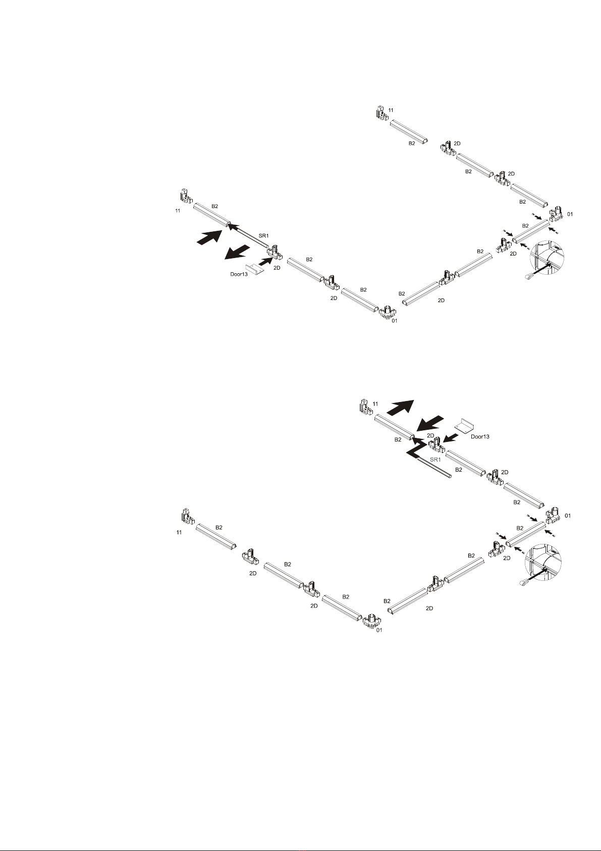
Connect the specified parts.
Match the holes in the profiles and the connectors. Place a
pin on the pin tool and push the pin through the lined-up
holes to lock the parts in place. Many connections require
pins on both sides.
Note: Extra pins are included.
If you wish to disassemble the parts at any time, remove the
pins using the pin tool. Place the end into the exposed hole
and lever the pin out.
If a hole in the connector is missing, drill a hole with a 6 mm
(¼") drill bit through the assembled profile and then insert the
pin.
In extremely rare cases connectors will not slip into some
round or oval profiles. In this case place the affected part into
10 cm (4”) of boiling water for 15 seconds before connecting.
Important: In order to maintain the life of your
greenhouse, it is essential to insert glazing elements fully
and completely.
Moisten the glazing element with soapy water.
Insert one end of the glazing element into the profile until it
snaps into place.
Push the glazing element along its length.
Continue until the end of the glazing element snaps in place.
The callout () shows an enlarged cross-section of the profile and glazing element when it is seated correctly
The panels in your RionSun Lounge are protected by a special plastic film that must be removed before
installation. Depending on the type of panels included in the model you have ordered, follow the instructions
below:
Note: In some models profiles have identification stickers. We recommend removing them as you work.
Sun Lounge assembly is done in the following steps:
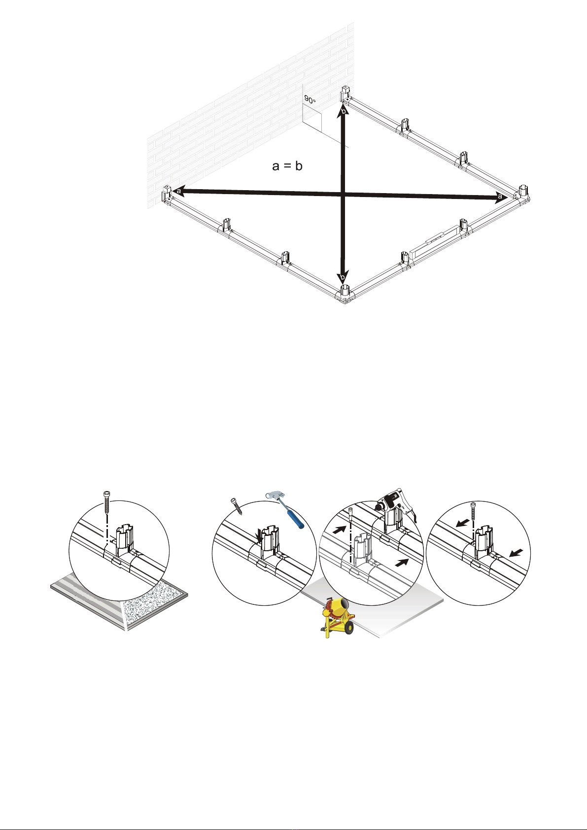
Prepare a Foundation for Your Sun Lounge (page 3)
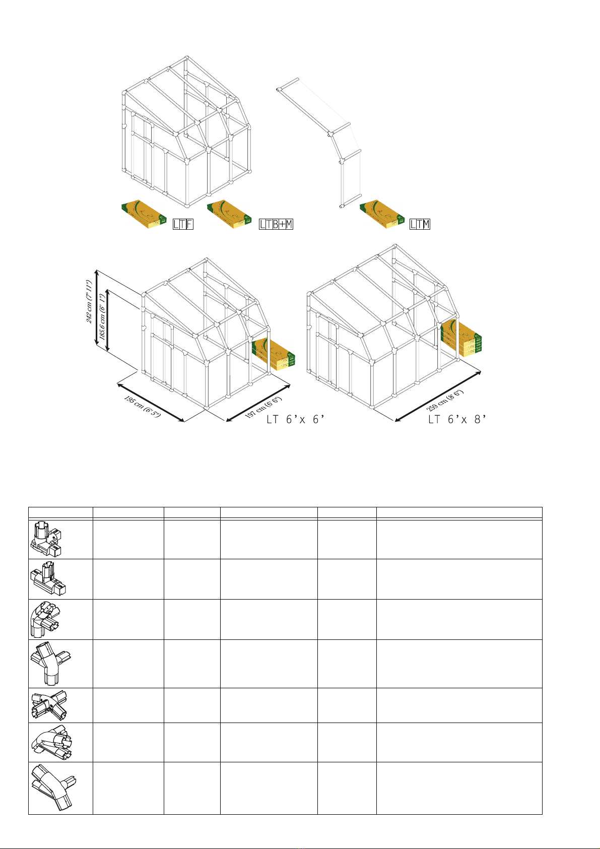
Identify Sun Lounge Parts (page 4)
Prepare Your Parts for Assembly (page 6)
Lay Out The Sun Lounge Frame (page 7)
Secure the Frame to Foundation (page 8)
Assemble the Sun Lounge Pediments (page 9)
Assemble the Roof Framework (page 11)
Prepare the Roof for Panels (page 12)
Raise the Sun Lounge Roof (page 13)
Secure Sun Lounge to the Wall (page 15)
Cover the Roof (page 16)
Seal Panels (page 19)
Assemble the Door (Left Entrance Option) (page 20)
Attach the Door (Left Entrance Option) (page 21)
Assemble the Door (Right Entrance Option) (page 22)
Attach the Door (Right Entrance Option) (page 23)
Final Touches (page 24)
Polycarbonate Panels Acrylic Panels
Polycarbonate panels have plastic film indicating the outside for UV
protection. Remove the plastic film as the panels are installed to be sure
that the UV protection faces the correct side.
Acrylic panels are protected by
plastic film on both sides. Remove
the plastic before installation.

3
Prepare a Foundation for Your Sun Lounge
The Sun Lounge is secured to the wall by using supplied frame clamps and screws, screw/concrete anchor sets
or expansion anchors (not supplied) depending on the wall surface. They should be 6 mm (B”) in diameter and
no less than 40 mm (1A”) long. Make sure that you have checked with your local authorities regarding any
required building permits. Required quantities are shown below.
Decide at this time the final orientation of your Rion Sun Lounge. We recommend that you place your Sun
Lounge against a wall that receives direct sunlight and is protected from the wind as much as possible.
It is important to clear your Sun Lounge of snow in the winter.
Modular Base
If you have purchased the optional Sun Lounge Modular Base follow the assembly instructions in the
packaging. The Sun Lounge Modular Base can be placed in an excavated hole or on the ground. In either case
you will require approximately 0.21 cubic meters (7.4 cubic feet) per section of gravel or earth or other suitable
material to fill the base. All required hardware and tools are included.
Wood Deck
Your Sun Lounge can be secured to a wood deck with screws (not supplied) through the frame connectors. Use
screws that are 6 mm (B”) in diameter and no less than 70 mm (2C”) long. Make sure that the wood deck
itself is securely anchored to the ground.
Concrete Foundation
Prepare a poured concrete foundation according to local building codes. Do not excavate and pour concrete in
frozen ground.
Pour your foundation according to the size of the Sun Lounge model you have selected. Make sure that the
foundation is at least 10 cm (4”) larger than the size of the Sun Lounge.
The Rion Sun Lounge is secured to the concrete foundation using screws and concrete anchors or expansion
anchors (not supplied). They should be 6 mm (B”) in diameter and no less than 70 mm (2C”) long. A drill with
a suitable masonry bit is required. See quantities below.
LT 6’ X 6’ LT 6’ X 8’ Description
12 14 40 mm x 6 mm (1A” x B”) screw, screw/anchor set or expansion anchor
LT 6’ X 6’ LT 6’ X 8’ Description
14 16 70 mm x 6 mm (2C” x B”) Screws
Model Sections Foundation Width Foundation Length
LT 6’ X 6’ LTF, LTB+M 2.05 meter (6’ 8M”) 2.07 meter (6’ 9A”)
LT 6’ X 8’ LTF, LTM, LTB+M 2.05 meter (6’ 8M”) 2.69 meter (8’ 9G”)
LT 6’ X 6’ LT 6’ X 8’ Description
14 16 70 mm x 6 mm (2C” x B”) Screw/anchor set or expansion anchor

4Sun Lounge Assembly Instructions
Identify Sun Lounge Parts
Because of the Sun Lounge modularity, you may purchase up to two LTMs to fit your needs.
Take a minute to make sure you have everything you need.
Note: Do not proceed with assembly if any parts are missing.
The part code is stamped on each connector. Profiles are listed in order by size, largest to smallest. Panels are
identified with stickers. Exact dimensions can be found in the packing list.
Part Code LTF (Front) LTB+M (Back + Middle) LTM (Middle) Description
01 1 1 0 Corner Frame Connector
2D 4 5 1 T-Frame Connector
3A 0 1 0 Left Rib Connector
4A 1 0 0 Right Rib Connector
5A 2 2 2 Rib Connector
6A 0 1 0 Left Pediment Connector
7A 1 0 0 Right Pediment Connector

5
09 4 2 0 T-Oval Connector
10 0 1 0 Oval Junction Connector
11 1 1 0 Corner Frame Connector
12 1 0 0 Top Right Frame Connector
13 0 1 0 Top Left Frame Connector
14 1 1 1 Top Wall Connector
15 1 0 0 Wall Connector
18 2 0 0 Corner Oval Connector
B1 1 1 0 Base Profile (109 cm, 3’ 6G”))
B2 5 7 2 Base Profile (50 cm, 1’ 7M”)
B12 1 1 0 Base Profile (56.6 cm, 1’ 10J”)
B11 1 1 0 Base Profile (335 cm, 10’11G”)
R1 1 1 0 Round Profile (113 cm, 3' 8A")
R10 1 1 0 Round Profile (79.6 cm, 2' 7J")
R11 1 1 0 Round Profile (129.6 cm, 4’3”)
E1 5 3 1 Oval Profile (113 cm, 3’ 8A”)
E16 1 1 1 Oval Profile (135 cm, 4’ 5L”)
E2 7 8 2 Oval Profile (54 cm, 1’ 9B”)
E15 1 1 1 Oval Profile (80.1 cm, 2’ 7L”)
E13 4 2 0 Oval Profile (60.6 cm, 1’ 11G”)
SR1 1 0 0 Inner Round Profile
DoorW1 1 0 0 Door Handle Connector
DOW1 1 0 0 Lock Holder
PN1 4 5 1 Wall Panel (59.7 x 118.2 cm,
1’ 11A” x 3’ 10L”)
PN54 0 1 1 Lower Roof Panel (60.5 x 92.8 cm,
1’ 11F” x 3’ A”)
PN55 1 1 0 Lower Roof Panel (side) (61.7 x 92.8 cm,
2’ A” x 3’ L”)
PN53 1 1 0 Upper Door Panel (1)
Back Pediment Window (1)
(59.7 x 66.3 cm, 1’ 11K” x 2’ 2D”)
PN51R 1 0 0 Right Pediment Panel
PN51L 0 1 0 Left Pediment Panel
PN57 1 1 0 Upper Roof Panel
(61.7 x 150.8 cm, 2’ J” x 4’ 11E”)
Part Code LTF (Front) LTB+M (Back + Middle) LTM (Middle) Description

6Sun Lounge Assembly Instructions
Prepare Your Parts for Assembly
Remove everything from your packages and sort them
according to part type. Since assembly is done from
taking parts from every box, it is best to put everything
together. The boxes are printed with a ruler to help you
distinguish between profiles.
Note: Protect unassembled panels from the sun to
prevent identification stickers from adhering to the
glazing.
PN56 0 1 1 Upper Roof Panel (side)
(150.8 x 60.5 cm, 4’ 11E” x 1’ 11F”)
PN52R 1 0 0 Pediment Panel (Right)
PN52L 0 1 0 Pediment Panel (Left)
WIN41 0 1 0 Roof Vent
WINH31 0 1 0 Roof Vent Handle
GF 28 31 3 Flexible Glazing Seal (m)
DSN 1 0 0 Door Sealer (packages)
RB8 2 2 1 Roof Glazing (129 cm, 4’ 2N”)
RB7 2 2 1 Roof Glazing (79 cm, 2’ 7D”)
RC8 2 2 1 Top Roof Glazing (92.5 cm, 3’ G”)
RC9 2 2 1 Top Roof Glazing (151 cm, 4’ 11G”)
RD1 2 4 2 Window Roof Glazing
(56.9 cm, 1' 10E")
RD2 1 2 1 Window Roof Glazing
(49.8 cm, 1' 7F")
AW5 1 0 0 Hex Wrench
BC1 10 2 2 Frame Clamp
PIN1 100 130 30 Connector Pin
GT1 1 1 0 Pin and Glazing Tool
AS80 1 0 0 Door Runner Screw/Wingnut
SF 1 1 1 Soft Foam Roof Insulation (roll)
Door12 1 0 0 Sliding Door Top
LI1080 2 0 0 Door Stop (108 cm, 3’6A”)
Door11 1 0 0 Door Sliding Track (121 cm, 3’11F”)
Door13 1 0 0 Door Lead (12 cm, 4C”)
Part Code LTF (Front) LTB+M (Back + Middle) LTM (Middle) Description

7
Lay Out The Sun Lounge Frame
Place the parts of the frame on the prepared foundation. The door can be placed on the left or right face of
your Sun Lounge.
For Sun Lounge with Left Entrance
Slide the SR1 profile
into the B2 frame
profile that will be
used for the doorway.
Place a 2D connector
on the right side of
prepared B2 frame
profile. Place the 2D
connector the
Door13 door lead.
Note: Arrange all 2D
connectors with the
stamped word OUT
facing the outside of the
greenhouse.
Place the other parts
of the frame in place
and lock it together with pins.
For Sun Lounge with Right Entrance
Slide the SR1 profile
into the B2 frame
profile that will be
used for the doorway.
Place a 2D connector
on the left side of
prepared B2 frame
profile. Place the 2D
connector the
Door13 door lead.
Note: Arrange all 2D
connectors with the
stamped word OUT
facing the outside of the
greenhouse.
Place the other parts
of the frame in place
and lock it together
with pins.

8Sun Lounge Assembly Instructions
Push the frame flush
against the wall and
check that it is
perfectly rectilinear by
measuring the
diagonals and
verifying that they are
the same.
Make sure that the
frame is level by using
a level.
Note: The wall to
which you are securing
your Sun Lounge must
be 90° to the foundation.
Secure the Frame to Foundation
Acquire the proper hardware before beginning the next procedure. (See page 5.)
Wood Deck or Rion Modular Base Concrete Foundation
Insert screws into the frame connector
holes and secure them to the wood
deck or modular base until they are
firm but not tight.
Tighten each screw.
Note: All necessary hardware is
included in the Rion Modular Base
packaging.
Mark the foundation through each connector using a scribe or screw.
Carefully move the frame. With a masonry bit suitable for your
concrete anchors or expansion anchors (not supplied) drill holes and
insert.
Move the frame back into place. Make sure that it is still perfectly
rectilinear and the Door13 door slide is in place and lined up.
Secure the screws/anchors until they are firm but not tight.
Tighten each screw.

9
Assemble the Sun Lounge Pediments
For Sun Lounge with Left Entrance
Put the connectors and profiles of the top triangular window of the doorway pediment together except for
the 7A pediment connector.
Remove the plastic film from the PN52R pediment panel and put it in place.
Note: If your model includes polycarbonate panels with UV protection, there is a single plastic film indicating
the outside. Acrylic panels are protected by plastic film on both sides. Remove the plastic before installation.
Slide the 7A pediment connector in place. Take advantage of the flexibility of the profiles.
Attach the Door11 sliding track with AS80 screws and wing nuts through the connectors where shown.
Lock the parts in place using pins.
Attach the E13 profile and the 09 connector to the doorway pediment.
Attach a R10 and two E2 profiles to a 4A pediment rib connector and put them loosely in place.
Remove the plastic film from the PN51R side panel. Make sure that the proper side faces out, and put the
panel in place. Lock all connectors and profiles in place with pins and set the doorway pediment aside.
Put the connectors and profiles of the top triangular window of the rear pediment together except for the 6A
pediment connector.
Remove the plastic film from the PN52L pediment panel and put it in place.
Slide the 6A pediment connector in place. Take advantage of the flexibility of the profiles. Lock the parts in
place with pins.
Put the R10 and three E2 profiles and 3A connector loosely in place.
Remove the plastic film from the PN51L panel. Put the panel in place and lock the parts together with pins.
Place a B12 and E2 profile in place and connect them loosely with a 2D connector.
Remove the plastic film from the PN53 panel, put it where shown, and lock the parts in place using pins.

10 Sun Lounge Assembly Instructions
For Sun Lounge with Right Entrance
Put the connectors and profiles of the top triangular window of the doorway pediment together except for
the 6A pediment connector.
Remove the plastic film from the PN52L pediment panel and put it in place.
Note: If your model includes polycarbonate panels with UV protection, there is a single plastic film indicating
the outside. Acrylic panels are protected by plastic film on both sides. Remove the plastic before installation.
Slide the 6A pediment connector in place. Take advantage of the flexibility of the profiles.
Attach the Door11 sliding track with AS80 screws and wing nuts through the connectors where shown.
Lock the parts in place using pins.
Attach the E13 profile and the 09 connector to the doorway pediment.
Attach a R10 and two E2 profiles to a 3A pediment rib connector and put them loosely in place.
Remove the plastic film from the PN51L side panel. Make sure that the proper side faces out, and put the
panel in place. Lock all connectors and profiles in place with pins and set the doorway pediment aside.
Put the connectors and profiles of the top triangular window of the rear pediment together except for the 7A
pediment connector.
Remove the plastic film from the PN52R pediment panel and put it in place.
Slide the 7A pediment connector in place. Take advantage of the flexibility of the profiles. Lock the parts in
place with pins.
Put the R10 and three E2 profiles and 4A connector loosely in place.
Remove the plastic film from the PN51R panel. Put the panel in place and lock the parts together with pins.
Place a B12 and E2 profile in place and connect them loosely with a 2D connector.
Remove the plastic film from the PN53 panel, put it where shown, and lock the parts in place using pins.

11
Assemble the Roof Framework
Note: Assemble the roof in an
area not too far away from the
completed frame.
Assemble one arch.
Lock the parts in place using
pins.
Assemble the rest of the arches
according to the number of
LTMs you have purchased.
Attach a B2 profile and two E2 oval profiles to the left pediment.
Note: The illustration is of a Sun Lounge with the entrance in the left pediment. The assembly steps are
identical.
Lock the parts in place using pins.
Connect one completed arch to the ribs and continue adding profiles and arches according to the number of
LTMs you have purchased.
Attach the right pediment to the roof and lock it into place using pins.

12 Sun Lounge Assembly Instructions
Prepare the Roof for Panels
Note: The illustration is of a Sun Lounge with the entrance in the left pediment. The assembly steps are
identical.
Attach RB8 and RB7 glazing
elements where shown. Place
one end in the top channel and
push them down along the
length of the profile.
Important: In order to
maintain the life of your
greenhouse, it is essential to
insert glazing elements fully and
completely, using soapy water, as
explained on page 2.
Moisten the
channels of the E2
and B2 profiles with
soapy water. Place
RD1 and RD2
elements on the
profiles by placing
one end in the
channel and
pushing it down
along the length of
the profile.
Note: The openings
of the RD1 profiles
point towards the
openings of the RD2
profiles.

13
Raise the Sun Lounge Roof
Put the R1 round profiles in place.
Add the E1 oval profiles.
Put the B1 profiles on the frame
Place a 15 base connector and a B12 frame profile on the doorway side to complete the framework.
Insert two pins in each column to lock them in place. Do not insert pins in the inner (panel) channels of the
column profiles.
Place the roof on the columns.
Note: You will need the help of another person to lift the roof and put it in place.
Make sure that the roof is in the same orientation as the frame. Lift the roof from both edges and walk
through the door towards the back wall.
Place the roof on the columns and circle around the Sun Lounge and insert the first 1 cm (½”) of the roof
connectors into the columns.
Note: Do not insert the connectors all of the way into the columns at this time in order to provide enough
space to install the panels in the next step.
Sun Lounge with Left
Entrance
Sun Lounge with Right
Entrance

14 Sun Lounge Assembly Instructions
Remove the plastic film from a PN1
panel.
Note: If your model includes
polycarbonate panels with UV
protection, there is a single plastic film
indicating the outside. Acrylic panels
are protected by plastic film on both
sides. Remove the plastic before
installation.
Put the panel in place by gently
curving it so that it enters the side
channels of the columns.
Slide the top of the panel into the
channel in the bottom of the roof.
Continue with the other PN1
panels.
Lower the panel towards the frame.
Continue with this procedure until
all of the PN1 panels are finished.
Panel by panel, circle around the
Sun Lounge and lower the roof into
place. Use the GT1 pin & glazing
tool to guide the corners of the P1
panel into the channels and lock
the completed panel in place with
pins.
Continue with this procedure until
all of the panels are in place and
each connector is locked in place
with pins.

15
Secure Sun Lounge to the Wall
Place a BC1 frame clamp
on the inside of the
frame profile and mark
the concrete with a
pencil. Drill a hole with a
masonry bit suitable for
your 6 mm (B”) x 40
mm (1A”) screw/
concrete anchor set or
expansion anchor (not
supplied).
Secure the frame to the
wall using the BC frame
clamp.
Continue attaching
clamps where shown
below.
Make sure that the
center of the Sun Lounge
roof does not sag.
(You may wish to
waterproof the joint between the Sun Lounge and the wall with silicon.)
Note: Where panels do not interfere you may drill through the holes in the connector instead of using clamps.

16 Sun Lounge Assembly Instructions
Cover the Roof
Moisten the RD2
elements with soapy
water.
Remove the plastic film
from the PN57 panel
and slide the panel
between the RD
glazing elements.
Note: If your model
includes polycarbonate
panels with UV
protection, there is a
single plastic film
indicating the outside.
Acrylic panels are
protected by plastic film
on both sides. Remove
the plastic before
installation.
Important: In order
to maintain the life of
your greenhouse, it is
essential to insert
glazing elements fully and completely, using soapy water, as explained on page 2.
Lock the left side of the panel into place with an RC9 glazing element. Place one end in the channel and
push it down along the length of the profile. Make sure that the end of the RC glazing element is in line with
the bottom of the RD element.
Moisten the RD2
elements with soapy
water.
Assemble the two
WINH31 handles to
the WINH41 Roof
Vent using the
included pins and
place the window in
central section.
Note: If you have a
Sun Lounge model with
more than one LTM, you
may install additional
roof vents in the middle
sections.
Lock the right side of
the PN57 panel and
the left side of the
roof vent in place with
an RC9 glazing
element. Place one
end in the channel
and push it down
along the length of the
profile. Make sure that
the end of the RC
glazing element is in line with the bottom of the RD elements.

17
Moisten the RD2
elements with soapy
water.
Remove the plastic film
from the PN57 panel.
Make sure that the
proper side faces out.
Slide the panel
between the RD
glazing elements.
Note: If your model
includes polycarbonate
panels with UV
protection, there is a
single plastic film
indicating the outside.
Acrylic panels are
protected by plastic film
on both sides. Remove
the plastic before
installation.
Important: In order
to maintain the life of
your greenhouse, it is
essential to insert
glazing elements fully
and completely, using
soapy water, as
explained on page 2.
Lock the both sides of
the last panel with
RC9 glazing elements.
Place one end in the
channel and push it
down along the length
of the profile. Make
sure that the end of
the RC glazing
element is in line with
the bottom of the RD
element.
Continue attaching
PN56 panels and RC9
glazing elements
according to the
number of LTMs you
have purchased.

18 Sun Lounge Assembly Instructions
Moisten the RD elements
with soapy water.
Remove the plastic film
from the PN55 panel.
Make sure that the proper
side faces out. Slide the
panel between the RD1
glazing elements.
Note: If your model
includes polycarbonate
panels with UV protection,
there is a single plastic film
indicating the outside.
Acrylic panels are protected
by plastic film on both sides.
Remove the plastic before
installation.
Important: In order to
maintain the life of your
greenhouse, it is essential
to insert glazing elements
fully and completely, using
soapy water, as explained
on page 2.
Lock the left side of the
PN55 panel into place
with an RC8 glazing
element. Place one end in
the channel and push it
down along the length of
the profile. Make sure that
the end of the RC glazing
element is in line with the
bottom of the RD element.
Continue with the middle
PN54 panels and the back
PN55 panel as described
previously.
Lock all panels into place
with RC8 elements.
Table of contents