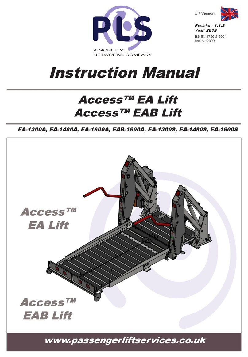
PLS Access ACC-1150 User manual

www.passengerliftservices.co.uk
Instruction Manual
Access™ Van Lift
ACC-1150, ACC-1200, ACC-1280, ACC-1300, ACC-1380
UK Version
Revision: 1.4
Year: 2017
BS:EN 1756-2-2004
and A1:2009
Access™
Van Lift

1
General
1. GENERAL
1.1. Manufacturer
1.2. Markings
1.3. Using the Manual (symbols etc)
1.4. Operator Responsibility
1.5. Health & Safety (Scooters)
2. TECHNICAL
2.1. Main Components Access™ Van
2.2. Dimensions Access™ Van
2.3. Technical Data (Volts, PLS Blue)
3. PRODUCT USE:
3.1. Intended Use
3.2. Improper Use
4. SAFETY DEVICES
4.1. Description of Safety Devices Access™ Van
5. STICKERS
5.1. Description of Labels & Stickers
6. LOGISTICS
6.1. Receipt and Inspection
6.2. Storing the Lift
6.3. Handling
7. INSTALLATION
7.1. Risk Assessment
7.2. General Installation- Box Section Chassis
7.3. General Installation- Open Section Chassis
7.4. Power Pack Mounting Options
7.5. Checking the Power Pack Oil Level
7.6. Hydraulic and Electrical Fittings
7.7. Floor Height Adjustment
7.8. Bridge Plate Adjustment
7.9. Weight Test- Dynamic
7.10. Weight Test- Overload, Drift & Static
7.11. Installation Checklist
7.12. Torque Settings
8. OPERATION
8.1. Standard Operation procedure
8.2. Manual Override
9. CLEANING
9.1. Cleaning Instructions
10. SERVICE AND MAINTENANCE
10.1. UK Service & Warranty
10.2. Loler
10.3. Daily Inspections
10.4. Monthly Inspections
10.5. Six Monthly inspections
10.6. Lubrication
10.7. 31 Point Check
11. DISPOSAL
11.1. Safe Disposal
12. TROUBLE SHOOTING
12.1. Trouble Shooting
13. DIAGRAMS
13.1. Wiring Diagram- Power Pack
13.2. Wiring Diagram- Lift
13.3. Hydraulic Diagram
14. SPARE PARTS
14.1. Contents List of Spare Parts Access™ Van
14.2. Spare parts request form Access™ Van
15. NOTES

1
Passenger Lift Services Ltd
Unit 2 Summit Crescent Trading Estate
Smethwick,
West Midlands
United Kingdom
Tel: +44(0) 0121 552 0660
1.1 Manufacture
1.2 Manufacture
The lift device is manufactured in compliance with the relevant EC directives applicable on the
date of entering the market. Considered a “medical device” pursuant to article 2, point 1),
letter a), rst paragraph of directive 2007/47/EC, the device carries a specic identication plate
which, in addition to the specic technical data also includes the CE marking, guarantee of the
compliance of the device to the directives/ standards referred to the enclosed Declaration of
Conformity.
The plate, a facsimile of which is shown here, is stamped with the data indicating the specic
model and unit.
NOTE: The Lift Serial number will be required for ALL correspondence with factory
Uniformly Distributed
LIFT SERIAL No.
OR
SWL
400 kg
PASSENGER LIFT SERVICES LTD
Tel: 0121 552 0660
Unit 2, Summit Crescent Ind. Est., Off Roebuck Lane,
Smethwick, West Midlands. B66 1BT
Website: www.passengerliftservices.co.uk
CUSTOMER NAME:
INSTALLER NAME:
DATE OF INSTALLATION:
SERIAL NUMBER:
IT IS PROHIBITED TO REMOVE OR TAMPER WITH THE IDENTIFICATION PLATE
General

1
1.3 Using the Manual
This manual aims to provide users and operators with all the information they require to ensure
that they are able both to use the lift appropriately and are able to manage it as autonomously
and safely as possible.
Before performing any operations on the lift, users and operators must carefully read the instruc-
tions given in this publication.
In the event of doubt over the correct interpretation of the instructions, contact the PLS technical
department to obtain the required clarications.
This manual is an integral part of the lift, it must be kept safely by the purchaser and made avail-
able for use by the operators.
The contents of this manual comply with the Directive 2007/47/EC and were drafted following
the guidelines given in UNI 10893:2000. They also comply with the requirements of UNI EN ISO
10535:2007 and BS EN 1789:2007 and A2:2014
Data and drawings are indicative only; with a view to the continuous development and updating
of its products, the manufacturer may modify the contents without notice.
It is prohibited to disclose, edit or use this manual for any other purposes.
This symbol indicates IMPORTANT Information used by the Manufacture and
the User
This symbol indicates areas that need routine maintenance
This symbol indicates Operators areas of responsibility
This symbol indicates that a potentially hazardous situation could occur
This symbol indicates improper use of the lift
This symbol indicates IMPORTANT areas for the Safe operation of the Lift
General

1
1.4 Operators Responsibility
The operator is individually responsible for the safe use and maintenance of the lift.
They are also responsible for the lift users and their own personal safety and in the event
of an accident they will be prosecuted to the full extent of the law if they are deemed
negligent.
Legal action will also be taken if any unauthorised modications are made to the lift
without direct prior written authority by a PLS director.
The lift owner is the person who purchases the product, uses or oversees the
use of the lift, this person is legally responsible for the lift’s safe use.
General
The accompanying person, also known as the operator is responsible for the
safe operation of the lift.
The operator must be full trained in all the operation aspects of the lift such as the transportation
of people with motor deciencies or disabilities. The operator must exhibit the following
characteristics/ attributes for them to safely operate the lift:
PHYSICAL – Possess the required physical qualities/ characteristics sufciently to ensure
safe operation of lift in a safe and controlled manner. Examples include:
• Good hearing & sight
• Physically capable of performing all operational functions of lift
• Not impaired by the consumption of legal and/or illegal substances (such as alcohol
and/ or drugs)
MENTAL - Possess the required mental qualities / characteristics sufciently to ensure safe
operation of lift in a safe and controlled manner. Examples include:
• Understanding & application of the safety rules and procedures while operating the lift.
• Be constantly aware and pro-active to ensure the safety of operator, consumer and
nearby people.
• Have the knowledge/ skills to perform as an assistant and/ or operator in all aspects of
lift operation. E.g. the safe transportation, loading and unloading of disabled and other
passengers.
EMOTIONAL - Possess the required emotional qualities/ characteristics sufciently to
ensure safe operation of lift in a safe and controlled manner. Examples include:
• Work in a calm & safe manner while under stress so to prevent stress from impairing
good judgement.
• To be emotionally stable during normal or abnormal situations
TRAINING – Possess the required training qualities sufciently to ensure safe operation of
lift in a safe and controlled manner. Examples include:
• Completed operational training supervised by an experienced operator in PLS lifts in an
environment which is safe and controlled. Such supervised training should allow
the trainee to gain working experience in all operation aspects of the lift.

The lift owner is responsible for distributing and ensuring that a copy of this
manual is read and fully understood by all potential lift operators before
operating the lift.
No operator will use the lift if they believe it is unsafe and doing so could
injury themselves or others, they MUST report their concerns directly to their
manager or PLS
1
General

1
1.5 Heath & Safety (Scooters)
General

2
2.1 Main Components Access™ Van
Technical
2
Technical
2:1 Main Components
Access™ Van
Power Pack
Carriage
Box Lock
Umbilical
Handrail
Roll Off Ramp
Top Sheet
Extension
Platform
Cassette/ Box
Box
Bridge Plate
Arm
Pump Mounting
Bracket
Manual Pump Handle

2
2.2 Dimensions Access™ Van
Technical
ACC-1150 ACC-1200 ACC-1280ACC-1300ACC-1380
A1150mm 1200mm 1280mm 1300mm 1380mm
B1000mm
1100mm
1000mm
1100mm
1000mm
1100mm
1000mm
1100mm
1000mm
1100mm
C1390mm 1410mm 1410mm 1510mm 1510mm
D825mm
925mm
825mm
925mm
825mm
925mm
825mm
925mm
825mm
925mm
E360mm 425mm 470mm 425mm 470mm
F370mm 400mm 470mm400mm470mm
G95mm 100mm 70mm 100mm 70mm
2
Technical
2.2 D im ens ions
Access™ Van
B=Box Widths
D=Platform
Widths
E=Max Up
F=Max Down
A=Box Length
175mm
200-550mm Bridge Plate
Variations to Suit Vehicle
C=Platform Length
G= Platform Overhang To
Shroud At Max Up
Overall Length =A +40mm (Shroud)

2
2.3 Technical Data Access™ Van
Technical
ACC-1150
ACC-1200
ACC-1280
ACC-1300
ACC-1380
SWL (Kg)
400
400
400
400
400
Voltage (DC) 12V 12V12V12V12V
Pressure (Bar) 130 140 160 140 160
Auxiliary
Hand Pump
Yes YesYesYesYes
Lift Control 2 Button
Handset
2 Button
Handset
2 Button
Handset
2 Button
Handset
2 Button
Handset
2
General
2.3 T echni cal D ata
Access™ Van
Note: Lift weight not including Power-pack & Installation
Kit
The Lift is designed To Transport:
Two walking passengers. The operator should not
attempt to transport more than two people at a time of
increased risk of passenger discomfort. The
passengers also may require extra space for mobility
devices such as sticks and frames
Or:
One person in a wheelchair with or without an
attendant, with a size not larger than the width/
length of platform space available, or weight over
the stated ‘SWL’ capacity

3
3.1 Intended Use
Product Use
The lift is designed for installation on the loading floor of a vehicle designed for transportation
of the disabled in wheelchairs, within the limits of the performances and capacities indicated
in the technical characteristics.
The lift must only be used by an authorised and trained operator, known as the
accompanying person, who possesses the knowledge and physical requirements to safely
perform operations with disabled persons.
Anything that is not specifically referred to in chapter 3.1 is considered IMPROPER USE.
3
PRODUCT USE
3.1 I ntend ed Us e
THE MANUFACTURER DECLINES ALL RESPONSIBILITY
FOR DAMAGE CAUSED TO PERSONS OR PROPERTY OR
TO THE LIFT ITSELF DUE TO ANY USE OTHER THAN
THAT DESCRIBED IN THIS MANUAL.

3
3.2 Improper Use
Product Use
Anything that is not specifically referred to in chapter 3.1 is considered IMPROPER USE.
3
PRODUCT USE
3.2 Improper Use
IT IS FORBIDDEN to climb onto the lift or any of its parts and go up or
down while standing.
It is advisable to always attempt to use the lift on flat/ level ground
No angle of more than 5° from level (in any direction) should be attempted
THE MANUFACTURER DECLINES ALL RESPONSIBILITY
FOR DAMAGE CAUSED TO PERSONS OR PROPERTY OR
TO THE LIFT ITSELF DUE TO ANY USE OTHER THAN
THAT DESCRIBED IN THIS MANUAL.

4
4.1 Description of Safety Devices Access™ Van
Safety Devices
IT IS FORBIDDEN TO DISABLE, REMOVE OR TAMPER WITH THE
EXISTING SAFETY SYSTEMS.
1
Handrail
Standard
2
Handrail Guard
Standard
3
Roll Of Ramp
Standard
4 Bridge Plate
Standard
5
Anti-Slip Surface Cleats
Standard
6 Handrail Extension
Optional
7
Door Safe
Optional
8 Stop Safe
Optional
4
SAFETY DEVICES
4.1 Description of Safety Devices
Access™ Van
1
2
3
4
5
7
8
6
Standard
Standard
Standard
Standard
Standard
Optional
Optional
Optional
Roll Off Ramp
Anti-Slip Surface Cleating

5
5.1 Description of Labels & Sticker
Warning Labels &
Stickers
L
REFLECTIVE
5
WARNING LABELS &
STICKERS
5.1 Description of Labels & Stickers
ACC25130-DB
Access Operation Instructions
Board
ACC 26469
PLS 321
REFLECTIVE
REFLECTIVE
ACC 26469
Uniformly Distributed
LIFT SERIAL No.
OR
SWL
400
kg
PASSENGER LIFT SERVICES LTD
Tel: 0121 552 0660
Unit 2, Summit Crescent Ind. Est., Off Roebuck Lane,
Smethwick, West Midlands. B66 1BT
Website: www.passengerliftservices.co.uk

6
6.1 Receipt and Inspection
Logistics
IF THE DELIVERED DEVICE DOES NOT COMPLY WITH THESE
REQUIREMENTS, NOTIFY THE MANUFACTURER IMMEDIATELY.
STORAGE OF THE LIFT IN CONDITIONS THAT DO NOT
COMPLY WITH THE ABOVE DESCRIPTION SHALL NULLIFY
THE WARRANTY FOR ANY PARTS TO BE REPLACED.
store
Note: If a lift is to be dry stored for more than 12 months then all cylinder seals MUST be
checked before operation
6
LOGISTICS
6.1 Receipt and Inspection
Upon delivery of the lift, you need to perform the following inspections:
- Ensure the product delivered corresponds to the relevant documentation e.g. the order
specification and the transport document.
- Examine packaging to ensure it is undamaged and all parts are intact during
transportation.
- With great care, examine all devices to ensure they haven’t been damaged during
transportation and all parts haven’t been tampered or removed.
- Ensure all documentation required for installation has been supplied.
6.2 Storing The Lift
If the lift is not used, proceed as follows:
-Transport lift to an appropriate storage area, free from atmospheric agents /
elements.
-Ensure all electrical / electronic devices are insulated from external environment so
to prevent humidity damaging those components.
-Storage area selected MUST ensure temperature variation is between 5°C to 50°C
fresh hold.
-Ensure all sliding parts (guides, cylinders ...) are adequately protected from dust,
rust and water damage.
-Do not store for over 6 months. For longer periods of storage, before putting into
service contact the manufacture to have the lift conditions inspected.
6.2 Storing The Lift

HANDLING STAFF MUST WEAR: SAFETY SHOES WITH STEEL
TOE CAP AND NON-SLIP SOLES.
MAKE SURE THAT NO UNAUTHORISED PERSONS ARE
STANDING WITHIN THE RADIUS OF ACTION OF THE
LIFTING/HANDLING MEANS (FORK LIFT TRUCK,
TRANSPALLET, ETC.) DURING THE LIFTING, TRANSPORT AND
HANDLING OPERATIONS.
Procedures for packaging removal are explained below:
•UsingaStanleyKnifewithamaximumbladelengthof10mm,cutalongthe4sidesofthe
baseofthepackaging,removetapeandensurewastecardboardisrecycled
•For wooden crates, remove nails from top panel and those present on the side walls.
STAFF REMOVING THE PACKAGING MUST WEAR:
SAFETY SHOES WITH STEEL TOE CAP AND NON-SLIP SOLES
AND GLOVES.
6.3 Handing
6
LOGISTICS
All lifting and short workshop distance
transportation of packages lifts must be carried
out using a forklift truck.
Safe lifting can only be achieved when using
suitably rated load capacity equipment (Please
refer to Technical Data Table for indicated lift
weight)
6
6.3 Handling
Logistics

7
7.1 General Installation- Risk Assessement
Installation
Assessmentcarriedoutby:Position:Date:
REMEMBER:REVIEWTHEASSESMENTIFTHECIRCUMSTANCESCHANGESIGNIFICANTLY
Location:PassengerLiftServicesLtdRevNo:
Operation/Activity:LiftOperation
Listbelowtheoperations,inyour
opinion,whichinvolveasignificant
hazard,riskofinjury?
Severity
Likelihood
RiskRating
1 2 3 4 5 1 2 3 4 5
=SxL
Stabilityofliftduringoperation
2
1
2
Entrapmentfrommovingparts
2
1
2
Slips,tripsandfalls
3
1
3
Operatingenvironment
3
2
6
Manualoperationoflift
2
1
2
Contactwithhazardoussubstances
2
1
2
Fire
1
1
1
Listpersonsat
risk:
Operators
Noinjuryjustminordamageto
plant,equipmentorstructure
Minorinjury–smallcutorbruise
–firstaidtreatment
Serious–medicaltreatment
required–doctororsmallinjury
clinic
Major–attendanceathospital
accidentandemergency
department
Fatalities
Rare-mayoccuronlyin
exceptionalcircumstances.(0-
20%chance)
Unlikely-conceivable(21-40%
chance)
Moderate-couldoccurat
sometime.(41-60%chance)
Likely-notsurprisedcouldoccur
severaltimes.(61-80%chance)
Certain-tobeexpected,will
occurrepeatedly.(81-100%
chance)
18
Overallrisk
rating
Passengers
Riskratinghasbeendefinedtakingintoaccountthefollowingcontrolmeasures
Controlmeasuresinclude(engineeringqualitycontrol,specialistequipmentinformation/instruction,Customer
responsibilitiesmaintained.
ActionPlan/Controls:-
Allliftsaresuppliedwithsafetyinstructionsandsafeoperatingprocedureswithvisualinstruction
fortheautomaticandmanualoperationoflifts.
Safetyinstructionisalsogeneratedandsuppliedfortheuseofliftsbyscootersandlargepowered
wheelchairs.
Supplyandfittedliftshaveaweighttestcertificateandaninstallationandexaminationreport
completedbyacompetentengineercomplyingto;LiftingOperationsandLiftingEquipment
Regulations1998.
Additionalcontrolsaretobeimplementedandmaintainedbytheenduser,withsixmonthly
inspectionscarriedoutonallliftingequipmentconformingto;LiftingOperationsandLifting
EquipmentRegulations1998.
HastheoverallriskratingbeenreducedtoLow?
Hastheoverallriskratingbeenreducedto
Medium?
HastheoverallriskratingremainedHigh?
Controlsaredeemedadequate-proceedwiththe
operation/activity
X
Consideradditionalcontrols,strictmonitoringof
controlsrequired-proceedwithcaution
Operation/activityisNOTtobeundertakenuntil
additionalcontrolshavebeenimplemented-contact
safetyofficer
Cantheriskbereducedtolowbyintroducingadditionalpreventativeand/orprotectivemeasures?No
SeeRiskAssessmentActionPlanforadditionalprecautions/controlstobeimplemented.
7
INSTALLATION
7.1 G en era l Ins ta lla tion- R isk A ss ess ement
1-7
8-20
21-30

7
7.2 General Installation- Box Section Chassis
Installation
XLWB-F+100W-LH
LIFT DIRECTION
DETAIL A
DETAIL B
BUMPER
THERE ARE USUALLY
TWO OR MORE HOLES
IN THE END OFTHE CHASSIS
WASHER
HOLE
HEX BOLT
NYLOCK
WASHER
HOLE
SPACER
SPACER
HOLE
HEX BOLT
WASHER
SPACER
HEX BOLT
WASHER
HOLE
WASHER
NYLOCK
HOLE
WASHER
NYLOCK
HOLE
BOX LOCK
REAR X
FRONT Y
VEHICLE FLOOR
REAR X FRONT Y
BOX LOCK
BOX SECTION CHASSIS
VIEW ON LHS OF THE BOX
(REAR SECTION OF VEHICLE)
BOX
FRONT MOUNTING BRACKET
G
VIEW ON RHS OF THE BOX
(REAR SECTION OF VEHICLE)
BOX SECTION LARGE CHASSIS
VEHICLE FLOOR
BOX
REAR OF BOX TO
BE 15MM LOWER
THAN THE FRONT
BUMPER
PLATFORM
BUMPER
ARMS
REAR MOUNTING BRACKET
UMBILICAL COVER
FRONT MOUNTING BRACKET
DETAIL A
DETAIL B
B
B
B
B

7
7.3 General Installation- Open Section Chassis
Installation
XLWB-F+100W-LH
DETAIL A
DETAIL B
B
B
B
B
WASHER
NYLOCK
DETAIL B
BUMPER
REAR X
FRONT Y
WASHER
HEX BOLT
HOLE
WASHER
HOLE
HEX BOLT
WASHER
WASHER
NYLOCK
HOLE
NYLOCK
WASHER
HEX BOLT
BOX LOCK
FRONT MOUNTING BRACKET
VEHICLE FLOOR
BOX
BUMPER
ARMS
PLATFORM
G
VIEW ON RHS OF THE BOX
(REAR SECTION OF VEHICLE)
OPEN SECTION CHASSIS
LIFT DIRECTION
DETAIL A
THERE ARE USUALLY
TWO OR MORE HOLES
IN THE END OFTHE CHASSIS
VEHICLE FLOOR
REAR X
BUMPER
REAR MOUNTING BRACKET
FRONT Y
BOX LOCK
UMBILICAL COVER
FRONT MOUNTING BRACKET
OPEN SECTION CHASSIS
VIEW ON LHS OF THE BOX
(REAR SECTION OF VEHICLE)
BOX
REAR OF BOX TO
BE 15MM LOWER
THAN THE FRONT

7
7.4 Power Pack Mounting Options
Installation
Horizontal Mounting
(On Back)
Vertical Mounting
PLUG
CAP
Horizontal Mounting
(On Side)
PLUG
CAP
PLUG
CAP
Mounting
mounting brackets will vary contact pls
This manual suits for next models
4
Table of contents
Other PLS Lifting System manuals
Popular Lifting System manuals by other brands

Hailo
Hailo 1-2-3 500 Assembly instructions

Nussbaum
Nussbaum JUMBO HFK 7000 Owners & installation manual

Kessel
Kessel 28743 installation manual

Challenger Lifts
Challenger Lifts 40200 Operation installation maintenance manual

SCHMITT
SCHMITT STC Series user manual

JBM
JBM 50911 MANUAL OF INSTRUCTIONS FOR THE INSTALLATION

Getinge
Getinge Arjohuntleigh Maxi Sky 600 Programming guide

Dragon Wholesaling
Dragon Wholesaling LF750 user manual

Playcore
Playcore Spectrum Aquatics Summit WP 400 manual

Manitou
Manitou MI-X 50L D C ST3A S2 Operator's manual

ATH-Heinl
ATH-Heinl Frame Lift 30FZ operating instructions

BerleyPro
BerleyPro Will-I-Loader manual