Plum Audio ADVA User manual

PLUM AUDIO –ADVA
3U User Manuel, rev 1.1 (GREENY Firmware)
TABLE OF CONTENTS
Page 2: INTRODUCTION
Page 3: SETUP & CONFIGURATION
•Installation Instructions
•Power Supply Requirements
•Sound Path Chart
Page 4: INTERFACE
•Inputs and Outputs
Page 5: INTERFACE (Continue)
•Controls
Page 6: ADVANCED TOPICS
•Identifying Your Firmware Version
•Cutoff Click Lock Mode
Page 7: ADVANCED TOPICS (Continue)
•MCV (Mode Change via CV)
Page 8: ADVANCED TOPICS (Continue)
•Disable/Enable Noise Normalization to the FM Input
•V/OCT Calibration Procedure
Page 9: ADVANCED TOPICS (Continue)
•LED Ring Calibration (Post V/OCT Calibration)
•Adjust LED Brightness

PLUM AUDIO –ADVA 3U User Manuel, rev 1.1 (GREENY Firmware)
2
ADVA –INTRODUCTION
ADVA is a fat-sounding 24dB ANALOG MULTIMODE FILTER packed with
features including a VCA, white noise generator, pre and post-distortion
circuits and a smart digital interface that makes it a versatile beast in a
surprisingly small package.
With 7 filter modes, ADVA provides high richness and a wide variety of
tones; it can filter gently like an LPG or it can be pushed up to the edges of
hot acid tones.
Unlike many other multimode filters, a phase keeper circuit ensures that
ADVA never inverts the input’s phase in any of its filter modes.
Self-Oscillation is available for all modes, producing a range of waves from
clean sine waves up to soft square waves when activating the post-
distortion circuit. Together with V/OCT tracking, ADVA works brilliantly as
an oscillator or as a percussive sound generator.
A resonance loudness compensation circuit ensures that ADVA does not
compromise on volume when the resonance is increased.
An Internal analog white noise generator is the little bit of spice that can
make the world of difference. Blend it together with the input signal by
rotating the dedicated knob to add more richness to your sound and
further emphasize cutoff movements, or use it as an FM source to achieve
the different flavors of dirty tones.
ADVA is packed with two separate distortion circuits. First, the soft-
clipping overdrive is located in the sound path after the white noise blend
knob and the input gain knob, a circuit which can push the incoming signal
to thicken any waveform. If you blend the input with the noise generator it
can compress the noise and exaggerate it to achieve more aggressive
levels.
The second (post) distortion circuit is located after the VCA, just before the
output. This is a more aggressive distortion and can be used for acid and
other dirty hot tones.
Although the sound path is completely analog, ADVA has a digital support
circuit that enables a smart routing system with the option to modulate
filter modes via CV, and a very intuitive interface that includes 3
CLICKKNOBS and an RGB LED ring that provides visual feedback for
whatever state the filter is in.

PLUM AUDIO –ADVA 3U User Manuel, rev 1.1 (GREENY Firmware)
3
Installation Instructions:
●Before connecting ADVA, make sure to turn off and disconnect your case from its power supply.
●Connect one end of the ribbon cable provided to the power header of ADVA, and the other end
to your case's power busboard.
NB: Ensure the red stripe on the ribbon cable (-12V side) is facing the same way as the “Red
Stripe” marking on the header.
●Use the 2 screws provided to mount ADVA to an available 6HP space your Eurorack case.
Power Supply Requirements:
●ADVA requires a -12V/+12V power supply (2x5 pin connector).
●ADVA draws a maximum of 110mA from the +12V rail, depending on LED brightness, and a
consistent 50mA from the -12V rail.
ADVA - SOUND PATH CHART:

PLUM AUDIO –ADVA 3U User Manuel, rev 1.1 (GREENY Firmware)
4
ADVA - INTERFACE:
The ADVA Interface includes 3 "CLICKKNOBS" —Plum Audio’s custom dual concentric knobs with push
buttons. This special interface component allows us to keep the module size small whilst at the same
time ensuring a convenient and intuitive interface.
Physical “CLICKKNOB” options:
Panel graphics:
INPUTS AND OUTPUTS:
1. Audio Input.
2. Gain Input –This is the CV input for the Internal VCA. When nothing is
patched to this input, the VCA is fully open.
3. Output.
4. 1V | Mode –By default, this input is used as a second cutoff modulation. This
input is not affected by the FM attenuverter and allows tracking using the
V/OCT scale.
You can reassign this input to change the filter modes. To understand how
this works, please see the "Advanced Topics" section in this manual.
5. FM Input –CV Input for cutoff modulation. The signal from this input is
processed by the FM attenuverter (Lower B Knob). When the FM attenuverter
knob is turned fully clockwise, the cutoff will be tracked using the V/OCT
scale.
This input is normalized to the internal white noise generator, meaning that
when nothing is patched in, the FM attenuverter will be used to modulate the
cutoff with white noise.
NB: If you wish to disconnect this normalization, please see the “Advanced
Topics” section in this manual.
6. Resonance CV Input.

PLUM AUDIO –ADVA 3U User Manuel, rev 1.1 (GREENY Firmware)
5
CONTROLS:
A. Click: Activate / Deactivate the drive circuit.
Upper Knob: Noise Blend –Allows blending of the input signal with the internal white noise
generator.
When turning this knob clockwise, the input signal will be attenuated on a non-linear scale.
The non-linear response of this knob allows for a sweet spot of around 50% where there is
relative equality between the incoming signal and the noise while maintaining an almost full
gain of the incoming signal.
When this knob is fully open (turned clockwise) only noise will pass through the filter. When it is
fully closed (turned counterclockwise) only the incoming signal will pass through the filter.
Lower Knob: Input Gain –in the audio path this knob is located after the noise blend knob and is
used to attenuate the signal passing to the filter. When the drive circuit is active, this knob will
be used as the drive amount.
B. Click: Filter mode –Each click will cycle through the filter modes –LP6dB, LP12dB, LP18dB,
LP24dB, BP12dB, BP24dB, and HP12dB.
The corresponding LED in the LED ring will light up in white, All other LEDs in the ring will give
visual feedback on the filter Cutoff position, and each filter mode has its own color code.
Note: This clicking functionality is available only when Click Lock mode is disabled. For details
about the Click Lock mode and how to toggle it, refer to the "Advanced Topics" section of this
manual.
C. Upper Knob: Cutoff frequency –This is the main cutoff knob.
Lower Knob: FM Attenuverter –this knob is used to scale and invert the FM input signal. At the
midpoint, the modulation is fully attenuated, rotating the knob clockwise will increase the
amount of modulation and rotating counterclockwise from the mid-point will increase the
amount of inverted modulation.
D. Click: Activate / Deactivate the distortion circuit.
Upper Knob: Resonance.
Lower Knob: Output gain –This knob is used as the attenuator of the VCA gain input. When
nothing is patched to the gain input, this knob will act as the filter’s output volume.
When the distortion circuit is activated the VCA can increase or decrease the amount of
distortion using this knob.

PLUM AUDIO –ADVA 3U User Manuel, rev 1.1 (GREENY Firmware)
6
ADVANCED TOPICS:
Please be aware that certain procedures or features described in this section have been introduced or
modified starting with the GREENY firmware (v1.1). If you're using an earlier version of the firmware,
some functionalities might differ or may not be present. Ensure that you're updated to the latest version
to take full advantage of the described features and procedures.
Identifying Your Firmware Version:
Upon powering the module, the LED ring will display a brief "light show" sequence, helping you identify
the installed firmware:
v1.0 - Colorful Sequence:
If the LED displays a sequence of light green, yellow, orange, red, white, light blue, purple,
and magenta, your module is operating with firmware v1.0.
v1.1 - Green with 3 Central White LEDs:
If the LED sequence is predominantly green and the three central LEDs are white, you're
using the GREENY firmware v1.1.
Stay updated with the latest firmware versions to ensure optimal performance and access to all
features. For updates, visit: https://www.plum-audio.com/adva-firmware
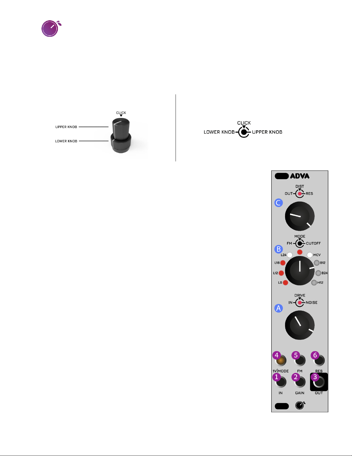
CUTOFF CLICK LOCK MODE:
When performing live with the ADVA, there may be situations where you want to disable the click
action of the Cutoff knob to prevent accidentally changing the filter mode.
Activating Click Lock Mode:
1. Simultaneously short press knobs Aand C.
2. The LED at the center of the LED ring will illuminate in white, indicating that the Cutoff click is
locked. In this mode, the module will not recognize presses on knob B.
Adjusting Filter Modes in Click Lock Mode:
•Even in Click Lock mode, you can adjust the filter modes:
oHold down the Cutoff knob (B).
oFor the next mode, short press the Cknob.
oFor the previous mode, short press the Aknob.
Deactivating Click Lock Mode:
•Again, simultaneously short press knobs Aand C.
•The central LED on the LED ring will no longer display in white. Note that, depending on the
Cutoff position, the LED might still illuminate in other colors.

PLUM AUDIO –ADVA 3U User Manuel, rev 1.1 (GREENY Firmware)
7
MCV –MODE CHANGE VIA CV:
The 1V | Mode input (4) has the flexibility to be reassigned for controlling the filter mode.
Activating MCV Mode:
1. Press and hold knobs Aand C for approximately 2 seconds.
2. Once the 1V | Mode input is designated to MCV:
•The corresponding LED on the ring will illuminate in white.
•The small LED inside the 1V | Mode jack will also activate.
In the MCV mode, the module accepts a CV range of 0-5V. You have the ability to 'offset' the modes by
manually transitioning between different modes.
Deactivating MCV Mode:
1. Repeat the activation process (press and hold knobs Aand Cfor about 2 seconds).
2. The LEDs associated with MCV will deactivate, signaling a reversion to its default V/OCT
assignment.
Note on MCV for ADVA:
ADVA employs swift switches to toggle between filter modes instantly. Consequently, there's no
crossfade between these modes. This design can occasionally produce a discernible "click" sound during
mode transitions, particularly at lower frequencies.
To mitigate or mask this 'click', ADVA is equipped with several tools. Here are general guidelines to help
you smooth out the transition:
1. Sequencer Synchronization: Utilize a sequencer to align mode changes with your rhythm. This
can mask the click within the rhythmic elements of your sequence.
2. Envelope Modulation of VCA: Modify the VCA using an envelope. By slightly increasing the
'Attack', you can soften the onset of the sound, potentially masking the click.
3. White Noise Generator: ADVA's internal white noise generator can be employed as a form of
dithering. This will introduce randomness that can effectively suppress the click.
4. Filter Modulation: Actively modulating the filter parameters can eliminate the click. When these
parameters are dynamic, the transient click becomes less noticeable.
5. Distortion Utilization: Engaging distortion and pushing it into the clipping range can overpower
the click, rendering it inaudible.

PLUM AUDIO –ADVA 3U User Manuel, rev 1.1 (GREENY Firmware)
8
DISABLE / ENABLE NOISE NORMALIZATION TO THE FM INPUT:
Release the mounting screws and take off the module from your case to access the small
slide switch, located on the left side of the module, on the central circuit board.
This switch will disconnect the noise normalization.
V/OCT CALIBRATION PROCEDURE:
The filter is designed to effectively track over 4 octaves. However, please note that it is not
temperature-stabilized.
Warm-Up: Before calibration, allow the module to warm up for approximately 20 minutes to ensure
optimal performance.
1. Cutoff Setting: Turn the cutoff knob to roughly the 10 o’clock position. The exact position isn't critical.
2. Resonance & FM Settings:
•Rotate the resonance knob to its maximum setting.
•Ensure no input signal or FM modulation CV is connected.
•Set the FM attenuverter to its midpoint (or, alternatively, disable noise normalization).
3. MCV Mode & Connection:
•Deactivate the MCV mode.
•Connect the note CV output from a properly-calibrated keyboard interface or MIDI-CV converter
to the 1V | MODE input.
4. Tone Monitoring:
•Listen to the tone emanating from the output. or alternatively, employ a tuner for precise
monitoring (You can use any filter mode).
5. V/OCT Trimmer Adjustment:
•On the modules's reverse side, locate the V/OCT trimmer.
•Adjust it until the musical intervals played on the keyboard match the output. The exact note
values aren't essential; however, when you play an octave on the keyboard, the output should
unmistakably sound like an octave.
6. Post-Calibration: Once the V/OCT calibration is complete, proceed with the LED ring calibration.

PLUM AUDIO –ADVA 3U User Manuel, rev 1.1 (GREENY Firmware)
9
LED Ring Calibration (Post V/OCT Calibration):
After completing V/OCT calibration, it is crucial to calibrate the LED ring for accurate visual feedback due
to changes in the values that the Cutoff knob sends to the microcontroller.
1. Entering LED Configuration Mode:
•Disconnect all modulation signals directed at the cutoff (both FM and V/OCT).
•Set the FM attenuverter to its mid-point position (or, alternatively, disable noise
normalization).
•Ensure the Click Lock mode is disabled.
2. Performing LED Ring Calibration:
•Set Minimum Value:
- Rotate the Cutoff knob to its minimum setting (counterclockwise) and press Knob A.
•Set Maximum Value:
- Rotate the Cutoff knob to its maximum setting (clockwise) and press Knob C.
ADJUST LED BRIGHTNESS:
LED brightness can be adjusted at any time as per your preference.
1. Entering LED Configuration Mode:
•Follow the same steps as above to enter LED Configuration Mode.
2. Adjusting Brightness:
•To increase brightness, rotate the Cutoff knob clockwise.
•To decrease brightness, rotate the Cutoff knob counterclockwise.
Notes:
•Within the initial 10% of the knob's rotation when turned fully counterclockwise, the cutoff
meter will be deactivated. In this setting, the LED ring will exclusively display the current filter
mode, MCV mode, and Click Lock mode.
•LED brightness directly impacts the module's power consumption:
oAt full brightness, the module draws 110mA from the +12V rail.
oAt 50% brightness, it draws only 85mA.
oAt minimum brightness, it draws less than 75mA.
Exiting LED Configuration:
To exit the LED Configuration Mode, give a short press on the Cutoff knob (B).

PLUM AUDIO –ADVA 3U User Manuel, rev 1.1 (GREENY Firmware)
10
ADVA IS AVAILABLE IN 3U/6HP AND 1U/22HP FORMATS WITH BLACK OR SILVER FRONT PANELS:
Table of contents
Other Plum Audio Recording Equipment manuals