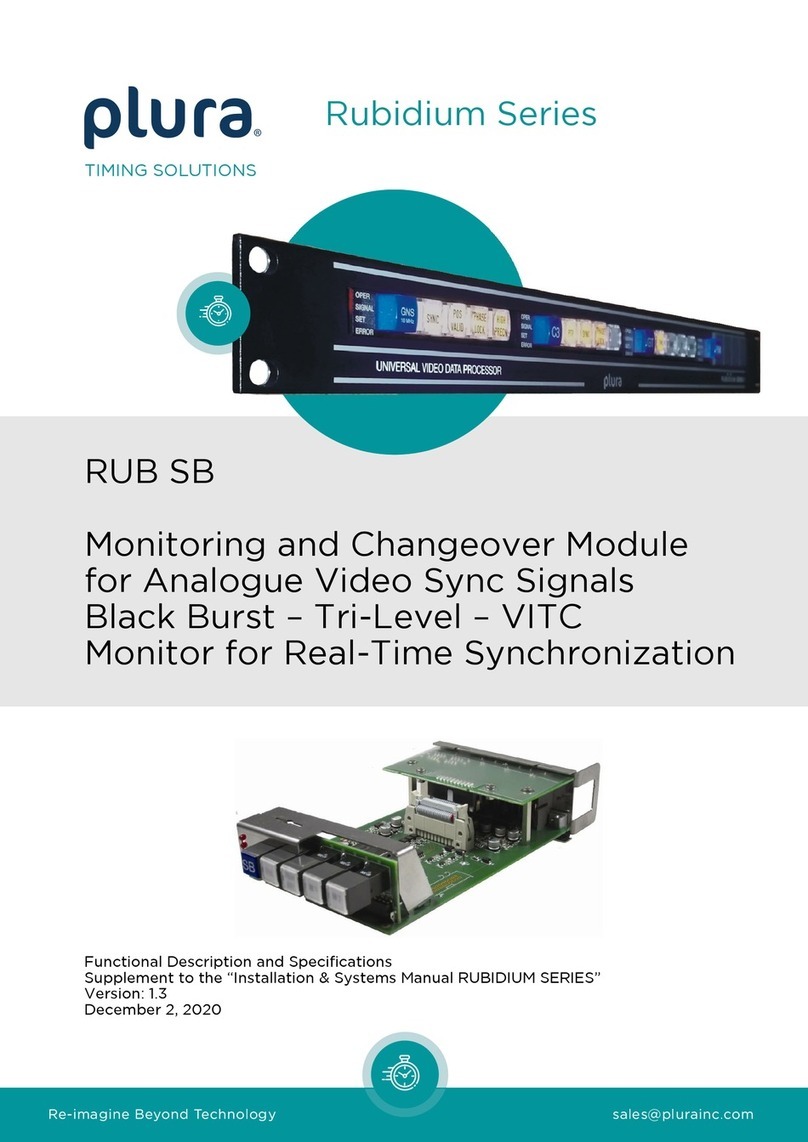
Plura RUBIDIUM Series User manual


Functional Description and Specifications RUB VL Page 3
CONTENTS
A1 REVISION HISTORY
A2 COPYRIGHT
A3 GENERAL REMARKS
1MODULE “VL” 6
1.1 GENERAL DESCRIPTION 6
1.2 REAR PANEL AND CONNECTORS 7
1.3 SPECIFICATIONS 9
1.4 FUNCTIONAL OVERVIEW 11
1.5 RS422 OUTPUT OR RS485(MTD) DISTRIBUTION 12
1.6 SOFTWARE UPDATE 13
2STATUS MONITOR 14
2.1 STATUS MONITOR BY THE IE MODULE 14
2.2 STATUS MONITOR BY A PC PROGRAM 14
2.3 SYSTEM STATUS 15
2.4 SIGNAL STATUS 16
2.5 STATUS OF FAN AND POWER SUPPLIES 18
3THE RUBIDIUM CONFIGURATION TOOLS 19
3.1 THE RUBIDIUM CONFIGURATION PC PROGRAM 19
3.2 THE RUBIDIUM SERIES HTTP SERVER 20
3.3 “FUNCTIONS“ 21
3.4 “KEYS“: KEYS, LAMPS, LEDS AND GPIS 22
3.5 “VL INPUT“: CONFIGURATION OF THE LTC INPUTS 25
3.6 “VL OUTPUT”: CONFIGURATION OF THE OUTPUTS 27
3.7 “LINK”: COMMUNICATION BETWEEN MODULES 32
3.8 “SYSTEM“: IDENTIFICATION, RESET, SNMP, FAN CONTROL 33
4TYPICAL APPLICATIONS 34
4.1 LTC(MTD): TIMER OR TIME ZONE DECODER 34
4.2 REAL-TIME LTC: FORMAT CONVERSION OF DATE 34
4.3 CONNECTING 3-WIRE OR 4-WIRE INTERFACE ANALOGUE CLOCKS 35
4.4 CONNECTING 2-WIRE INTERFACE ANALOGUE CLOCKS 36
4.5 CONNECTING THE 2-WIRE INTERFACE TO SC306T 37

Page 4 Functional Description and Specifications RUB VL
A1 Revision History
No.
Date
Subject
0.n
Preliminary documents, changes without notice.
1.0
March 15, 2006
First released document.
1.1
March 30, 2006
Internal jumper, RS422 or RS485 selection.
2.0
December 15, 2006
Revised.
2.1
June 04, 2007
Interface: Two new protocols.
Pulse: One new protocol.
GPI specifications: Revised.
2.2
November 27, 2007
Interface: Two new protocols.
2.3
December 18, 2007
Interface: Two new protocols.
Interface: If a protocol includes an address it is now possible to choose an address value.
Revised.
3.0
January 12, 2009
New hardware board 03.
TELEGRAM signals now at 24 V.
Revised.
3.1
October 06, 2009
New Impulse Telegram output modes.
New serial output protocols. Secondary address made available.
Revised.
3.2
February 22, 2010
Revised.
Function “Link” added.
3.3
April 30, 2010
Revised.
3.4
May 11, 2011
More information about cable lengths connecting analogue clocks.
4.0
June 06, 2011
Completely revised.
4.1
June 27, 2011
Interface: Two new protocols.
4.2
August 03, 2011
New output modes available: MTD Main 1 –3.
4.3
January 26, 2012
Interface: New protocols.
4.4
September 24, 2012
New hardware version with new location of jumpers –chapter “RS422 Output or RS485(MTD)
Distribution”.
“VL Output”: drop-down list “gain” revised.
4.5
September 3, 2019
Changed address of Plura Europe GmbH.
4.6
December 3, 2020
Re-formatted in new design.
Due to constant product development the features of this module are subject to change. The
current functional description always refers to the current software and the current
configuration tool.
You can download the latest version of the standard software from
https://www.plurainc.com.
Please be sure to use the latest configuration program after having done an update. You can
download the latest version from the address above.

Functional Description and Specifications RUB VL Page 5
A2 Copyright
Copyright © Plura Europe GmbH 2002-2020. All rights reserved. No part of this publication
may be reproduced, translated into another language, stored in a retrieval system, or
transmitted, in any form or by any means, electronic, mechanical, photocopying, recording, or
otherwise without the prior written consent of Plura Europe GmbH.
Printed in Germany.
Technical changes are reserved.
All brand and product names mentioned herein are used for identification purposes only and
are trademarks or registered trademarks of their respective holders.
Information in this publication replaces all previously published information. Plura Europe
GmbH assumes no responsibility for errors or omissions. Neither is any liability assumed for
damages resulting from the use of the information contained herein.
For further information please contact your local dealer or:
Plura Europe GmbH
Binger Weg 12
D- 55437 Ockenheim
Phone: +49 6725 918 006-70
Fax: +49 6725 918 006-77
E-Mail: info@plurainc.com
Internet: https://www.plurainc.com
A3 General Remarks
This manual is a supplement to the “Installation & Systems Manual RUBIDIUM SERIES”. Please
read the below listed chapters of the “Installation & Systems Manual RUBIDIUM SERIES”, as
these chapters are necessary for the safe and proper use of the Rubidium module “VL”.
•A3 Warranty,
•A4 Unpacking/Shipping/Repackaging Information,
•A5 Safety Instructions,
•A6 Certifications & Compliances,
•Plug-In a Module,
•Remove a Module.

Page 6 Functional Description and Specifications RUB VL
1 Module “VL”
1.1 General Description
The VL module is a signal distribution and amplifier with two separate LTC readers and four
independent LTC generators, four RS232 and RS4222 outputs and four output stages for
impulse telegram. All output signals are phase-locked to the LTC reference input.
LTC time and user bits (binary groups) can be read, processed and converted. The inde-
pendent outputs can be set up individually and can generate the processed/converted input
data with various output formats. For example, the Plura LTC(MTD) can be decoded and
converted to various output formats, so that external devices can display the individual stop
timers or time zone data. Impulse telegram outputs are available to control Plura analogue
clocks.
A PC or the RUB IE module is required for the configuration of this module.
The front panel label VL visibly identifies where each module is located. The serial number is
located on the bottom side of the lower circuit board of each module.
The standard hardware of this module has all of the following key features:
•“Hot Swapping“, i.e. it is possible to insert or remove a module without interrupting the
operation of other modules in this frame.
•Failure relay, connected to the FAIL_A and FAIL_B pins of the RLC connector at the rear of
the frame.
•RS232 and TC_link (RLC connector) interfaces to have access to the internal bus of the
chassis.
•Four programmable function keys, lamps and LEDs on the front panel (RUB1 version only).
•Flash memory containing the firmware, so configuration and updates are possible via a
PC connection. You can download the latest version of the program from:
https://www.plurainc.com.
•Two LTC readers.
•Four LTC generators.
•Four RS422 and four RS232 outputs.
•Four output stages for impulse telegrams, e.g. for controlling analogue clocks.
•Four programmable input or output GPI’s (General Purpose Interfaces) designed for
customer specific applications.

Functional Description and Specifications RUB VL Page 7
1.2 Rear Panel and Connectors
OUT 3
OUT 1
GPI
IN
8 . . . . . 1 8 . . . . . 1 8 . . . . . 1 8 . . . . . 1
OUT 2
VTR IN
LOOP
1 . . . . . 8 1 . . . . . 8 1 . . . . . 8
OUT 4
1 . . . . . 8
Pin assignments
IN
RJ45 jack
1: RS485_TRA_IN
2: RS485_TRB_IN
3: LTC_REF_ A
6: LTC_REF_ B
4: GND
5: n.c.
7: n.c.
8: n.c.
LOOP
RJ45 jack
1: RS485_TRA_IN
2: RS485_TRB_IN
3: LTC_REF_ A
6: LTC_REF _B
4: GND
5: n.c.
7: n.c.
8: n.c.
GPI
RJ45 jack
1: GND
2: GPI_1
3: GND
6: GPI_2
4: GND
5: GPI_3
7: GND
8: GPI_4
VTR IN
RJ45 jack
1: n.c.
2: n.c.
3: LTC_ VTR _A
6: LTC_ VTR _B
4: GND
5: n.c.
7: n.c.
8: n.c.
OUT 1
OUT 2
OUT 3
OUT 4
RJ45 jacks
1: RS422_T- or RS485_TRA_OUT –select by jumper
2: RS422_T+ or RS485_TRB_OUT –select by jumper
3: LTC_ OUT _A
6: LTC_ OUT _B
4: GND
5: TELEGRAM OUT
7: RS232_TxD
8: VCC12_OUT

Page 8 Functional Description and Specifications RUB VL
Signal descriptions
GND
Signal ground.
RS485_TRA_IN
RS485_TRB_IN
Balanced in- or outputs of an RS485 serial interface as the
source signal, hard wired between IN and LOOP connectors.
LTC_REF_A, LTC_REF_B
LTC_VTR_A, LTC_VTR_B
Balanced LTC (Linear Time Code) inputs.
GPI_1 … GPI_4
General Purpose Interface, may be used as input or output for
digital signals according to application.
RS485_TRA_OUT
RS485_TRB_OUT
Balanced in- or outputs of an RS485 serial interface. A
transceiver decouples these signals from the source signals.
RS422_T-/T+
Balanced RS422 output.
RS232_TxD
RS232 output.
LTC_OUT_A
LTC_OUT_B
Balanced LTC (Linear Time Code) output.
Connections: balanced use unbalanced use
toXLR3F
21
3
GND
LTC_OUT_B
LTC_OUT_A
toCinch/RCA/BNC LTC_OUT_A
GND
LTC_OUT_B
TELEGRAM OUT
Output of an impulse telegram, nominal level ≈ 12 V (Version 01 and
02) and ≈ 23 V (Version 03) without load.
The TELEGRAM OUT, VCC12_OUT and GND lines are used to control
analogue clocks of the Plura MTD system with a 4-wire interface.
TELEGRAM OUT and GND only are used to control analogue clocks of
the Plura MTD system with a 2-wire interface.
VCC12_OUT
12 VDC voltage output, 500 mA reversible fused (each output line), used
as the power supply for analogue clocks of the Plura MTD system.
Using VCC12_OUT output, please make sure not to exceed the total
power rating of the “Power Supply“ module.

Functional Description and Specifications RUB VL Page 9
1.3 Specifications
Input LTC reference (signals LTC_REF_A/LTC_REF_B at RJ45 IN)
Format
According to ANSI/SMPTE 12M-1-2008, balanced signals
Input impedance
18 k
Signal level
100 mVp-p - 5 Vp-p, auto-ranging
Frequency
19 - 33 frames/s
Input VTR LTC (signals LTC_VTR_A/LTC_VTR_B at RJ45 VTR IN)
Format
According to ANSI/SMPTE 12M-1-2008, balanced signals
Input impedance
18 k
Signal level
100 mVp-p - 5 Vp-p, auto-ranging
Frequency
1.6 - 2500 frames/s
LTC Output
Format
According to ANSI/SMPTE 12M-1-2008, balanced signals
Output impedance
< 50
Signal level
Adjustable:
balanced use: from –17 dBu/0,31 Vp-p to +13 dBu/9,8 Vp-p
unbalanced use: from –23 dBu/0,16 Vp-p to +7 dBu/4,9 Vp-p
RS422 Output
Format (electrical)
According to TIA/EIA-422 standard
Baud rates
Selectable 2400 to 115200 bps
RS232 Output
Format (electrical)
According to EIA/TIA-232 standard
Baud rates
Selectable 2400 to 115200 bps
TELEGRAM OUT
Signal
Output of an impulse telegram, nominal level ≈ 12 V (Version 01 and
02) and ≈ 23 V (Version 03) without load.
Maximum current
Fused by a 200 mA auto-recovery fuse each output stage.
A continuous current of up to 120 mA can be applied over the whole
specified operating temperature range.

Page 10 Functional Description and Specifications RUB VL
GPI_1, GPI_2, GPI_3, GPI_4
Input specification
Input “Low“: -15.0 to +0.7 V
Input “High“: +2.0 to +15.0 V
Impedance: ≈ 24 kΩ
Frequency: 0 - 1 kHz
Output specification
Open Collector output of an NPN Darlington transistor.
Internal 33k pull-up resistor.
Max. power dissipation: 250 mW.
“High“ state: 2.4 V (no load). For higher switching levels an
external pull-up to a positive power source of less than or equal to
24 VDC is needed, typically 1 kΩif connected to an external +5
VDC power source.
“Low“ state: output switched to GND.
Max. collector current: 200 mA DC, not fused.
Collector-emitter saturation voltage:
@20mA: typ. 0.72 V (0.85 V)
@100mA: typ. 0.9 V (1.1 V)
Frequency: 0 - 1 kHz.
Others
Operating voltage
15 - 30 VDC
Power consumption
Maximum 3.0 W (without load at the VCC12_OUT pins)
Weight
0.4 kg approx.
Dimensions
Standard circuit board (W x D): 100 x 160 mm/3.94 x 6.30 inch
Rear panel: Rub H1: 103 x 44 mm / 4.06 x 1.73 inch
Rub H3: 8HP, 3RU
Environmental charac-
teristics, operating
Temperature: 5 °C to 40 °C
Relative humidity: 30 % to 85 %, non-condensing
Environmental charac-
teristics, non-operating
Temperature: -10 °C to +60 °C
Relative humidity: 5 % to 95 %, non-condensing

Functional Description and Specifications RUB VL Page 11
1.4 Functional Overview
The standard functions of the module are:
•Reading and decoding LTC.
•Generating LTC: As “refresh“ of the read LTC,
as read LTC time + offset,
or as decoded MTD time.
•Sending RS232 and RS422 time and date information (for PCs, UMDs, video walls …).
Two different time offsets (± HH:MM:SS:FF) can be programmed. These can be added or
subtracted from the time information of the read LTCs (LTC_REF and LTC_VTR):
LTC_REF ± OFFSET1, LTC_REF ± OFFSET2, LTC_VTR ± OFFSET1, LTC_VTR ± OFFSET2.
This way VL generates four time bases internally which are synchronized to the external
LTC_REF. With an offset = 00:00:00:00 the read time information will be regenerated frame
accurately.
Furthermore, two independent free running counters are available as additional time
references. These counters can receive start values utilizing one of the configuration tools.
These counters can be controlled by external Start/Stop/Reset/Set signals.
If the module receives an LTC of the LTC(MTD) format, the following data of the LTC(MTD) will
be decoded: Timers A –F, real-time & date.
If the module receives an LTC which contains any known date format, this date can be
decoded.
Thus, different time information is available which can be generated as LTC time addresses,
LTC user bits, serial data strings in selectable protocols, and impulse telegrams to feed
analogue clocks. Any date encoded in the binary groups of the LTC input can be decoded
and converted into any binary group format of the outgoing LTC.
Proper decoding of the input data and conversion to any output signal requires a
configuration of the module utilizing one of the configuration tools:
1. For a proper decoding of LTC input data, the respective input format of the LTC must be
selected (see chapter "Configuration of the LTC Inputs").
2. Each output connector (OUT1 to OUT4) comprises LTC, serial interfaces, and an impulse
telegram. Each output signal can receive an individual set-up (see chapter "Configuration
of the Outputs").
PC programs are available for free: Configuration of the module = RubidiumConfig.exe,
status monitor = RubStatSE.exe.
The RUBIDIUM SERIES HTTP server, located in the Rub IE module, enables the configuration
of the module and offers a status monitor as well.

Page 12 Functional Description and Specifications RUB VL
1.5 RS422 Output or RS485(MTD) Distribution
Each output connector (OUT1 to OUT4) offers either an RS422 output or an RS485(MTD)
distribution at its pins 1 and 2:
RS422 output, signals RS422_T-, RS422_T+:
Serial data output, configuration by settings at “Interface” at the VL Output
function of a configuration tool. Data string is identical to the RS232 output.
RS485(MTD) distribution, signals RS485_TRA_OUT, RS485_TRB_OUT :
RS485 bus of the MTD Timer System, signals will be received/transmitted from/to
the RS485 at RJ45 IN and LOOP jack, whereas each RS485 at the RJ45 OUT jacks
is electrical decoupled from all other RS485 signals.
Select by jumpers located at the upper board of the VL module.
Jumper setting at latest version delivered since September 2012:
Rear
Front
2 1 4 3
422
485
OUT2
OUT1
OUT4
OUT3
422
Setting
485
Setting
Jumper setting at version delivered before September 2012:
Rear
Front
Position 1:
W5
W6
W7
W8
W1
W2
W3
W4
Position 2:
Position 1 = RS422
Position 2 = RS485(MTD)
OUT 1: W1 + W2
OUT 2: W3 + W4
OUT 3: W5 + W6
OUT 4: W7 + W8

Functional Description and Specifications RUB VL Page 13
1.6 Software Update
Software updates require a (windows operating system) computer and the “RUBIDIUM
CONFIGURATION“ program. You can download the latest version of the program from:
https://www.plurainc.com.
Please check the PC connector at your RUBIDIUM housing: there is an USB or RS232 (with a
DSUB9 connector) interface installed. You now need the same interface at your computer.
The new firmware should already be stored as a .tcf file at your computer.
Please now execute the following steps:
1. Connect your computer to the PC connector of that RUBIDIUM frame where the module
has been plugged.
In case of an RS232 interface: Use a straight (1:1) connection between the PC connector
at the RUBIDIUM frame and the RS232 of the computer.
In case of an USB interface: Use a USB A-B cable between your computer and the
RUBIDIUM frame.
Switch on the power of all units.
2. Execute “Rubidium Config.exe” on your computer. Select the “Port” according to the
interface (USB, RS232) you are using.
3. Select the module (unit 1, 2, 3 ...).
4. Select “Flash Update“ in the File menu.
5. Open the .tcf-file. Standard name: “Rubidium VL version.tcf“.
“version” stands for a revision no., e.g. 2.12.27.
Click the OK button, update starts. Click the OK button at the end.
6. Update is finished now. We recommend checking module’s configuration utilizing the
“RUBIDIUM CONFIGURATION“ program.
During the flash update the operation of the module stops!

Page 14 Functional Description and Specifications RUB VL
2 Status Monitor
2.1 Status Monitor by the IE Module
The RUBIDIUM SERIES HTTP server, located in the RUB IE module, offers a status monitor.
Please refer to the “Functional Descriptions and Specifications IE” manual for a detailed
description of how to access the RUBIDIUM SERIES system and how to open the RUBIDIUM
homepage.
•Click on VL on the left.
•Click on the button Status Monitor to open the “VL” status monitor.
Requirements:
•Please have Java Runtime Environment 1.6.0 or higher installed (for example download
at www.java.com).
•Java should be installed as a browser plug-in (a Windows installation will do this
automatically if you download Java from the source mentioned above).
•The Status Monitor works with all operating systems which support Java.
2.2 Status Monitor by a PC Program
The PC program RubStatSE.exe uses the PC interface (RS232 or USB) of the RUBIDIUM
housing. This program is part of the “Rubidium Series, config software” packet you can
download at:
https://www.plurainc.com.
Execute this program, select the COM port or USB connection and press the scan button to
get a list of the modules plugged to this housing. Select the module and press the connect
button.
Requirements:
•Please have Java Runtime Environment 1.6.0 or higher installed (for example download at
www.java.com).
•For a Windows operating system: Please follow the description of RubStatSE_Readme.txt.
•For a Linux operating system: Available on request.

Functional Description and Specifications RUB VL Page 15
2.3 System Status
The System page of the status monitor allows verifying the configuration of the inputs and
outputs.
Additionally, the "still status" indicates whether a "frozen” LTC output is currently being
generated.

Page 16 Functional Description and Specifications RUB VL
2.4 Signal Status
The Status page of the status monitor shows all the relevant status information.

Functional Description and Specifications RUB VL Page 17
ltc input
signal
“Yes“ if a signal can be read. “No“ if no signal can be read. This status is
similar to the function of the lamp “REF LTC”and “VTR LTC”, resp.
time
Time information (HH:MM:SS) of the read LTC.
user
User bits of the read LTC.
date source
Source for decoding the date: “reference ltc“ or “vtr ltc“ – depending on
configuration (see chapter „Configuration of the LTC Inputs“).
ltc(mtd) source
Source for decoding the MTD data: “reference ltc“ or “vtr ltc“ – depending
on configuration (see chapter „ Configuration of the LTC Inputs “).
ltc decoded data
date
If a valid date can be decoded, the date will be shown. “invalid“ will be shown if
no valid date is present.
ltc(mtd)
“valid“ will be shown if LTC of the LTC(MTD) format can be decoded.
“invalid“ will be shown if no LTC(MTD) is present.
time A
∙∙∙
time F
real time
Timer A –F and real-time are shown as decoded out of the MTD data.
These data will be valid only if “ltc(mtd) = valid“ is shown.
Note:
Displaying the MTD data serves for a quick check only and may not be com-
pared with the time representation of an MTD display. MTD displays evaluate
status information which influences the time representation. The status monitor
neglects this information. For example: “Negative” stop timer values will be
shown as positive values (24:00:00 –stop timer). Furthermore, the time accuracy
of the MTD timer values at the status monitor is less than one second.
ltc output lock status
pll lock current
All LTC outputs are synchronized to the LTC at input IN (LTC_REF).
A “yes“ or “no“ indicates the actual status of this phase
synchronization.
pll lock after reset
A “yes“ or “no“ indicates whether VL has been synchronized at least
once after power has turned on.
freq. divider, current
Information for service purposes: Current value of the frequency
divider for the internal frame clock.
freq. divider, nominal
Information for service purposes: Nominal value of the frequency
divider for the internal frame clock.
errors no sync
Error counter: Number of sync signal failures.
errors sync disturbance
Error counter: Number of sync signal disturbances.

Page 18 Functional Description and Specifications RUB VL
2.5 Status of Fan and Power Supplies
This module –as all configurable RUBIDIUM modules –is able to monitor the fan and power
supplies which are plugged to the same housing as “VL”.
Please refer to the document “Installation & Systems Manual RUBIDIUM SERIES” for a detailed
description.

Functional Description and Specifications RUB VL Page 19
3 The Rubidium Configuration Tools
3.1 The Rubidium Configuration PC Program
Please refer to the
“Installation & Systems Manual RUBIDIUM SERIES”
for a general description of this program and how to install it. In this document please notice
the following subchapters:
•Overview
•Installation
•Connection to RUBIDIUM SERIES Chassis
•Starting the Program
•Store, Load and Update the Configuration on your PC
•The “Profile” Tab: Store and Load Configurations on the Module
The program RUBIDIUM CONFIGURATION uses various tab cards. With one click on the
button Configure all available and currently activated tabs of this specific module are
displayed.
Any changes at a tab will immediately be stored at the module. If you enter a number or a text
press the tabulator key at the PC’s keyboard afterwards.

Page 20 Functional Description and Specifications RUB VL
3.2 The Rubidium Series HTTP Server
The RUBIDIUM SERIES HTTP server is located in the RUB IE module. A 10/100Base-T Ethernet
connection and a web browser allow accessing the RUBIDIUM system.
Please refer to the
“Installation & Systems Manual RUBIDIUM SERIES”
for a functional overview and for an installation description of this program. You will find the
chapter “The RUBIDIUM SERIES HTTP Server” and its subchapters:
•Overview, Connecting the IE Module
•IP Configuration, the Rubidium Homepage
•Access to a RUBIDIUM SERIES Module
•The “Profile” Page: Store and Load Configurations on the Module or on the PC
As soon as a communication to a single module has been established, the Configuration
page gives a list of all links to those pages which are actually enabled for a configuration.
Changes at a page will not be stored at the module automatically. At the bottom of each page
there are two buttons which should be used to store or load the module’s configuration:
Button Save To Module:
•Click on this button to transfer all settings on this page to the module.
Button Reload From Module:
•Click on this button to load the current configuration of the module.
VL
Every time you click on the blue button which indicates the module under confi-
guration a Reload will be done automatically.
Other manuals for RUBIDIUM Series
7
This manual suits for next models
1
Table of contents
Other Plura Control Unit manuals
Popular Control Unit manuals by other brands

PVA
PVA CA300 Operation manual

SMC Networks
SMC Networks LVP Series Operation manual

Texas Instruments
Texas Instruments TPS79301EVM user guide

Humandata
Humandata XP68-01-LX16 user manual

Sensitron
Sensitron STG/IN8-S2 instruction manual

ElMod
ElMod ThinkTank Tank Module PRO II Instructions for Assembly and Handling