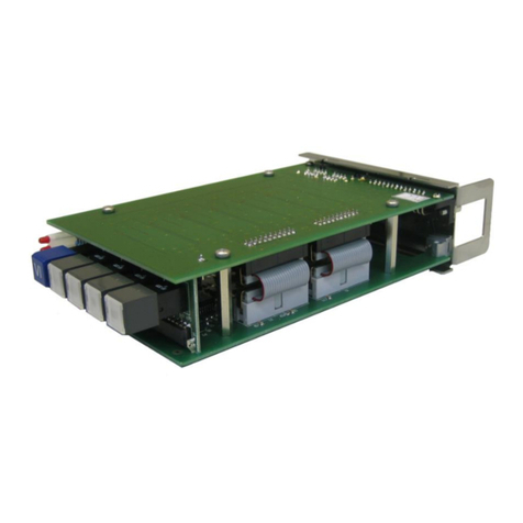
Functional Description and Specifications RUB SB Page 7
1 Module SB
1.1 General Description
This module can compare and contrast two sources of analogue video sync signals for
differences and real-time behaviour. Each source may consist of one or two signals, black
burst or tri-level, even mixed. If a black burst signal with VITC is connected, the VITC will be
monitored as well. Both sources should generate identical signals. In the event of a failure, SB
automatically switches to the other faultless source.
The SB module forms the central part of a redundant video sync system and/or redundant
VITC generator system, especially in a real-time application. Errors and failures of video or
VITC signals, any disturbances of real-time reference signals, time differences between the
sources, all these will be detected and can be indicated at a status monitor.
A PC or one of the RUB Ethernet modules (RUB IE or RUB PM) is required to configure this
module.
A front panel label SB visibly identifies RUB1 version modules. RUB3 version modules have this
label at the rear plate. A serial number is located on the bottom side of the lower circuit board
of each module.
The standard hardware of this module has all of the following key features:
•“Hot Swapping“, i.e. it is possible to insert or remove a module without interrupting the
operation of other modules in this frame.
•Failure relay, connected to the FAIL_A and FAIL_B pins of the RLC connector at the rear of
the frame.
•RS232 and TC_link (RLC connector) interfaces to have access to the internal bus of the
chassis.
•Four programmable function keys, lamps and LEDs on the front panel (RUB1 version only).
•Flash memory containing the firmware, so configuration and updates are possible via a
PC connection. You can download the latest version of the program from:
https://www.plurainc.com.
•2 x 2 analogue video inputs with VITC readers. Video and VITC signals are monitored.
•Inputs for signals of a real-time reference: PPS, time & date data string, 10
MHz signal.
These signals are monitored and will be used for various measurements.
•1 x 2 signal distribution of PPS and time & date data string.
•Changeover regarding the video signals utilizing latching relays.
•Alarm outputs indicating failures and warnings: lamps and LEDs (RUB1 version only),
GPOs, SNMP traps, and entries in the log file of an Ethernet module.


