manuals.online logo
Brands
  1. Home
  2. •
  3. Brands
  4. •
  5. Hubbell
  6. •
  7. Control Unit
  8. •
  9. Hubbell H-MOSS CU300HD User manual

Hubbell H-MOSS CU300HD User manual

Wiring Device-Kellems
Hubbell Incorporated (Delaware)
Shelton CT. 06484
1-800-288-6000
www.hubbell-wiring.com
®
English Français Español
Installation Instructions Directives de montage Instrucciones de instalación
PD2573 (Page 1) 03/16
CU300HD/ CU300HDU
CONTROL UNIT, HEAVY DUTY MODULEDECOMMANDECU300HD/
CU300HDU SERVICE INTENSIF MÓDULO DE CONTROL CU300HD/
CU300HDU USO RUDO
SPECIFICATIONS
• Input Voltage: 100 - 277V~ 50/60 Hz, 20A.
• Output Voltage: 24VDC, Class 2, Short Circuit Protected
250mA up to104°F (40°C).
100mA up to 149°F (65°C).
• Relay Contact Ratings: 20A, 100V to 277V AC, 50/60 Hz. 1 HP at
120V AC or 2 HP at 240 / 277V AC.
• Mounts inside or outside junction box.
• Use 1/2" conduit locknut to secure unit to junction box or to lighting
xture.
• Powers up to 6 sensors. See maximum current limits above.
• UL2043 Plenum rated. Acceptable for use in environmental air
handling spaces (plenums) other than ducts per NEC®article
300.22 (C).
Important Notes: Please read before installing.
CAUTION: RISK OF ELECTRICAL SHOCK.
•Disconnect power before installing. Never wire energized electrical
components.
• Forinstallationbyaqualiedelectricianinaccordancewithall
local and national electrical codes.
• Use Copper Conductors Only.
• Check to see that the device type and ratings is suitable for the
application.
• Do not install if product has any visible damage.
• If moisture or condensation is evident, allow the product to dry
completely before installation.
• Operate between -40°F (-40 °C) and 149°F(65 °C). Below 32°F
(0°C) must use suitably rated non-metallic enclosure. 0% to 90%
humidity, non-condensing.
INSTALLATION
1. Turn power OFF at the service panel.
2. Use #6-32 pan head screws or ½ “ conduit locknut to secure unit
if mounting inside junction box.
3.
Connect the unit to the circuit as shown in the wiring diagram Fig. 1.
Note: The maximum length of #18-22 AWG wire between the
control unit and associated sensors should not exceed 200ft.
CU300HD/ CU300HDU Manual ON/OFF Operation
4a Automatic ON (occupancy) conguration and operation:
Thedeviceisfactoryconguredtooperate in automatic ONmode.
SPÉCIFICATIONS
• Tension d'entrée : 100 à 277 Vca, 50/60 Hz
• Tension de sortie : 24 Vcc, (classe 2), protégé contre les courts-
circuits.
250 mA jusqu'à 40 °C; 100 mA jusqu'à 65 °C.
• Valeurs nominales des contacts du relais : 20 A, 100 à 277 Vca
50/60 Hz. 1 HP à 120 Vca ou 2 HP à 240 / 277 Vca.
• Montage à l'intérieur ou à l'extérieur d'une boîte de dérivation.
• Utiliseruncontre-écroude13mmpourconduitpourxerlemodule
à la boîte de dérivation ou au luminaire.
• Alimente jusqu'à 6 capteurs. Voir les limites de courant maximales
ci-haut.
• Homologué UL2043 pour plénum. Convient aux aires de distribution de
l’air (plénums) autres que les conduits selon NEC®article 300.22 (C).
Remarques importantes - Lire avant de procéder au montage
ATTENTION - RISQUE DE CHOC ÉLECTRIQUE.
• Débrancher le circuit avant de procéder au montage. Ne jamais câbler
des composants électriques dans un circuit sous tension.
• Doitêtreinstalléparunélectricienqualiéconformémentauxcodes
de l'électricité nationaux et locaux.
• Employer uniquement des conducteurs en cuivre.
• S'assurer que les caractéristiques nominales de ce dispositif
conviennent à l'application.
• Ne pas monter l’appareil si l’on y décèle des dommages apparents.
• Lire et comprendre les directives de montage avant d'entreprendre
les travaux.
• En présence d’humidité ou de condensation, laisser le produit sécher
complètement avant de l’installer.
• Température d’exploitation :
-40 °C et 65 °C.
Sous 0 °C, utiliser un boîtier
non métallique approprié. Humidité : 0 % à 90 %, sans condensation.
MONTAGE
1. Couper l'alimentation au niveau du coffret de branchement.
2. Utiliser des vis 6x32 à tête cylindrique ou un écrou de blocage pour
conduitde13mmpourxerlemoduleàl'intérieurd'uneboîtede
dérivation.
3. Raccorder l'unité au circuit conformément au schéma de câblage
de la Fig. 1.
REMARQUE-Lalongueurmaximaledelnº18-22entrelemodule
de commande et les capteurs associés ne doit pas dépasser 61 m.
Fonctionnement ON/OFF manuel du CU300HD/ CU300HDU
4a Fonctionnement et conguration automatiques ON (présence)
ESPECIFICACIONES
• Voltaje de entrada: 100 a 277 V~, 50/60 Hz
• Voltaje de salida: V=24, (clase 2), protegida contra cortocircuitos.
250 mA hasta 40 °C; 100 mA hasta 65 °C.
• Características nominales de los contactos de relé: 20 A, 100 a
277 V~ 50/60 Hz. 1 HP a 120 V~ o 2 HP a 240 / 277 V~.
• Montaje adentro o afuera de una caja de derivación.
• Usarunacontratuercade13mmdeconductoparajarelmódulo
a la caja de derivación o el artefacto.
• Alimenta hasta 6 sensores. Ver limitas máximas de corriente arriba.
• Homologado UL2043 para cámara de distribución. Aceptable para
uso en espacios de procesamiento de aire (cámaras de distribución)
distintos de ductos según el artículo 300.22 (C) de NEC®.
Notas importantes: Lea antes de la instalación.
¡CUIDADO! - RIESGO DE CHOQUE ELÉCTRICO.
• Desconectar la corriente antes de la instalación. No conectar
nunca componentes eléctricos en un circuito energizado.
• Paraserinstaladaporunelectricistacalicado,deacuerdocon
los códigos eléctricos nacionales y locales.
• Utilizar solamente conductores de cobre.
• Asegurarse de que las características nominales del dispositivo
sean apropiadas para la aplicación.
• No instalar si se observa cualquier daño en el producto.
• Leer y comprender las instrucciones antes de instalar.
• Si hay señales de humedad o condensación, deje secar
completamente el producto antes de la instalación.
• Opere entre -40°C y 65 °C. Bajo 0 °C, utilizar una caja no metálica
apropiada. 0% a 90% de humedad, sin condensación.
INSTALACIÓN
1. Cortar la alimentación de energía en el tablero de servicio.
2. Usar tornillos 6x32 de cabeza chaneada o contratuerca de
conductode13mmparajarlaunidad,sisemontadentrodela
caja de derivación.
3. Conectar la unidad al circuito como se muestra en el diagrama de
cableado de la Fig. 1.
Nota-Lalongitudmáximadecablenº18-22entreelmodulode
control y les detectores asociados no debería exceder 61 m.
Operación y conguración manual ON/OFF - CU300HD/
CU300HDU
4a Conguración y operación en ON automático (presencia)
Eldispositivoestáconguradoenfábricaparaoperarenmodo
HUBBELL DE MEXICO garantiza este producto, de estar libre de defectos en
materiales y mano de obra por un período de un año a partir de la fecha de su
compra. HUBBELL reparará o reemplazará a su juicio el producto en un plazo
de 60 días. Esta garantía no cubre desgastes por uso normal o daños ocasio-
nados por accidente, mal uso, abuso o negligencia. El vendedor no otorga otras
garantías salvo lo expresado arriba y excluye expresamente daños incidentales
o consecuenciales. ESTA GARANTÍA ES VÁLIDA SÓLO EN MÉXICO.
HUBBELL DE MÉXlCO, S.A. DE C.V.
Av. Insurgentes Sur # 1228 Piso 8, Col. Tlacoquemecatl del Valle
México, 03200 D.F. Tel. (55) 9151-9999
PD2573 (Page 2) 03/16
Connect red, black, and blue low voltage wires to
corresponding wires to sensors and cap the orange wire.
The load will turn ON automatically when motion is detected and will
turn OFF when sensors time out.
4b Manual ON (vacancy) conguration and operation:
CongurethedeviceformanualONoperationbycuttingtheyellowwire
loop and cap the ends separately. Connect red, black, and blue low
voltage wires to corresponding wires to sensors. Connect the orange
wire to a momentary pushbutton switch. The momentary pushbutton
switch (user supplied) needs to be connected between the orange
manual ON wire and the red +24VDC wire.
Turn the loads ON manually by pressing the momentary switch.
Motion must be detected within 30 seconds of pressing the momentary
switch to keep the load ON.
If the load turns OFF automatically, it can be turned back on without
pressing the momentary switch if motion is detected within 30 seconds.
Pressing the manual switch while the load is ON turns the load OFF
regardless of sensor status.
5 Turn power ON at service panel.
ON automático. Conectar los alambres rojo, negro y
azul de bajo voltaje a los alambres correspondientes
de los sensores y tapar el alambre anaranjado.
La carga se encenderá (ON) automáticamente al detectar
movimiento y se apagará (OFF) cuando los sensores lleguen a
apagado temporizado.
4b.Conguración y operación en ON manual (desocupado)
 CongurareldispositivoparaoperaciónONmanualcortandoel
bucle de alambre amarillo y tapar los extremos separadamente.
Conectar los alambres rojo, negro y azul de bajo voltaje a los
alambres correspondientes de los sensores. Conectar el alambre
anaranjado a un interruptor pulsador provisional. El interruptor
pulsador provisional (suministrado por el usuario) deber ser
conectado entre el alambre anaranjado de ON manual y el
alambre de +V=24.
Encender (ON) las cargas manualmente presionando el
interruptor provisional.
Se debe detectar movimiento dentro de los 30 segundos después de
presionar el interruptor provisional para mantener la carga en ON.
Si la carga se apaga (OFF) automáticamente, se puede volver
a encender sin presionar el interruptor provisional si se detecta
movimiento dentro de los 30 segundos.
Al presionar el interruptor manual mientras la carga está en ON,
se apaga (OFF) la carga sin importar el estado del sensor.
5. Alimentar de nuevo la energía en el tablero de servicio.
 Cedispositifestconguréenusinepourfonctionner
enmodeautomatique(ON).Raccorderleslsbasse
tensionrouge,noiretbleuauxlscorrespondantsdescapteurs
etobturerlelorange
.
La charge se met à ON automatiquement dès la détection de
mouvement et à OFF une fois la temporisation des capteurs écoulée.
4b
Fonctionnement et conguration manuels ON (absence)
CongurerledispositifpourunfonctionnementmanuelONencoupantla
boucleduljauneetenobturantlesextrémitésséparément.
Raccorder
leslsbassetensionrouge,noiretbleuauxlscorrespondantsdes
capteurs
.Raccorderlelorangeàuninterrupteuràbouton-poussoirà
contact momentané. L'interrupteur momentané (fourni par le client) doit
êtreraccordéentrelelorangeONmanueletlelrougede+24Vcc.
Remettre les charges sous tension ON manuellement en appuyant sur
l'interrupteur momentané.
La détection de mouvement doit se faire dans les 30 secondes après
avoir enfoncé l'interrupteur momentané pour que la charge demeure
à ON.
Lorsque la charge passe à OFF automatiquement, il est possible qu'elle
bascule à ON sans qu'on ait à appuyer sur l'interrupteur momentané à
la condition qu'il y ait détection de mouvement dans les 30 secondes.
Appuyer sur l'interrupteur manuel lorsque la charge est à ON pour la
faire basculer à OFF peu importe l'état du capteur.
5
Remettre le circuit sous tension à partir du coffret de branchement.
Ground / MALT / Tierra LOAD
CHARGE
CARGA
Override Switch (Optional)
Commutateur d'annulation de priorité (optionnel)
Interruptor de anulación de prioridad (optativo)
CU300HD/ CU300HDU
Red (+24VDC) / Rouge / Rojo
Black / Noir / Negro
Momentary Switch (Optional)
Interrupteur momentané (optionnel)
Interruptor provisional (optativo)
Blue / Bleu / Azul
Yellow Loop / Boucle jaune / Lazo amarillo
White / Blanc / Blanco
Black / Noir / Negro
Red / Rouge / Rojo
Orange / Orange / Naranja
Hot Line In
/
Phase Ligne d'entrée
/
Vivo Línea de entrada
Neutral / Neutre / Neutro
Fig. 1
English Français Español
Need Help? www.hubbell-wiring.com or call Technical Service at 1.475.882.4820.
Besoin d’aide? Visitez www.hubbell-wiring.com ou appelez le Centre d’assistance technique de Hubbell au 1.475.882.4820.
¿Necesita ayuda? Visite www.hubbell-wiring.com o llame al Servicio técnico al +1.475.882.4820.

This manual suits for next models

1

Other Hubbell Control Unit manuals

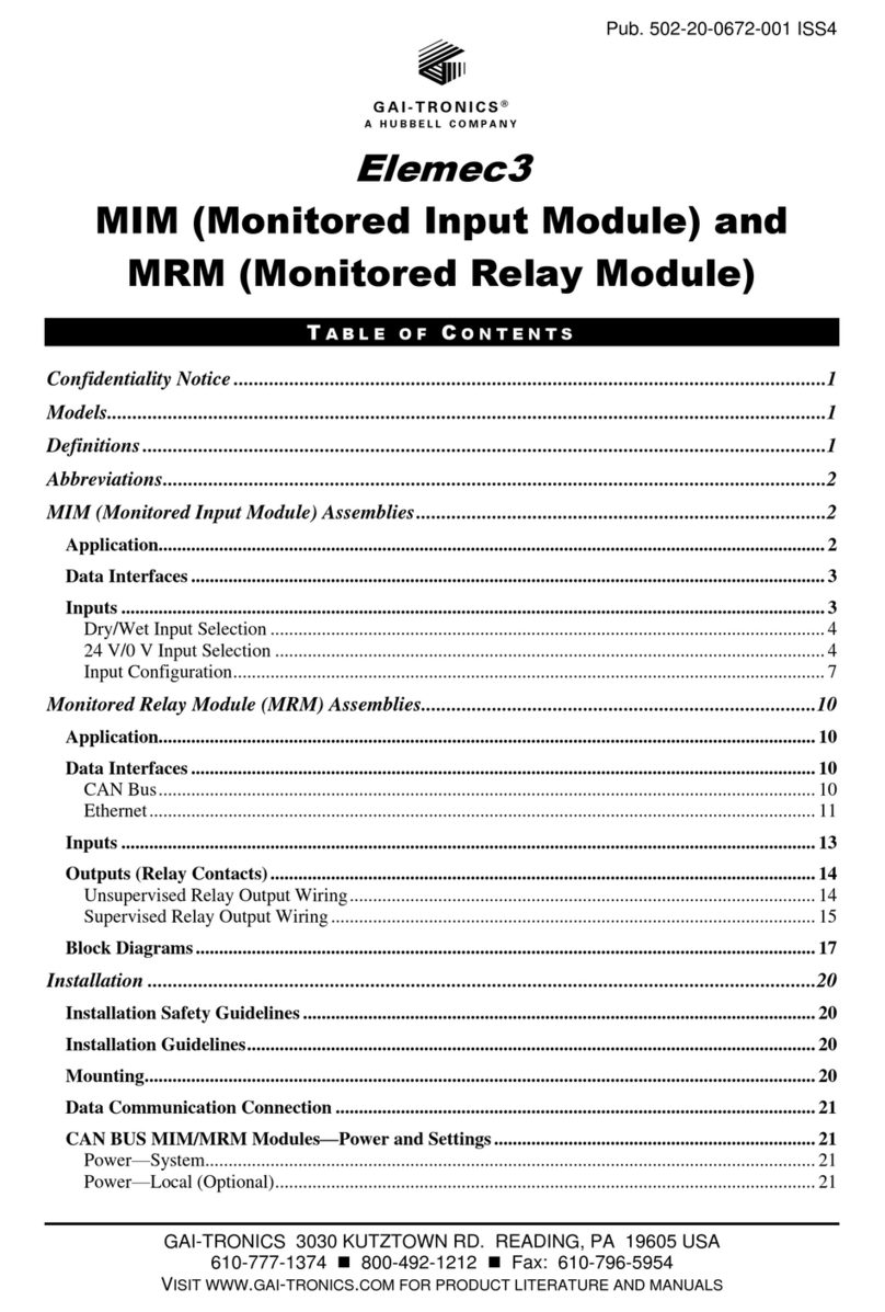
Hubbell GAI-Tronics Elemec3 MIM User manual

Hubbell

Hubbell GAI-Tronics Elemec3 MIM User manual

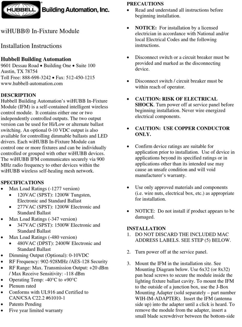
Hubbell wiHUBB User manual

Hubbell

Hubbell wiHUBB User manual

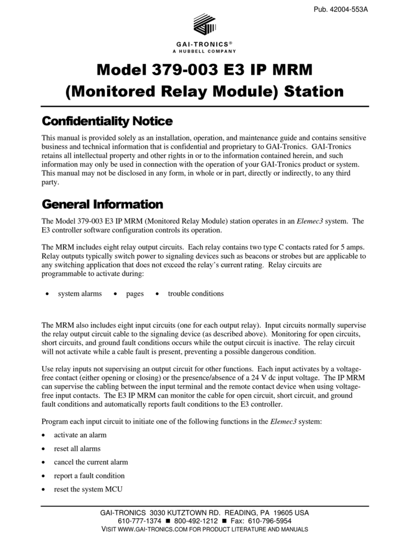
Hubbell GAI-TRONICS 379-003 IP MRM User manual

Hubbell

Hubbell GAI-TRONICS 379-003 IP MRM User manual

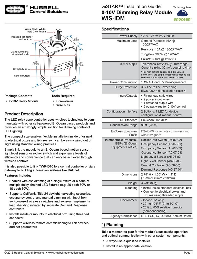
Hubbell wiSTAR WIS-IDM User manual

Hubbell

Hubbell wiSTAR WIS-IDM User manual

Hubbell GAI-TRONICS 379-003 E3 IP MRM User manual

Hubbell

Hubbell GAI-TRONICS 379-003 E3 IP MRM User manual

Hubbell GAI-TRONICS XCP0020A User manual

Hubbell

Hubbell GAI-TRONICS XCP0020A User manual

Hubbell GAI-TRONICS HUBBCOM GRC600SS User manual

Hubbell

Hubbell GAI-TRONICS HUBBCOM GRC600SS User manual

Hubbell GAI-TRONICS 378-003 E3 IP MIM User manual

Hubbell

Hubbell GAI-TRONICS 378-003 E3 IP MIM User manual

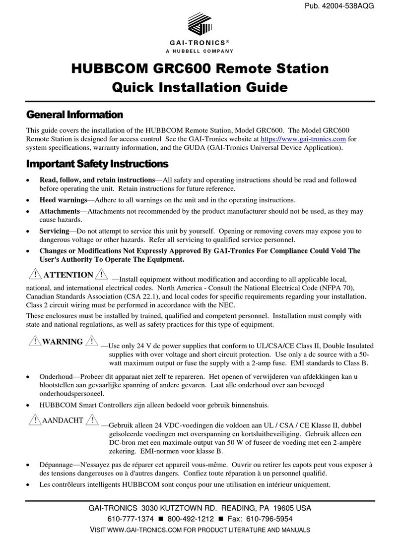
Hubbell GAI-TRONICS HUBBCOM GRC600 User manual

Hubbell

Hubbell GAI-TRONICS HUBBCOM GRC600 User manual

Hubbell GAI-TRONICS E3 User manual

Hubbell

Hubbell GAI-TRONICS E3 User manual

Hubbell Gai-Tronics 12504-009 User manual

Hubbell

Hubbell Gai-Tronics 12504-009 User manual

Hubbell GAI-TRONICS HUBBCOM GRC600 User manual

Hubbell

Hubbell GAI-TRONICS HUBBCOM GRC600 User manual

Popular Control Unit manuals by other brands

Kohler K-528 installation guide

Kohler

Kohler K-528 installation guide

Lenze 9350 operating instructions

Lenze

Lenze 9350 operating instructions

Ebyte E108-GN Series user manual

Ebyte

Ebyte E108-GN Series user manual

Nakanishi iSpeed3 Operation manual

Nakanishi

Nakanishi iSpeed3 Operation manual

Maker Factory ARDUINO MAKEVMA312 user manual

Maker Factory

Maker Factory ARDUINO MAKEVMA312 user manual

Pentek 4200A operating manual

Pentek

Pentek 4200A operating manual

Atco ADAS-500 user manual

Atco

Atco ADAS-500 user manual

SonicWALL NSA 250M series installation guide

SonicWALL

SonicWALL NSA 250M series installation guide

wtw IQ SENSOR NET MIQ/R6 operating manual

wtw

wtw IQ SENSOR NET MIQ/R6 operating manual

Fermax 2911 manual

Fermax

Fermax 2911 manual

Ebyte E70 Series user manual

Ebyte

Ebyte E70 Series user manual

Spectrum Digital TMS320C6416 DSK Technical reference

Spectrum Digital

Spectrum Digital TMS320C6416 DSK Technical reference

Siemens SIMOTION Function manual

Siemens

Siemens SIMOTION Function manual

BECKWITH ELECTRIC M-6200A Application guide

BECKWITH ELECTRIC

BECKWITH ELECTRIC M-6200A Application guide

Allen-Bradley SLC 500 DeviceNet user manual

Allen-Bradley

Allen-Bradley SLC 500 DeviceNet user manual

Ebyte E107-SC01 Series user manual

Ebyte

Ebyte E107-SC01 Series user manual

ERHARD NON SLAM operating instructions

ERHARD

ERHARD NON SLAM operating instructions

Zimmer ZR1000-A Series Installation and operating instructions

Zimmer

Zimmer ZR1000-A Series Installation and operating instructions

manuals.online logo
manuals.online logoBrands
  • About & Mission
  • Contact us
  • Privacy Policy
  • Terms and Conditions

Copyright 2025 Manuals.Online. All Rights Reserved.