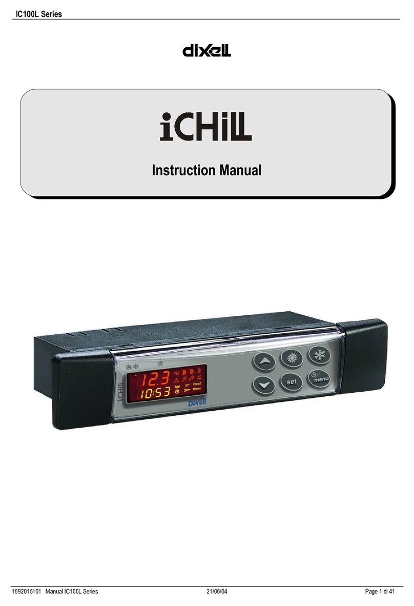
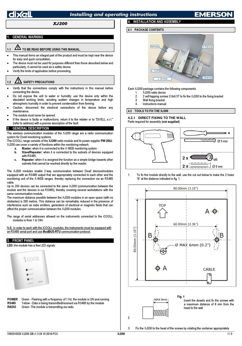
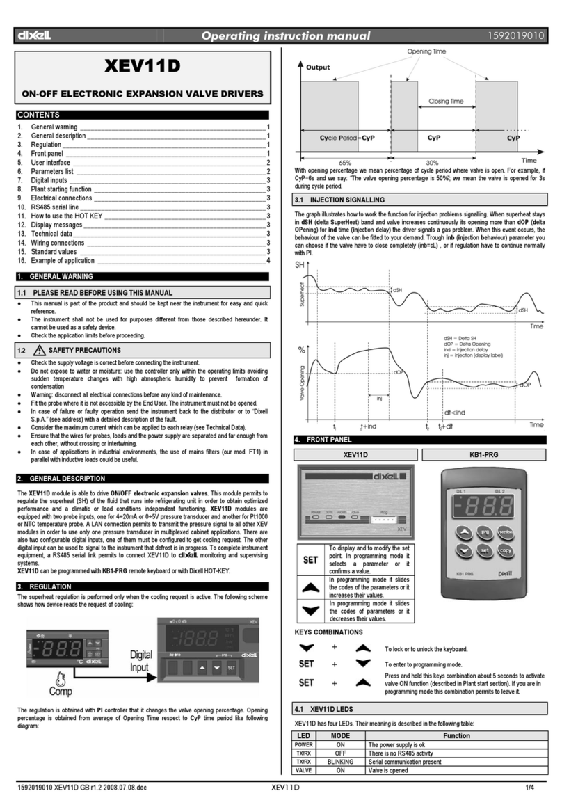
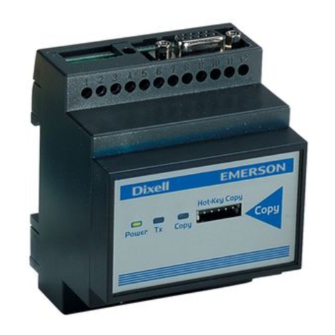
dixell ichill IC260L User manual

IC200L Series
User manual
dIXEL

INDEX
1GENERAL ADVICE 7
2GENERAL FEATURES 8
2.1 MAIN FUNCTION 8
3IC200 L TABLE OF THE FEATURES 10
4USER INTERFACE 11
4.1 FUNCTION OF THE LEDS OF THE KEY BUTTONS 11
4.2 USE OF THE LED ON THE MODELS VI620 - VI620S REMOTE PANELS 13
4.3 USE OF THE LED ON THE MODELS VI820 - VI820S REMOTE PANELS 13
4.4 KEY FUNCTION 14
4.5 KEY COMBINANTION 15
4.6 LED AND ICONS 15
4.7 DISPLAY AND ICONS 16
4.8 MEANING/ FUNCTIONNING OF THE BOTTOM DISPLAY LED 17
5REMOTE TERMINAL 17
6FIRST INSTALLING 17
6.1 ON BOARD CLOCK (OPTIONAL) 17
6.2 RTC SETUP 17
7WIRING CONNECTIONS 18
7.1 HARDWARE RESOURCES FOR IC260L - IC280L MODELS 18
7.2 HARDWARE RESOURCES FOR IC261L - IC281L MODELS 18
7.3 ANALOG INPUTS NTC – PTC PROBES 19
7.4 DIGITAL INPUTS 19
7.5 ANALOG INPUT FOR PRESSURE TRANSDUCER PP30 (4 ÷ 20MA SIGNAL) 19
7.6 ANALOG INPUT FOR PRESSURE RATIOMETRIC TRANSDUCER PPR30 (0 ÷ 5V SIGNAL) 20
7.7 PWM OUTPUT FOR CONDENSING FAN SPEED CONTROL 20
7.8 FAN CONDENSING CONTROL: 0 ÷ 10VDC OUTPUTS 21
7.9 FAN CONDENSING CONTROL WITH 4÷20MA OUTPUT 21
7.10 PROPORTIONAL OUTPUTS 0 ÷ 10V DUMPER CONTROL 22
7.11 PROPORTIONAL OUTPUTS CONFIGURED FOR AUX RELAY CONTROL 22
7.12 HOT KEY 64 CONNECTION 23
7.13 XJ485 CONNECTION 23
7.14 REMOTE PANELS VI620 – VI820 24
8ANALOG AND DIGITAL OUTPUT CONFIGURATION 24
8.1 ANALOG INPUT PB1 - PB2 - PB7 - PB8 - PB9 - PB10 24
8.2 ANALOG INPUT CONFIGURATION PB3 - PB4 - PB5 - PB6 25
8.3 DIGITAL INPUT CONFIGURATION ID1 – ID18 25
8.4 DIGITAL OUTPUT (RELAY) CONFIGURATION RL1- RL14 26
8.5 CONDENSER PROPORTIONAL CONTROL CONFIGURATION (2 OUTPUTS) 27
8.6 PROPORTIONAL OUTPUT CONFIGURATION 0 ÷ 10 VDC (4 OUTPUTS) 27
8.7 OTHER OUTPUTS 27
9TABLE OF THE PARAMETERS 28
10 PROGRAMMING WITH THE “HOT KEY 64” 42
10.1 DOWNLOAD: HOW TO PROGRAM AN INSTRUMENT WITH A PROGRAMMED “HOT KEY” 42
10.2 UPLOAD: HOW TO PROGRAM A “HOT KEY” WITH THE PARAMETERS OF THE INSTRUMENT 42
11 PROGRAMMING USING THE KEYBOARD 42
11.1 PASSWORD DEFAULT VALUES 42
11.2 ENTER THE PR1 - PR2 - PR3 PROGRAMMING LEVELS 43
11.3 HOW TO CHANGE A PARAMETER VALUE 43
11.4 CHANGE THE PASSWORD VALUE 43
11.5 ENTER THE PROGRAMMING LEVEL PR1 43
11.6 ENTER THE PROGRAMMING LEVEL PR2 44
11.7 ENTER THE PROGRAMMING LEVEL PR3 44
11.8 MOVE A PARAMETER LEVEL FROM PR2 TO PR1 45
11.9 MOVE A PARAMETER FROM PR3 TO PR2 TO PR1 45
11.10 VISIBILITY AND PARAMETER VALUE LOCKED 45
11.11 PROGRAMMING: DIGITAL INPUT AND OUTPUT POLARITY 45
11.12 CHANGE THE POLARITY OF THE DIGITAL INPUTS-OUTPUTS 46
12 SELECTION AND START OF THE RUNNING MODE 46
12.1 SELECT THE CHILLER OR THE HEAT PUMP MODE 46
12.2 CHANGE OVER 46

12.3 CHILLER – HEAT PUMP FUNCTIONING MODE 47
12.4 KEYBOARD SELECTION 47
12.5 ANALOG INPUT SELECTION 47
13 UNIT START- STOP 47
13.1 START – STOP AND STAND- BY FROM KEYBOARD 47
13.2 UNIT START- STOP FROM DIGITAL INPUT 47
14 DISPLAY LAYOUT 48
14.1 HOW TO SHOW THE MEASUREMENT LIST. 48
14.2 SHOW THE CIRCUIT 1 OR 2 48
15 CUSTOM DISPLAY 48
15.1 DEFAULT READ - OUT OF THE TOP DISPLAY 48
15.2 DEFAULT READ - OUT OF THE BOTTOM DISPLAY 50
15.3 FORCED READ - OUT OF THE TOP AND BOTTOM DISPLAY 50
15.4 DEFAULT DISPLAY READ - OUT OF THE REMOTE PANELS VI620S AND VI820S 51
15.5 DEFAULT DISPLAY READ - OUT OF THE REMOTE PANELS VI620S AND VI820S 51
16 DISPLAY INFORMATION 51
16.1 SHOW THE SET POINT VALUE 51
16.2 MODIFY THE SET POINT 51
16.3 SHOW THE ACTIVE SETPOINT DURING ENERGY SAVING OR DYNAMIC SETPOINT 51
16.4 DISPLAY IN REMOTE OFF 52
16.5 DISPLAY IN MOTOCONDENSING CONFIGURATION 52
17 FUNCTION MENU “ M” KEY 52
17.1 ALARM LIST: SHOW AND RESET 52
17.2 COMPRESSOR OVERLOAD ALARM RESET 52
17.3 COMPRESSOR OVERLOAD PASSWORD. 53
17.4 ALARM LOG LIST 53
17.5 ERASE THE ALARM LOG LIST 53
17.6 PASSWORD VALUE OF THE ALARM LIST 53
17.7 DISABLE – ENABLE A SINGLE CIRCUIT 53
17.8 READ-OUT OF A CIRCUIT NOT ENABLED 53
17.9 ENABLE OR DISABLE A SINGLE COMPRESSOR 53
17.10 READ-OUT OF A COMPRESSOR NOT ENABLED 54
17.11 READ-OUT OF THE COMPRESSOR DISCHARGE TEMPERATURE PROBE 54
17.12 READ-OUT OF THE RUNNING HOURS 54
17.13 RESET THE RUNNING HOUR 54
17.14 READ-OUT OF THE COMPRESSOR STARTS-UP 54
17.15 RESET THE STARTS-UP NUMBER 54
17.16 READ-OUT OF THE PROPORTIONAL OUTPUT PERCENTAGE OF THE CONDENSER FAN CONTROL 55
17.17 READ-OUT OF THE FOUR PROPORTIONAL OUTPUT 55
17.18 READ-OUT OF THE TIME COUNTING TO THE NEXT DEFROST 55
17.19 READ-OUT OF THE PROBES CONFIGURED TO CONTROL AN AUXILIARY OUTPUT RELAY 55
17.20 HOW TO DISPLAY THE TEMPAERATURE OF THE INTERNAL TEMPERAURE SENSOR OF THE REMOTE
TERMINALS 1 OR 2 55
18 ENERGY SAVING 56
18.1 ENERGY SAVING FROM DIGITAL INPUT 56
18.2 ENERGY SAVING TIME TABLE WITH RTC 56
18.3 RTC DAILY TIME TABLE PROGRAMMING 56
18.4 ENERGY SAVING OR UNIT ON/OFF ACTIVATION WITH RTC PROGRAMMING 56
19 DYNAMIC SETPOINT 57
19.1 DYNAMIC SETPOINT GRAPH 58
20 AUXILIARY RELAYS 59
20.1 AUXILIARY RELAY WITH DIRECT ACTION 59
20.2 AUXILIARY RELAY WITH INVERSE ACTION 59
21 COMPRESSOR THERMOREGULATION 59
21.1 THERMOREGULATION PARAMETER DESCRIPTION 59
22 SELECTION OF THE KIND OF THERMOREGULATION 60
22.1 GRAPH OF THE COMPRESSOR THERMOREGULATION IN CHILLER 60
22.2 GRAPH OF THE COMPRESSOR THERMOREGULATION IN HEAT PUMP 61
22.3 GRAPH NEUTRAL ZONE COMPRESSOR CONTROL 61
22.4 GRAPH PROPORTIONAL INTEGRAL COMPRESSOR REGULATION CONTROL 61
23 THERMOREGULATION OF THE ANTI FREEZE, INTEGRATION HEATING
OR BOILER 61
23.1 THERMOREGULATION OF THE HEATERS IN CHILLER 61
23.2 THERMOREGULATION OF THE HEATERS IN HEAT PUMP 61

23.3 THERMOREGULATION OF THE SUPPORT HEATERS FOR AIR/AIR UNIT 62
23.4 CONDENSER ANTI-FREEZE HEATERS REGULATION 62
23.5 THE THERMOREGULATION OF THE ANTI-FREEZE HEATERS OF THE CONDENSER/RECOVERY 62
23.6 GRAPH OF THE ANTI-FREEZE- INTEGRATION HEATING - BOILER HEATER RELAYS 63
23.7 BOILER THERMOREGULATION(ANTIFREEZE), BOILER FUNCTION 63
24 ANTI - FREEZE ALARM AND HEATERS REGULATION THROUGH
DIGITAL INPUT 63
25 THERMOREGULATION AND COMPRESSORS ROTATION 63
26 SATURATION - CIRCUIT BALANCING 64
27 COMPRESSORS 64
27.1 COMPRESSORS START- UP 64
27.2 DIRECT START- UP 64
27.3 DIRECT START- UP OF A CAPACITY COMPRESSOR 65
27.4 PART WINDING 65
27.5 COMPRESSOR START- UP WITH PART WINDING 65
27.6 PART WINDING START- UP OF COMPRESSORS OR CAPACITY COMPRESSORS 65
27.7 STAR - DELTA START 65
27.8 STAR - DELTA START OF A COMPRESSOR 66
27.9 STAR - DELTA START- UP OF A CAPACITY COMPRESSOR 66
28 CAPACITY CONTROL 66
28.1 MINIMUM LOAD START- UP 67
28.2 BY- PASS GAS VALVE DURING COMPRESSOR START- UP 68
28.3 SOLENOID VALVE INTERMITTENT FOR SCREW COMPRESSOR 68
29 PUMP DOWN 68
29.1 OFF UNIT WITH PUMP DOWN AND WITH LOW PRESSURE SWITCH CONTROL 68
29.2 PUMP DOWN WITH DEDICATED PRESSURE SWITCH 68
29.3 PUMP DOWN FUNCTION WITH DEDICATED PRESSURE PROBE 69
29.4 PUMP DOWN ALARM DURING COMPRESSORS START- UP 69
29.5 PUMP DOWN ALARM DURING COMPRESSORS SWITCHING OFF 70
29.6 PUMP DOWN INFORMATION 70
30 UNLOADING 70
30.1 HIGH TEMPERATURE OF THE EVAPORATOR WATER INLET 70
30.2 UNLOADING DESCRIPTION 70
30.3 UNLOADING INFORMATION 70
30.4 UNLOADING WITH PRESSURE, CONDENSING TEMPERATURE OR EVAPORATING PRESSURE CONTROL 71
30.5 REGULATION 71
30.6 OTHER INFORMATION ABOUT THE UNLOADING IN CHILLER 71
30.7 OTHER INFORMATION ABOUT THE UNLOADING IN HEAT PUMP 71
31 SOLENOID VALVE FOR LIQUID INJECTION 71
31.1 FUNCTIONNING 71
32 WATER PUMP OF THE EVAPORATOR / SUPPLY FAN 72
32.1 WATER PUMP OF THE EVAPORATOR / SUPPLY FAN (AIR/AIR) 72
32.2 HOT START ( SUPPLY FAN) ONLY FOR AIR / AIR UNIT IN HEAT PUMP MODE 72
33 EVAPORATOR PUMP GROUP 72
33.1 EVAPORATOR WATER PUMP ROTATION 72
33.2 EVAPORATOR WATER PUMP ROTATION THROUGH DIGITAL INPUT CONTROL 72
33.3 HOT START 73
34 WATER PUMP OF THE CONDENSER 73
34.1 CONDENSER WATER PUMP CONTROL 73
35 PUMP GROUP OF THE CONDENSER 73
35.1 CONDENSER WATER PUMP ROTATION 73
35.2 CONDENSER WATER PUMP ROTATION THROUGH DIGITAL INPUT CONTROL 73
36 LOAD MAINTENANCE 74
36.1 COMPRESSOR MAINTENANCE RESQUESTS 74
37 CONDENSER FAN REGULATION 74
37.1 OUTPUT STEP RELE’ CONDENSER FAN 75
37.2 PWM OUTPUT FOR FAN CONTROL 75
37.3 CONDENSING UNIT: COMMON OR SEPARATE 75
37.4 GRAPH: PROPORZIONAL REGULATION OF CONDENSER FANS 75
37.5 GRAPH: ON / OFF REGULATION OF THE CONDENSER FAN IN CHILLER MODE 77
37.6 GRAPH: ON / OFF REGULATION OF THE CONDENSER FAN IN HEAT PUMP MODE 77

38 DEFROST CYCLE 77
38.1 FORCED DEFROST 77
38.2 COMBINED DEFROST 77
38.3 MANUAL DEFROST 78
38.4 DEFROST START CONDITION WITH TWO CIRCUIT UNIT 78
38.5 END OF THE DEFROST IN A TWO CIRCUITS WITH ONE CONDENSING FAN CONTROL UNIT 78
38.6 AUTOMATIC DEFROST PROCEDURE 78
38.7 OTHER INFORMATION ABOUT THE DEFROST 79
38.8 DEFROST PARAMETER DESCRIPTION 79
39 RECOVERY 81
39.1 UNIT WITH TWO SEPARATE HYDRAULIC CIRCUITS 81
39.2 UNIT WITH TWO HYDRAULIC CIRCUIT WORKING IN PARALLEL 82
40 CONDENSER TEMPERAURE / PRESSURE CONDITION TO
ENABLE/DISABLE THE RECOVERY CYCLE 82
40.1 RECOVERY DISABLED 82
40.2 RECOVERY ENABLED 83
40.3 NOTE ABOUT RECOVERY ENABLED/DISABLED 83
41 MESSAGES - ALARM CODES 83
41.1 AP1 - AP2 - AP3 - AP4 - AP5 - AP6 - AP7 - AP8 - AP9 - AP10 - AP11 - AP12 PROBE FAILURE 83
41.2 AEFL: EVAPORATOR FLOW ALARM (DIFFERENTIAL PRESSURE SWITCH) 83
41.3 ACFL: CONDENSER FLOW ALARM (DIFFERENTIAL PRESSURE SWITCH) 83
41.4 ATSF: OVERLOAD ALARM OF THE SUPPLY FAN 84
41.5 ATE1 - ATE2 EVAPORATOR PUMP OVERLOAD ALARM 84
41.6 ATC1 - ATC2 CONDENSER/RECOVERY PUMP OVERLOAD ALARM 84
41.7 AEE EEPROM ALARM 84
41.8 AFR: POWER SUPPLY FREQUENCY ALARM 85
41.9 ALOC: GENERIC ALARM WITH STOP REGULATION 85
41.10 ACF1 - ACF2 - ACF3 - ACF4 - ACF5 - ACF6 - ACF7 - ACF8 - ACF9 CONFIGURATION ALARM OF THE UNIT 85
41.11 ARTF CLOCK FAILURE 86
41.12 ARTC CLOCK ALARM 87
41.13 AEUN: UNLOADING ALARM FROM HIGH TEMPERATURE OF THE EVAPORATOR WATER INLET 87
41.14 ALTI: LOW AIR AMBIENT TEMPERATURE (AIR / AIR UNIT ONLY) 87
41.15 AEP1 - AEP2 EVAPORATOR PUMPS / SUPPLY FAN MAINTENANCE REQUEST 87
41.16 ACP1 - ACP12 CONDENSER PUMPS MAINTENANCE REQUEST 87
41.17 B1HP - B2HP HIGH PRESSURE SWITCH CIRCUIT 1 AND 2 88
41.18 B1LP - B2LP LOW TEMPERATURE / LOW CONDENSING PRESSURE OF THE CIRCUIT 88
41.19 B1AC - B2AC - B1AC - B2AC ANTIFREEZE ALARM / LOW OUTLET TEMPERATURE (AIR / AIR UNIT IN CHILLER
MODE) 88
41.20 B1AH - B2AH ANTI-FREEZE ALARM / LOW OUTLET AIR TEMPERAURE(AIR/AIR UNIT ONLY) ON HEAT PUMP
MODE 88
41.21 B1HP - B2HP HIGH PRESSURE / CONDENSING HIGH TEMPERATURE OF THE CIRCUIT 89
41.22 B1LP - B2LP LOW PRESSURE SWITCH CIRCUIT #1 OR 2 89
41.23 B1LP - B2LP LOW EVAPORATING PRESSURE OF THE CIRCUIT (WITH PRESSURE TRANSDUCERS ONLY) 89
41.24 B1TF- B2TF CONDENSER FAN OVERLOAD ALARM 90
41.25 C1HP - C2HP - C3HP - C4HP - C5HP - C6HP COMPRESSOR HIGH PRESSURE ALARMS 90
41.26 C1OP - C2OP - C3OP - C4OP - C5OP - C6OP - PRESSURE SWITCH ALARM / COMPRESSOR OIL 90
41.27 C1DT - C2DT - C3DT - C4DT - C5DT - C6DT HIGH COMPRESSOR DISCHARGE TEMPERATURE ALARM 90
41.28 C1TR - C2TR - C3TR - C4TR - C5TR - C6TR COMPRESSOR OVERLOAD ALARM 90
41.29 B1DF – B2DF DEFROST ALARM 91
41.30 B1CU – B2CU UNLOADING DISABLED FROM HIGH CONDENSING TEMPERATURE / PRESSURE IN CHILLER 91
41.31 B1CU – B2CU: UNLOADING FROM LOW CONDENSING TEMPERATURE / PRESSURE IN HEAT PUMP 91
41.32 B1RC – B2RC RECOVERY DISABLED FROM HIGH CONDENSING TEMPERATURE/PRESSURE IN CHILLER 91
41.33 B1PH - B2PH: PUMP DOWN STOP ALARM FROM PRESSURE SWITCH / LOW PRESSURE SWITCH 92
41.34 B1PL - B2PL ALARM DURING THE PUMP DOWN START-UP FROM PUMP DOWN PRESSURE SWITCH / LOW
PRESSURE TRANSDUCER 92
41.35 C1MN - C2MN - C3MN - C4MN - C5MN - C6MN COMPRESSOR MAINTENANCE 92
41.36 AEP1 - AEP2 PUMP/ SUPPLY FAN MAINTENANCE 92
41.37 ACP1 - ACP1 CONDENSER PUMP MINTENANCE 93
41.38 ALARM RELAY AND BUZZER 93
41.39 KEYABOARD ALARM 93
42 AUTOMATIC TO MANUAL ALARM PROCEDURE 93
43 TABLE OF THE OUTPUT STATUS IN ALARM CONDITION 94
43.1 ALARM: “A” TYPE AND CORRESPONDING OUTPUT OFF 94
43.2 ALARM: “A” TYPE AND CORRESPONDING OUTPUT OFF 95
43.3 ALARM: “A” TYPE AND CORRESPONDING COMPRESSOR OUTPUT OFF 96
44 BLACK-OUT 97
45 INSTALLING AND MOUNTING 97
45.1 PANEL CUT- OUT 97

45.2 PLEXIGLASS PROTECTION BOTTOM OPEN 97
45.3 PLEXIGLASS PROTECTION TOP OPEN 97
45.4 METAL FRONT FRAME 98
45.5 VERTICAL BOARDS VI620 – VI820 PANEL CUT-OUT 98
46 ELECTRICAL CONNECTIONS 99
47 ACCESSORIES 99
47.1 MONOPHASE FAN CONTROL: 230VAC AND CUT PHASE CONTROL 99
47.2 INVERTER: MICROFAN 380VAC UP TO 4KW OR 8KW 100
47.3 TRANSFORMER 100
48 TECHNICAL DATA 101


1592015300 User manual iCHILL 200 L GB r1.3 09/09/2005
1 GENERAL ADVICE
• 1.1 PLEASE READ BEFORE USING THIS MANUAL
• · This manual is part of the product and should be kept near the
• instrument for easy and quick reference.
• · The instrument shall not be used for purposes different from those
• described hereunder. It cannot be used as a safety device.
• · Check the application limits before proceeding.
• 1.2 SAFETY PRECAUTIONS
• · Check the supply voltage is correct before connecting the instrument.
• · Do not expose to water or moisture: use the controller only within the
• operating limits avoiding sudden temperature changes with high
• atmospheric humidity to prevent formation of condensation
• · Warning: disconnect all electrical connections before any kind of
• maintenance.
• · The instrument must not be opened.
• · In case of failure or faulty operation send the instrument back to the
• distributor or to “Dixell s.r.l.” (see address) with a detailed description of
• the fault.
• · Consider the maximum current which can be applied to each relay (see
• Technical Data).
• Ensure that the wires for probes, loads and the power supply are separated
• and far enough from each other, without crossing or intertwining.
• · Fit the probe where it is not accessible by the end user.
• · In case of applications in industrial environments, the use of mains
• filters (our mod. FT1) in parallel with inductive loads could be useful.

1592015300 User manual iCHILL 200 L GB r1.3 09/09/2005
Pg.8/105
2 GENERAL FEATURES
iCHILL IC200L is an electronic controller for chiller unit applications having one or two circuits:
• Air/air
• Air/water
• Water/water
• Motocondensing
Additional features :
• Heat pump with gas reversibility
• Free cooling function
• Recovery function
2.1 MAIN FUNCTION
Chiller management:
• One circuit up to 4 compressors
• Two circuits with different compressor number per circuit
• Double circuit up to 6 compressors
• Screw compressors
Compressor start up:
• Direct
• Part winding
• Star - delta
Compressor Soft start:
• With step valve
• Automatic start-unloading (without load).
• External by-pass gas valve.
Capacity step control:
• Continuous control
• Step control
• Modulation control (screw compressors)
Thermoregulation of the compressors
• Time running hours
• Number of start-up per hour
Cooling liquid injection
• With dedicated PTC probe
High temperature alarm of the compressor discharge side
• With dedicated PTC probe
Complete management of two pump groups of the water side
• 2 pumps evaporator side
• 2 pumps condenser side
Display layout customizable
• Temperature
• Pressure
• Time / RTC in real time
Other display readings
• Safety digital inputs
• Compressors running hours
• Number of compressor start-up
• Pump running hours
• Delay counting to the next defrost
• Proportional output percentage status
• Compressors discharge temperature
Alarm reset with custom password
• Alarm list
• Compressor thermal protection alarm
Single circuit stand-by
• Circuit maintenance
• To work with only one circuit
Single compressor stand-by
• Compressor maintenance
• Compressor malfunction
Pump down management
• With dedicated pressure switch
• Low pressure switch
• Low pressure transducer
Unloading circuit
• High temperature of the evaporator inlet water
• High temperature of the condenser inlet water (unit with recovery)
• High condensing pressure

1592015300 User manual iCHILL 200 L GB r1.3 09/09/2005
• Low evaporating pressure
Maintenance messages
• Compressors
• Evaporator pumps
• Condenser pumps
Auxiliary relays
• Two configurable relay outputs not depending from the control algorithm can be managed through NTC, PTC or pressure probes.
Weekly Energy saving
• Three different time bands per day (only with RTC onboard)
• From digital input
Weekly ON/OFF:
• Three different time bands per day (only with RTC onboard)
Dynamic setpoint:
• Determined by analogue NTC input or 4÷20mA current input.
Change over :
• Automatic chiller or heat pump functioning depending from NTC analogue input.
Remote OFF:
• From configurable digital input.
Remote change over:
• From configurable digital input.
Hot start :
• Air / air unit
Defrost management:
• Combined control with temperature and pressure
• Forced defrost with low temperature of external air
• From configurable digital input
• Manual from keyboard
Boiler:
• For electrical integration heating or anti-freeze heaters
Two proportional outputs for condensing fan speed control (inverter or phase cut) with configurable signal:
• PWM
• 0÷10Volt
• 4÷20mA
Four proportional control outputs 0÷10V or ON/OFF
• To control the dumper in free cooling or recovery
• To control an external relay
Complete alarm management
• Internal Data logger up to 100 events
Supervisor / tele assistance/ monitoring
• TTL output for XJ485 interface (Mod #Bus protocol) for XWEB300 / XWEB3000 Dixell monitoring system for local and remote
control
Up to 2 remote terminals with display read-out customizable
• With NTC ambient temperature probe

1592015300 User manual iCHILL 200 L GB r1.3 09/09/2005
Pg.10/105
3 IC200 L TABLE OF THE FEATURES
IC260L IC261L IC280L IC281LFEATURES
CHILLER WITH HEAT PUMP
CHILLER WITH HEAT PUMP,
FREE COOLING AND HEATING
RECOVERY
FRONTPANEL KEY BUTTONS
6 nn
8
nn
OUTPUT RELAYS
10 nn
14
nn
DIGITAL INPUTS
18 configurable configurable configurable configurable
PROBE INPUTS
10 NTC - PTC - 4÷20mA - 0 ÷ 5Volt configurable configurable configurable configurable
PROPORTIONAL OUTPUTS
Two PWM outputs for condensing fan nnnn
Two 0÷10V o 4÷20mA for condensing fan configurable configurable configurable configurable
Four 0÷10V outputs for Free cooling and Heating
recovery, or to drive an external relay configurable configurable configurable configurable
OTHER OUTPUTS
TTL / RS – 485 with Mod-Bus-Rtu protocol nnnn
Output for remote keyboard VI620 (up to 2 boards
together) nn
Output for remote keyboard VI820 (up to 2 boards
together)
nn
POWER SUPPLY
12 Vac/dc (+15%;-10%) nnnn
24 Vac/dc (± 10%) opt opt opt opt
TOP DISPLAY
± 3 led with decimal point nnnn
BOTTOM DISPLAY
± 4 led with decimal point nnnn
OTHERS
Internal RTC opt opt opt opt
Buzzer opt opt opt opt
configurable = configurable through parameter
opt = optional
n= default
free cooling (IC280L / IC281L only )
Heating recovery (IC280L / IC281L only )

1592015300 User manual iCHILL 200 L GB r1.3 09/09/2005
4 USER INTERFACE
4.1 FUNCTION OF THE LEDS OF THE KEY BUTTONS
Use of the led on the IC260L / IC261L models
Use of the led on the IC260L / IC261L metal models

1592015300 User manual iCHILL 200 L GB r1.3 09/09/2005
Pg.12/105
Use of the led on the models IC280L / IC281L
Use of the led on the metal models IC280L / IC281L

1592015300 User manual iCHILL 200 L GB r1.3 09/09/2005
4.2 USE OF THE LED ON THE MODELS VI620 - VI620S REMOTE PANELS
4.3 USE OF THE LED ON THE MODELS VI820 - VI820S REMOTE PANELS

1592015300 User manual iCHILL 200 L GB r1.3 09/09/2005
Pg.14/105
4.4 KEY FUNCTION
KEY ACTION FUNCTION
Push and release Show chiller set point SetC and heat pump SetH
Push once
In chiller or heat pump if the Energy saving or the Dynamic
setpoint are enabled it shows the real setpoint Setr, the led is
blinking.
Push for 3 seconds the release Change between chiller / heat pump
During the programming: push one time Select a parameter or confirm a value
Push once with probe label showed on the
bottom display
Change between the read-out of the circuit 1 and the circuit 2 and
viceversa
Push once Select the readings of the first circuit
Pushing once during the programming To change the parameter code or value
UP KEY
Push for 1 second during the programming 1 time shows the Pr2 programming level
2 time shows the Pr3 programming level
Push once Select the readings of the second circuit
TASTO DOWN
Pushing one time during the programming To change the parameter code or value
Push once
Turn the chiller on, if the unit is on led is on
The led is blinking if there is a power on delay or during the pump
down
Push once
Turn the heat pump on, if the unit is on led is on
The led is blinking if there is a power on delay or during the pump
down
Push once enter the function Menu
Push for 3 seconds To set RTC parameters (if the RTC is inside)
Pushing once during the programming To exit from a group of parameter
Push once Start the heating recovery of the chiller unit, with recovery active
the led is on
Push once Start the free cooling of chiller unit, with free cooling active the led
is on

1592015300 User manual iCHILL 200 L GB r1.3 09/09/2005
4.5 KEY COMBINANTION
KEY ACTION FUNCTION
Push for 3 seconds together Enter the programming
In Pr3 level: push SET and the push
DOWN key Select the parameter level visibility Pr1 / Pr2 / Pr3
Push once together Exit the programming
Push 5 seconds (heat pump with ok
condition) Manual defrost
In Pr3 programming level Push SET
and then the MENU key
In Pr3 defines if the parameter can be changed or not in the
other levels.
4.6 LED AND ICONS
ICON LED FUNCTION
ON Auxiliary relay #1 active
OFF Auxiliary relay #1 not active
ON Auxiliary relay #2 active
OFF Auxiliary relay #2 not active
BLINKING Defrost delay counting active
ON Defrost
OFF Defrost end

1592015300 User manual iCHILL 200 L GB r1.3 09/09/2005
Pg.16/105
4.7 DISPLAY AND ICONS
ICON MEANING / FUNCTIONNING
Celsius degrees: ON for temperature measurements of probe values or parameters
Fahrenheit degrees: ON for temperature measurements of probe values or parameters
Bar: ON for pressure measurements of probe values, setpoint or parameters
PSI
Psi: ON for pressure measurements of probe values, setpoint or parameters
ON = compressor 1 active
Blinking = compressor 1 delay counting
ON = compressor 2 active
Blinking = compressor 2 delay counting
ON = compressor 3 active
Blinking = compressor 3 delay counting
ON = compressor 4 active
Blinking = compressor 4 delay counting
ON = compressor 5 active
Blinking = compressor 5 delay counting
ON = compressor 6 active
Blinking = compressor 6 delay counting
General alarm: blinking if there is an alarm not identified by an icon
Anti freeze heaters/ integration heating / boiler: ON if the output is on
Flow alarm/ (differential) pressure switch / supply fan thermal (air / air unit) : is blinking if the configuration of the
digital input is active
Real time clock: On when the bottom display show the RTC
ON during the programming with time based parameter value
In function menu indicates the defrost delay counting
Water pump: On if at least one of the four configurable pump group is on
Condenser fan: ON if at least one of the PWM or relay outputs for fan control is active

1592015300 User manual iCHILL 200 L GB r1.3 09/09/2005
4.8 MEANING/ FUNCTIONNING OF THE BOTTOM DISPLAY LED
Led # 1 – 2 (With RTC)
If the bottom display shows the RTC the 1 and 2 leds are blinking.
Led # 1 – 2 In function Menu
During the time counting to the next defrost for one or both circuits the led 1 and 2 are blinking.
LED Parameter programming
In Pr2 level: led #3 indicates the visibility while the #1 and #2 show if the parameter can be modified or not.
In Pr3 level: led #3 and #4 indicate the visibility while the #1 and #2 show if the parameter can be modified or not.
5 REMOTE TERMINAL
The iCHILL can be connected with 2 remote terminals. Each remote terminal can have the NTC probe on board that is used to show the
loacl temperature and also to control the temperature regulation.
for the connections use shielded cable for a maximum lenght of 150mt. In case of no communication between the instrument and the
remotes the upper display shows “noL” (no link).
Mod. VI620 - VI620S can be connected to IC260L – IC261L
Mod. VI820 - VI820S can be connected to IC280L – IC281L
Use the connection cable CAB/CJ30 (2x0.2 mm2) to interface the ichill connector to the shielded wire.
6 FIRST INSTALLING
6.1 ON BOARD CLOCK (OPTIONAL)
Giving power supply the bottom display shows “rtC” alternated with a temperature or pressure value: It is necessary to set the RTC.
If the probes are not connected the display shows the corresponding probe alarm messages. In this situation the RTC setup and the
programming are available.
ATTENTION
The RTC function is an optional and it is not possible to update the instrument but it is necessary to order the instrument
already complete of this features.
With power failure the RTC back-up battery maximum duration is 1 week. After this period it is necessary to setup the clock again.
6.2 RTC SETUP
1. Push Mkey for 3 seconds until the bottom display shows “Hour” and the top display shows its value.
2. Push SET one time: the value is blinking.
3. Use the Up and Down keys to adjust it. Push SET one time to confirm; automatically the display shows next parameter.
4. Repeat the operations 2. 3. and 4. for all the RTC parameters:
- Min: minutes (0÷60)
- UdAy: day of the week (Sun = Sunday, Mon =Monday, tuE =Tuesday, UEd = Wednesday, tHu = Thursday, Fri =Friday, SAt
=Saturday)
- dAy: day of the month (0÷31)
- MntH: month (1÷12)
- yEAr: year (00÷99)

1592015300 User manual iCHILL 200 L GB r1.3 09/09/2005
Pg.18/105
7 WIRING CONNECTIONS
7.1 HARDWARE RESOURCES FOR IC260L - IC280L MODELS
10 digital outputs (relays)
18 digital inputs (free of voltage)
10 analogue inputs: NTC probes or through configuration 6 NTC / PTC and 4 pressure transducer 4÷20mA or ratio-metric 0÷ 5.0Volt
6 modulating outputs
1 output for remote panel (max 2 remote panels)
1 TTL output for “Hot Key 64” connection or for XJ485, interface module for monitoring system, connection.
MAX current on the relay contacts relè 5(2)A 250V - MAX common current 12A 250V
7.2 HARDWARE RESOURCES FOR IC261L - IC281L MODELS
14 digital outputs (relays)
18 digital inputs (free of voltage)
10 analogue inputs: NTC probes or through configuration 6 NTC / PTC and 4 pressure transducer 4÷20mA or ratio-metric 0÷ 5.0Volt
6 modulating outputs
1 output for remote panel (max 2 remote panels)
1 TTL output for “Hot Key 64” connection or for XJ485, interface module for monitoring system, connection.
MAX current on the relay contacts relè 5(2)A 250V - MAX common current 12A 250V

1592015300 User manual iCHILL 200 L GB r1.3 09/09/2005
7.3 ANALOG INPUTS NTC – PTC PROBES
PbC = Common terminal
7.4 DIGITAL INPUTS
GND = Common terminal
7.5 ANALOG INPUT FOR PRESSURE TRANSDUCER PP30 (4 ÷ 20MA SIGNAL)
Using 4÷20mA pressure transducer set the Parameter CF07 = 0 / 1
This manual suits for next models
3
Table of contents
Other dixell Control Unit manuals
Popular Control Unit manuals by other brands

CAME
CAME Z Series manual

Roth
Roth Shunt Installation

Betts
Betts EV1XAETM-AAVB Installation and maintenance manual

Ross Controls
Ross Controls SAE Valves 80 Series manual

BENDIX
BENDIX TC-7 TRAILER CONTROL BRAKE VALVE manual

HP
HP ProCurve PCM+ Agent on ONE zl Module Product End-of-Life Disassembly Instructions

Bardiani Valvole
Bardiani Valvole BBZS5 Instruction, use and maintenance manual

Allen-Bradley
Allen-Bradley ControlLogix 1756-HYD02 installation instructions

Burkert
Burkert 8691 quick start

Yellowtec
Yellowtec intellimix Getting started

Monacor
Monacor ATT-212H/WS instructions

Duali
Duali DE-ABCM6 user manual