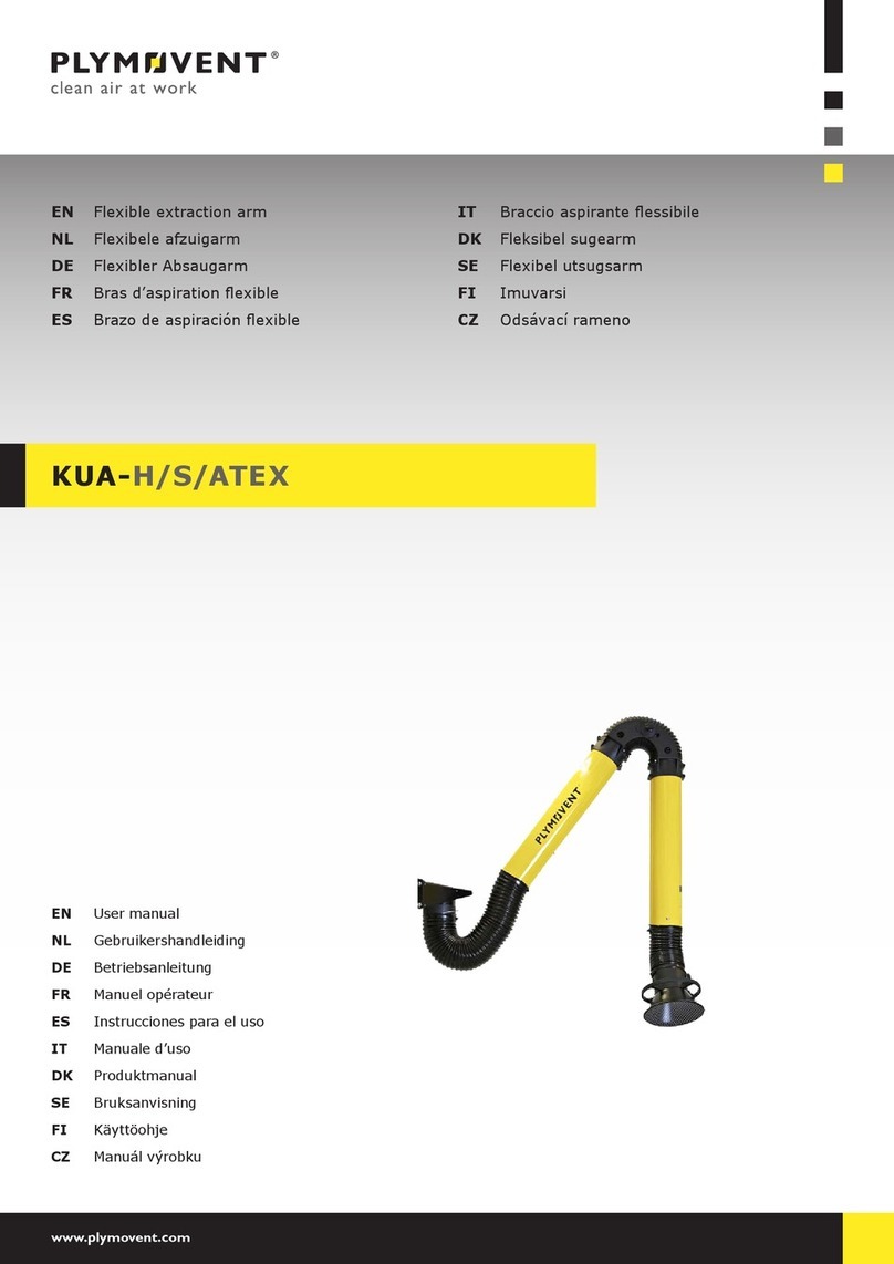
Plymovent MOBILEPRO User manual

www.plymovent.com
EN Mobile welding fume extractor
NL Mobiele lasrookafzuiger
DE Mobiler Schweißrauchabsauger
FR Epurateur mobile des fumées de soudure
ES Aspirador móvil de humos de soldadura
IT Estrattore mobile per fumi di saldatura
PL
EN Installation and user manual
NL Installatie- en gebruikershandleiding
DE Installations- und Betriebsanleitung
FR Manuel d’installation et d’utilisation
ES Manual de instalación y de uso
IT Manuale di installazione e d’uso
PL
MOBILEPRO | MOBILEPRO/PTFE

0000104750/210616/B MobilePro | MobilePro/PTFE 1
EN – OrigiNal iNstructiON
All rights reserved. The information given in this document has been collected for the general convenience of our clients. It has been based on general data pertaining to construction material
properties and working methods known to us at the time of issue of the document and is therefore subject at any time to change or amendment and the right to change or amend is hereby expressly
reserved. The instructions in this publication only serve as a guideline for installation, use, maintenance and repair of the product mentioned on the cover page of this document. This publication is to
be used for the standard model of the product of the type given on the cover page. Thus the manufacturer cannot be held responsible for any damage resulting from the application of this publication
to the version actually delivered to you. This publication has been written with great care. However, the manufacturer cannot be held responsible, either for any errors occurring in this publication or
for their consequences.
To improve comprehension for people whose rst language is not English, we have written parts of this manual in Simplied Technical English (STE). STE is a controlled language
originally developed for aerospace industry maintenance manuals. It offers a carefully limited and standardized subset of English, along with specic writing rules.
Nl – VErtaliNg VaN DE OOrsprONkElijkE gEbruiksaaNwijziNg
Alle rechten voorbehouden. De in deze handleiding verstrekte informatie is gebaseerd op algemene gegevens aangaande de ons ten tijde van verschijnen bekende constructies, materiaaleigenschappen
en werkmethoden, zodat wijzingen worden voorbehouden. Om deze reden dienen de gegeven instructies slechts als richtlijn voor het installeren, gebruiken, onderhouden en repareren van het op de
voorzijde van dit document vermelde product. Deze handleiding is geldig voor het product in de standaard uitvoering. De fabrikant kan derhalve niet aansprakelijk worden gesteld voor eventuele schade
voortvloeiend uit de van de standaard uitvoering afwijkende specicaties van het aan u geleverde product. Deze handleiding is met alle mogelijke zorg samengesteld, maar de fabrikant kan geen
verantwoording op zich nemen voor eventuele fouten in deze handleiding of voor de gevolgen daarvan.
DE – ÜbErsEtzuNg DEr OrigiNalbEtriEbsaNlEituNg
Alle Rechte vorbehalten. Die in dieser Anleitung enthaltenen Informationen basieren auf allgemeinen Daten bezüglich der Konstruktion, der Materialeigenschaften und der Arbeitsmethoden, die uns zur
Zeit der Veröffentlichung bekannt waren; Änderungen werden somit vorbehalten. Aus diesem Grunde dienen die gegebenen Vorschriften nur als Leitfaden für das Installieren, Benutzen, Warten und
Reparieren des auf der Vorderseite dieser Anleitung angegebenen Produktes. Diese Ausgabe gilt für die Standardausführung des Produktes. Der Hersteller haftet daher nicht für eventuelle Schäden,
die sich aus der Anwendung dieser Ausgabe auf Ihr von der Standardausführung abweichendes Produkt ergeben. Diese Ausgabe wurde mit größter Sorgfalt zusammengestellt. Der Hersteller haftet
jedoch nicht für eventuelle Fehler in dieser Ausgabe oder für daraus resultierende Folgen.
Fr – traDuctiON DE la NOticE OrigiNalE
Tous droits réservés. Le présent manuel a été mis au point à partir de données relatives à la construction, aux caractéristiques des matériaux et aux méthodes de production dont nous étions au
courant à la parution du manuel. Le manuel est donc sujet à modication à tout moment et nous nous réservons explicitement le droit à une telle modication. Pour la même raison, ce manuel servira
simplement de guide à l’installation, l’emploi, l’entretien et la réparation du produit gurant en première page de couverture de ce document. Le présent manuel s’applique au modèle standard du
produit. Par conséquent, le fabricant n’est pas responsable pour les dommages éventuels découlant de l’application de ce document aux modèles non standard des produits livrés. Nous avons apporté
tous nos soins à la rédaction de ce manuel, mais le fabricant ne peut pas accepter la responsabilité pour les erreurs éventuelles ni pour les dommages qui en découlent.
Es – traDuccióN DEl MaNual OrigiNal
Todos los derechos reservados. La información proporcionada en este documento se ha recopilado para el interés general de nuestros clientes. Se ha basado en datos generales referentes a las
propiedades del material de construcción y los métodos de trabajo que conocemos en el momento de la publicación del documento y, por consiguiente, están sujetos en cualquier momento a cambios o
correcciones, por lo que por la presente nos reservamos el derecho a hacer cambios o correcciones. Las instrucciones de esta publicación sólo sirven como pauta para la instalación, uso,
mantenimiento y reparación del producto mencionado en la portada de este documento. Esta publicación se deberá usar para el modelo estándar del producto de la clase indicada en la portada. Por
tanto, no se podrá responsabilizar al fabricante de ningún daño derivado de la utilización de esta publicación en la versión que se le ha entregado a Ud. Esta publicación se ha escrito con sumo cuidado.
Sin embargo, no se podrá responsabilizar al fabricante ni por los errores que haya en esta publicación ni por sus consecuencias.
it – traDuziONE DEllE istruziONi OrigiNali
Tutti i diritti riservati. Le informazioni fornite in questo documento sono state raccolte per il vantaggio generale dei nostri clienti. Sono state basate sui dati generali riguardanti le proprietà dei
materiali di costruzione e i metodi operativi a noi noti al momento dell’emissione del documento e sono quindi soggette in qualsiasi momento a cambiamenti o revisioni e il diritto di cambiare o rivedere
è espressamente riservato con il presente. Le istruzioni in questa pubblicazione servono solo come linee guida per l’installazione, l’uso, il mantenimento e la riparazione del prodotto menzionato nella
pagina di copertina di questo documento. Questa pubblicazione deve essere utilizzata per il modello standard del prodotto del tipo indicato nella pagina di copertina. In questo modo il fabbricante non
può essere ritenuto responsabile per qualsiasi guasto risultante dall’applicazione di questa pubblicazione alla versione effettivamente consegnata a voi. Questa pubblicazione è stata scritta con grande
cura. Tuttavia, il fabbricante non può essere ritenuto responsabile, né per qualsiasi errore contenuto in questa pubblicazione né per le sue conseguenze.
pl – Tłumaczenie oryginalnej insTukcji
Wszelkie prawa zastrzeżone. Informacje zawarte w niniejszym dokumencie zostały zebrane dla ogólnej wygody naszych klientów. Został on oparty na ogólnych danych dotyczących właściwości
użytych materiałów konstrukcyjnych i metod pracy znanych nam w momencie wystawienia dokumentu i podlega zatem w każdej chwili zmianie. Prawo do zmiany lub uzupełnienia zostaje niniejszym
wyraźnie zastrzeżone. Instrukcje zawarte w niniejszej publikacji służą jedynie jako wytyczne dla instalacji, eksploatacji, konserwacji i napraw produktu wymienionego na stronie tytułowej niniejszego
dokumentu. Publikacja ta ma być stosowany do standardowego modelu produktu, typu podanego na pierwszej stronie. W ten sposób producent nie może ponosić odpowiedzialności za szkody wynikłe
ze stosowania niniejszej publikacji do wersji faktycznie dostarczonej do użytkownika. Niniejsza publikacja została napisana z wielką starannością. Jednak producent nie może być pociągnięty do
odpowiedzialności za jakiekolwiek błędy zawarte w niniejszej publikacji lub ich konsekwencje.

0000104750/210616/B MobilePro | MobilePro/PTFE 2
ENGLISH Page NEDERLANDS Pag. DEUTSCH Seite
Preface 3 Voorwoord 12 Vorwort 21
1. Introduction 3 1. Inleiding 12 1. Einleitung 21
2. Product description 4 2. Productbeschrijving 13 2. Produktbeschreibung 22
3. Safety 5 3. Veiligheid 14 3. Sicherheitsvorschriften 23
4. Installation 6 4. Installatie 15 4. Installation 24
5. Use 7 5. Gebruik 17 5. Betrieb 26
6. Maintenance 8 6. Onderhoud 18 6. Wartung 27
7. Troubleshooting 10 7. Verhelpen van storingen 19 7. Fehlerbehebung 28
8. Spare parts 10 8. Reserveonderdelen 20 8. Ersatzteile 29
9. Electrical diagram 11 9. Elektrisch schema 20 9. Schaltplan 29
10. Disposal 11 10. Afdanken 20 10. Entsorgung 29
CE declaration 11 CE-verklaring 20 Konformitätserklärung 29
FRANÇAIS Page ESPAÑOL Pág. ITALIANO Pag.
Avant-propos 30 Preámbulo 40 Prefazione 50
1. Introduction 30 1. Introducción 40 1. Introduzione 50
2. Description de produit 31 2. Descripción del producto 41 2. Descrizione del prodotto 51
3. Instructions de sécurité 32 3. Normativas de seguridad 42 3. Istruzioni per la sicurezza 52
4. Installation 33 4. Instalación 43 4. Installazione 53
5. Utilisation 35 5. Uso 45 5. Uso 55
6. Entretien 36 6. Mantenimiento 46 6. Mantenimento 55
7. Réparation des pannes 37 7. Subsanación de fallos 47 7. Riparazione dei guasti 57
8. Pièces détachées 38 8. Piezas de recambio 48 8. Pezzi de ricambi 58
9. Schéma électrique 39 9. Esquema eléctrico 48 9. Diagramma elettrico 58
10. Mettre au rebut 39 10. Desechar 48 10. Scartare 58
Déclaration de Conformité 39 Declaración CE 49 Dichiarazione CE 58
POLSKI Strona
Wprowadzenie 59
59
2. Opis produktu 60
61
4. Instalacja 62
64
65
66
67
9. Schemat elektryczny 68
10. Utylizacja 68
Deklaracja CE 68
TABLE OF CONTENTS

0000104750/210616/B MobilePro | MobilePro/PTFE EN - 3
PREFACE
Using this manual
This manual is intended to be used as a work of reference for
professional, well trained and authorised users to be able to
safely install, use, maintain and repair the product mentioned
on the cover of this document.
Pictograms and symbols
The following pictograms and symbols are used in this manual:
TIP
Suggestions and recommendations to simplify
carrying out tasks and actions.
ATTENTION
A remark with additional information for the user. A
remark brings possible problems to the user’s
attention.
CAUTION!
Procedures, if not carried out with the necessary
caution, could damage the product, the workshop or
the environment.
WARNING!
Procedures which, if not carried out with the
necessary caution, may damage the product or
cause serious personal injury.
CAUTION!
Denotes risk of electric shock.
WARNING!
WARNING!
Explosion hazard! Important warning to prevent
explosions.
Personal protective equipment (PPE)
Instruction to use respiratory protection when you
do service, maintenance and repair jobs, as well as
during functional testing. We recommend to use a
half-face respirator according to DIN EN 141/143,
protection class P3.
Personal protective equipment (PPE)
Instruction to use protective gloves when you do
service, maintenance and repair jobs.
Text indicators
Listings indicated by “-” (hyphen) concern enumerations.
perform.
Service and technical support
repair jobs which are not dealt with in this manual, please
contact the supplier of the product. He will always be willing to
hand:
- product name
- serial number
Product indications
to the MobilePro as well as the MobilePro/PTFE.
1 INTRODUCTION
1.1
following data:
- product name
- serial number
- supply voltage and frequency
- power consumption
1.2 General description
tray at the bottom of the unit. Thanks to the four transport
wheels (two of which are swivel casters with brake), the
MobilePro is suitable to be used in relatively small facilities or
handlebar allows to place tools on the unit and prevents them
from falling off.
1.3 Product combinations
To operate the unit, selection of one of the following products
is required:
Ball-bearing extraction arm (360° rotatable):
- KUA-2/S | 2 m (6.5 ft)
- KUA-3/S | 3 m (10 ft)
- KUA-4/S | 4 m (13 ft)
Hose tube extraction arm (360° rotatable):
- EA-3/S | 3 m (10 ft)
- EA-4/S | 4 m (13 ft)
1.3.1 Options and accessories
The following products can be obtained as an option and/or
accessory:
-
(instead of CART-O)
- HL-20/24-160 | Halogen working light with switch box (arm
359° rotatable)
-
1.4
Physical dimensions and properties
Material (housing) electro-zinc coated steel
Weight 169 kg (373 lbs.)
Capacity of dust tray 10 litres (2.6 gallon)
Filter cartridge
MobilePro MobilePro/PTFE
Type CART-O CART-O/PTFE
Filter material 100% BiCo
polyester
100% BiCo
polyester with PTFE
membrane
Filter surface area 20 m² (215 ft²) 10 m² (108 ft²)
Dust class (according to
DIN EN 60335-2-69)
M M
Filter class (according to
ASHRAE 52.2)
MERV 11 MERV 16
Washable (e.g. by using
Plymovent EFC detergent)
yes no
Compressed air system
Required compressed air
quality
dry and oil-free according to ISO 8573-3
class 6

0000104750/210616/B MobilePro | MobilePro/PTFE EN - 4
Inlet pressure 5-10 bar (75-150 PSI)
Required pressure 5 bar (75 PSI) (by integrated pressure
regulator)
Compressed air
connection
G 3/8” (female)
Compressed air
consumption
35 Nl (1.2 ft³) per pulse
Volume of compressed air
tank
10 litres (2.6 gallon)
cleaning system (online
only)
- pressure controlled (threshold value:
1000 Pa)
- manually by push button
cycle
60 seconds (6 pulses)
Fan
Fan type radial
Extraction capacity
extraction arm)
Fan speed:
- 50 Hz
- 60 Hz
- 2900 rpm
- 3390 rpm
Noise level 72 dB(A) according to ISO 3746
Electrical data
Power consumption 1,1 kW (1.5 HP)
Available connection
voltages
- 115V/1ph/50Hz
- 115V/1ph/60Hz
- 230V/1ph/50Hz
- 400V/3ph/50Hz+N
Motor design IEC
- single phase motor
- three-phase motor
- n.a.
- IE3 / premium
Mains cord:
- type
- length
- SJOOW 3xAWG14
- 4,5 m (14.8 ft)
Plug:
- 115V/1ph/50Hz
- 115V/1ph/60Hz
- 230V/1ph/50Hz
- 400V/3ph/50Hz+N
Type:
- none
- NEMA 5-15P
- none
- none
IFA W3 pending
Refer to the available product data sheet for
1.5 Dimensions
Refer to Fig. I on page 69.
1.6 Working range
Refer to Fig. II on page 69.
1.7 Ambient conditions
Process temperature:
- min.
- nom.
- max.
5°C (41°F)
20°C (68°F)
70°C (158°F)
Max. relative humidity 90%
Suitable for outdoor use no
1.8
You cannot hold the manufacturer liable for any transportation
damage after delivery of the product. Handle the machine and
the accompanying extraction arm with care. Completely
dismount the extraction arm before transport. Dismount the
arm by executing the mounting procedure in reverse order.
Subsequently the machine and the arm can be transported on
a pallet in the original packing.
To prevent damage, make sure that the machine and the arm
cannot shift on the pallet.
2 PRODUCT DESCRIPTION
2.1 Components
The unit consists of the following main components and
elements:
Fig. 2.1
A
B
C dust tray
D handlebar
E control panel
F extraction fan
G outlet grid (2x)
H
Fig. 2.1
C
D
E
F
G H
B
A
Main components and elements
2.2 Operation
The MobilePro works in accordance with the recirculation
principle. Welding fume is extracted through the hood of the
connected extraction arm by the built-in fan. The polluted air
1
cartridge. The welding fume particles are collected at the
workshop through the outlet grids on the sides of the unit.
2.2.1 Filter cleaning system
consequently the extraction capacity reduces -, a pressure
cleaning system can be activated manually as well. The dust
and dirt particles fall into the dust tray.
The cleaning system only operates when the fan is running, to
prevent dust particles to escape through the hood of the
extraction arm.
1.

0000104750/210616/B MobilePro | MobilePro/PTFE EN - 5
The unit enters into the ALARM stage2when the differential
1000 Pa.
3 SAFETY
General
The manufacturer does not accept any liability for damage to
the product or personal injury caused by ignoring of the safety
instructions in this manual, or by negligence during
installation, use, maintenance, and repair of the product
mentioned on the cover of this document and any
corresponding accessories.
additional safety instructions. Immediately contact your
supplier if you detect a potential danger when using the
product.
regulations.
User manual
- Everyone working on or with the product, must be familiar
with the contents of this manual and must strictly observe
the instructions therein. The management should instruct the
personnel in accordance with the manual and observe all
instructions and directions given.
- Do not change the order of the steps to perform.
- Keep the manual with the product.
Users
- The use of this product is exclusively reserved to authorised,
personnel in training can only use the product under
supervision and responsibility of skilled engineers.
- Stay alert and keep your attention to your work. Do not use
alcohol or medicine.
- The product is not to be used by children or persons with
reduced physical, sensory or mental capabilities, or lack of
experience and knowledge, unless they have been given
supervision or instruction.
- Children must be supervised not to play with the product.
Intended use3
The product has been designed exclusively for extracting and
most common welding processes. Using the product for other
purposes is considered contrary to its intended use. The
manufacturer accepts no liability for any damage or injury
resulting from such use. The product has been built in
accordance with state-of-the-art standards and recognised
safety regulations. Only use this product when in technically
perfect condition in accordance with its intended use and the
instructions explained in the user manual.
2. During the ALARM stage the fan continues to run.
3. “Intended use” as explained in EN-ISO 12100-1 is the use for which the
directions in the sales brochure. In case of doubt it is the use which can be
deduced from the construction, the model and the function of the technical
product which is considered normal use. Operating the machine within the
limits of its intended use also involves observing the instructions in the user
manual.
Product combinations
If the product is used in combination with other products or
machines, the safety instructions in the documentation of
these products also apply.
Installation
- The installation of this product is exclusively reserved to
- The electric connection must be executed in accordance with
the local codes and requirements. Ensure compliance with
the EMC regulatory arrangements.
- During installation, always use Personal Protective
Equipment (PPE) to avoid injury. This also applies to persons
who enter the work area during installation.
- Make sure that the workspace is well illuminated.
- Stay alert and keep your attention to your work. Do not
drugs, alcohol or medicine.
Use
WARNING!
Fire hazard! Do not use the product for:
- polishing applications in combination with grinding,
welding or any other application that generate
sparks.
sparks.)
- arc-air gouging
-
burning particles or solids or liquids
-
(such as hydrochloric acid) or sharp particles
-
released when welding surfaces treated with
primer
- sucking cigarettes, cigars, oiled tissues, and other
burning particles, objects, and acids
WARNING!
Explosion hazard! Do not use the product for
explosion-hazardous applications, e.g.:
- aluminium laser cutting
- grinding aluminium and magnesium
WARNING!
Do not use the product for:
- extraction of hot gases (more than 70°C/158°F
continuously)
-
- Inspect the product and check it for damage. Verify the
functioning of the safety features.
- Do not put the product in front of entrances and exits which
must be used for emergency services.
- During use, always use Personal Protective Equipment (PPE)
to avoid injury. This also applies for persons who enter the
work area.
- Check the working environment. Do not allow unauthorised
persons to enter the working environment.
- Protect the product against water and humidity.
-
- Make sure that the workshop, in the vicinity of the product,
- The welding current return circuit between the workpiece
and the welding machine has a low resistance. Thus avoid
connection between the workpiece and the MobilePro, so that
the welding machine via the protective earth conductor of
the MobilePro.
0000104750/210616/B MobilePro | MobilePro/PTFE EN - 6
Service, maintenance and repairs
- Obey the maintenance intervals given in this manual.
Overdue maintenance can lead to high costs for repair and
revisions and can render the guarantee null and void.
- Always use Personal Protective Equipment (PPE) to avoid
injury. This also applies for persons who enter the work area.
-
- Use tools, materials, lubricants and service techniques which
have been approved by the manufacturer. Never use worn
tools and do not leave any tools in or on the product.
- Clean the area afterwards.
ATTENTION
Service, maintenance and repairs must be
performed in accordance with directive TRGS 560
persons (skilled) using appropriate work practices.
ATTENTION
Before you carry out service, maintenance and/or
repair jobs:
- fully disconnect the unit from the mains
- disconnect the compressed air supply
Personal protective equipment (PPE)
Wear respiratory protection and protective
gloves during service, maintenance and
repairs.
WARNING
The industrial vacuum cleaner that you use during
service and maintenance must meet dust class H
according to EN 60335-2-69 or HEPA class
4 INSTALLATION
4.1 Tools and requirements
You need the following tools and requirements to install the
unit:
- basic tools
4.1.1 To be sourced locally
For connection to the local mains (50 Hz types only):
- a suitable plug
-
- adhesive cable tie mounts and cable ties or equivalent
4.2 Unpacking
Make sure that the product is complete. The package contains:
-
- hexagon bolt M6x25 (8) + washer (8) for connection of the
extraction arm
- cable gland (2) for connection of the optional working light
HL-20/24-160
Refer to Fig. III on page 69 for instructions to
take the unit from the pallet.
ATTENTION!
Do not use a fork-lift truck to lift the unit. It will
damage the dust tray.
4.3 Extraction arm
To operate the MobilePro you must install one of the following
extraction arms:
- KUA-2/S / KUA-3/S / KUA-4/S (ball bearing extraction arm)
- EA-3/S / EA-4/S (hose tube extraction arm)
To install the extraction arm, proceed as follows.
Fig. 4.1
8 bolts M6x25 + washers.
Move the hose clamp (D) and the rubber collar (E) over the
hinge rod (B).
Put the swivel ring (F) over the hinge rod (B)4.
Put the washer (G) over the hinge rod.
ATTENTION!
Make sure to install the washer between the
it with the locking pin (C). Tighten it with a hex key.
Put the hose (A) over the swivel ring (F).
Tighten the hose with the hose clamp (D).
Put the rubber collar (E) over the connection between the
airtight.
Fig. 4.1
H
G
E
F
C
A
A
D
F
E
H
D
B
Mounting of the extraction arm
To assemble and adjust the extraction arm itself,
refer to the corresponding manual.
4.3.1 Option: working light HL-20/24-160
Fig. 4.2
Install the working light in the hood of the extraction arm
in accordance with the instruction sheet.
Attach the cable (A) to the tubes of the arm and to the
unit, e.g. with adhesive cable tie mounts and cable ties.
Make sure that the cable is long enough:
-
and
- to rotate the extraction arm (max. 359°)
4. The dashed line indicates the end position.

0000104750/210616/B MobilePro | MobilePro/PTFE EN - 7
Fig. 4.2
A
Mounting of the working light cable
Fig. 4.3
Loosen the bolt M10 (A) at the bottom the unit. Continue
to turn the bolt until it gets fully loose5.
Fig. 4.3
±25 mm
(1 in.)
A
A
Bolt to unlock the front panel
Fig. 4.4
Push the front cover (A) down and remove it.
Fig. 4.4
±25 mm
(1 in.)
A
A
Disassembly of the front cover
Fig. 4.5
Remove the cover of the control panel (ref. Fig. 4.6B).
Remove the cover caps at position B and C.
Put a cable gland in both holes.
Put the cable (A) through the cable glands.
Tighten the cable glands.
Connect the cable to the terminal block inside the control
panel in accordance with the separately supplied electrical
diagram.
5. The nut is locked to the front panel, so you cannot entirely remove it.
Install the front cover of the unit (instructions of Fig. 4.3
and Fig. 4.4 in reverse order).
Install the cover of the control panel.
Fig. 4.5
A
B
C
Connection of the working light cable
4.4 Compressed air connection
ATTENTION
The compressed air must be dry and oil-free
according to ISO 8573-3 class 6.
Fig. 4.6
Connect the unit to the compressed air supply.
Fig. 4.6
A
B
Compressed air connection
4.5 Electric connection
Make sure that the unit is suitable for connection to the
local mains.
Put the plug in the socket.
5 USE
WARNING!
Fire hazard! Do not use the product for polishing
applications in combination with grinding, welding or
any other application that generate sparks.
Refer to chapter 3 / Use.
5.1 Control panel
The control panel contains the following controls and indicator
lights:

0000104750/210616/B MobilePro | MobilePro/PTFE EN - 8
Fig. 5.1
A ALARM | red light to indicate that the pressure drop exceeds
the threshold value6
B MANUAL CLEANING | black push button7
cleaning system manually
C START / STOP | push button with green LED to start and stop
the fan
Fig. 5.1
Dimension: 318 x 198 mm
Colour: background Pantone Black C 20% / Printing black
MobilePro
MANUAL CLEANING
START / STOP
ALARM
0000104690/0
HANDMATIGE FILTERREINIGING
MANUELLE FILTERREINIGUNG
DÉCOLMATAGE MANUEL DU FILTRE
LIMPIEZA MANUAL DEL FILTRO
AAN / UIT
EIN / AUS
MARCHE / ARRÊT
ARRANQUE / PARO
ALARME
ALARMA
A
B
C
Control panel
5.2 Use
Since it concerns a mobile unit, you can use it at any desirable
place. For optimal results you must place the unit as close as
possible to the source of pollution.
If possible:
Connect the unit to the external compressed air supply.
Refer to section 5.3 (“preferred way”).
Position the hood of the connected extraction arm at
400-800 mm (16-32 in.) from the source of pollution. Refer
to Fig. IV on page 70 for the correct position.
Push the START/STOP button (ref. Fig. 5.1C) to start the fan.
Start welding.
When the welding position changes, move the hood to the
correct position in relation to the weld.
WARNING
To keep the welding fume away from the breathing
zone of the welder, make sure that all fume is
extracted through the hood.
Push the START/STOP button approx. 20 seconds after you
During use, do a regular check on the status of the ALARM
indicator light (ref. Fig. 5.1A). When the ALARM light is on, it
means that the pressure drop exceeds the threshold value.
This can have two causes:
Proceed with section 5.3.1.
Proceed with section 6.3.
To suppress the ALARM light temporarily: push the
START/STOP button two times (off and on). The
ALARM light comes on again after 10 minutes, unless
you have solved the problem.
6. Delay time: 10 minutes
7. To activate: push and hold 5 seconds
WARNING
If you do not take the necessary action to solve the
drops.
5.3 Filter cleaning system
One cleaning cycle takes approx. 60 seconds and consists of
six compressed air pulses.
We recommend to keep the compressed air supply connected
during use. In this situation, a pressure switch activates the
reaches the threshold value. This guarantees the optimum
performance of the unit and prevents the unit to go into
ALARM.
Alternative
If it is not possible to have compressed air available during
manually.
1. Activate MANUAL CLEANING on a regular basis8before the
unit goes into ALARM
cartridge and optimizes the performance of the unit.
2. Activate MANUAL CLEANING as soon as the unit goes into
ALARM9.
5.3.1 Manual lter cleaning
follows.
Connect the unit to the compressed air supply.
Make sure that the fan is running: the green LED (ref. Fig.
5.1C) is on.
Push and hold the MANUAL CLEANING button (ref. Fig. 5.1B)
for 5 seconds to activate the cleaning system.
Push the START/STOP button (ref. Fig. 5.1C). two times (off
and on) to reset the ALARM light.
6 MAINTENANCE
6.1 Periodic maintenance
The product has been designed to function without problems
for a long time with a minimum of maintenance. In order to
guarantee this some simple, regular maintenance and cleaning
activities are required which are described in this chapter. If
you observe the necessary caution and carry out the
maintenance at regular intervals, any problems occurring will
be detected and corrected before they lead to a total
breakdown.
WARNING!
The indicated maintenance intervals can vary depending on
recommended to thoroughly inspect the complete product
once every year beside the indicated periodic maintenance. For
this purpose contact your supplier.
8. The optimum frequency to activate the cleaning system manually depends on
the intensity of use and will be a matter of experience.
9. During the ALARM stage the fan continues to run.

0000104750/210616/B MobilePro | MobilePro/PTFE EN - 9
Component Action Frequency: every X
months
X=
X=3 X=6 X =12
Dust tray
section 6.2.
X *)
Housing Clean the outside
with a non-aggressive
detergent.
X
Clean the inside with
an industrial vacuum
cleaner and remove
compartment.
X
Check sealing
material. Replace if
necessary.
X
Filter
cartridge
Check for damage,
clogging and
saturation. Replace if
necessary.
X
Extraction fan Check for encrusted
particles. Clean if
necessary.
X
Pressure
regulator
Make sure that the
pressure setting is
correct (5 bar).
X
Mains cord Check for damage.
Repair or replace if
necessary.
X **)
*) During use, you must check the level of contents in the dust tray
regularly. The emptying frequency depends on the intensity of use
and will be a matter of experience.
In the initial stage, do a check on the level of contents of the dust
tray 2 times per month.
**) Before every use
6.2 Emptying the dust tray
Location of the dust tray: in the dust tray holder at the bottom
of the unit. The dust tray holder is locked by a draw latch (ref.
Fig. 6.1A).
Personal protective equipment (PPE)
Wear respiratory protection and protective
gloves when you empty the dust tray.
ATTENTION
The industrial vacuum cleaner that you use to
empty the dust tray must meet dust class H
according to EN 60335-2-69 or HEPA class
WARNING
- Prevent excessive draughts.
- Do not empty the dust tray while the fan is
running.
To empty the dust tray, proceed as follows.
Fig. 6.1
Option: push and hold the MANUAL CLEANING button (ref.
Fig. 5.1B and section 5.3.1) for 5 seconds to activate an
additional cleaning cycle. This takes approx. 60 seconds.
If applicable: disconnect the compressed air supply.
De-energize the unit.
Unlock the dust tray. The dust tray holder (B) comes down.
Gradually take out the dust tray (C) and empty it with an
industrial vacuum cleaner at the same time.
Put the dust tray back in the holder and lock it.
Fig. 6.1 Emptying the dust tray
C
B
A
6.3 Filter replacement
Personal protective equipment (PPE)
Wear respiratory protection and protective
cartridge.
WARNING
Do not
running.
Option: push and hold the MANUAL CLEANING button (ref.
Fig. 5.1B and section 5.3.1) for 5 seconds to activate an
additional cleaning cycle. This takes approx. 60 seconds.
If applicable: disconnect the compressed air supply.
De-energize the unit.
Loosen the star knob (F) and disassemble the cover plate
(E), the nut (D) and the metal washer (C).
Seal the sack securely.
attach it with the disassembled parts. Make sure that you
tighten the nut (D) correctly and that you mount the cover
plate (E) in the right position10.
federal, state or local regulations.
Clean the environment of the unit.
Fig. 6.2
BA C D FE
Filter replacement
10. Sticker “UP” indicates the top of the cover plate.

0000104750/210616/B MobilePro | MobilePro/PTFE EN - 10
6.3.1 Filter washing
11.
Personal protective equipment (PPE)
Wear respiratory protection and protective
ATTENTION
-
-
Soak it in water with EFC detergent at max. 60°C (140°F).
Hose it clean.
Let it dry thoroughly.
ATTENTION
No steam cleaning.
7 TROUBLESHOOTING
If the unit does not function (correctly), consult the checklist
below to see if you can remedy the error yourself. Should this
not be possible, contact your supplier.
WARNING
Obey the safety regulations that are written in
chapter 3 when you carry out the activities below.
Symptom Problem Possible
cause
Solution
ALARM light
is on
cleaning
No compressed
air available or
air pressure too
low
Connect or repair
the compressed air
supply.
Subsequently:
- push the MANUAL
CLEANING button
(hold for 5
seconds)
- push the START/
STOP button two
times to reset the
ALARM light
cartridge
cartridge
The ALARM
light remains
on after
cleaning
- No reset Push the START/
STOP button 2
times (off and on)
Extraction
capacity
cartridge
cartridge
The fan does
not start
The unit does
not function
No mains
voltage
Connect the mains
voltage
The mains cord
is defective
Repair or replace
the mains cord
Loose contacts Repair the contacts
Motor defective Repair or replace
the motor
START/STOP
button (green)
is defective
Replace the green
button
Thermal relay is
activated
Reset the thermal
relay
11.
is clogged.
Symptom Problem Possible
cause
Solution
The fan does
not start
(cont.)
The unit does
not function
Thermal relay is
defective
Replace the thermal
relay
The fan
makes a
humming
sound, but
does not run
Extraction
capacity
no extraction
at all
Motor uses 2
phases instead
of 3 (3-phase
motor only)
Repair the phase
connection
Poor
extraction
capacity
The unit does
not function
properly
Inverted
direction of
rotation of the
motor (3-phase
motor only)
Change the
direction of rotation
cartridge
cartridge
Pollution of
the facility
Filter cartridge
ripped or
placed
incorrectly
cartridge or place it
correctly
cleaning
Loose
compressed air
connection
Repair the
compressed air
connection
No compressed
air available or
air pressure too
low
Connect or repair
the compressed air
supply
Membrane
valve defective
or worn
Replace the
membrane valve
Hissing sound
cleaning
Membrane
valve defective
or worn
Replace the
membrane valve
MANUAL
CLEANING
button does
not react.
No manual
activation of
cleaning
system
The button is
not held long
enough.
Push and hold the
button for 5
seconds.
MANUAL
CLEANING
button (black)
is defective.
Replace the black
button.
8 SPARE PARTS
The following spare parts are available for the product (refer to
exploded view Fig. V on page 71).
Article no. Description
General
0000101364 Wheel cover grey (2 pieces)
0000101409 Fuse 3.15A 5x20 mm UL
0000101413 Transformer 120-575V 24V 75VA
0000101751 CART-O / Filter cartridge12 [MobilePro only]
0000101752 CART-OA / Filter cartridge12 [MobilePro only]
0000102220 Pressure switch 800 Pa
0000102411 Drain valve ½ inch
0000102584
0000102598 Star knob M12
0000102762
0000104768 Indicator light red
0000104961 PC board MobilePro, incl. software
0000110155 CART-O/PTFE / Filter cartridge12 [MobilePro/PTFE only]
0040900010 Magnetic valve AC
0040900120 Push button black
0040900130 Push button green incl. LED
0805030010 Wheel Ø 250 mm black (excl. wheel cover)
0805040010 Swivel castor Ø 125 mm with brake

0000104750/210616/B MobilePro | MobilePro/PTFE EN - 11
Article no. Description
0000101440 Relay 100-C23KJ10
0000101444 Fuse class CC 0,5 A
0000103068 Fan wheel (60Hz)
0000104960
0040900220 Thermal relay 3,2-16 A
0000104069 Fan wheel (50Hz)
9 ELECTRICAL DIAGRAM
Refer to the separately supplied electrical diagram.
DISPOSAL
persons.
Personal protective equipment (PPE)
Wear respiratory protection and protective
gloves when you dismantle and dispose of
the unit.
Dismantling
To safely dismantle the unit, obey the safety instructions that
follow.
Before dismantling of the unit:
- disconnect it from the mains
- disconnect it from the compressed air
- clean the outside
During dismantling of the unit:
-
mobile ventilation unit
After dismantling of the unit:
- clean the dismantling area
Disposal
Dispose of the pollutants and dust, together with the used
federal, state or local regulations.
12. Filter cartridge, incl. face mask, disposable gloves and plastic sack with seal for
CE DECLARATION
We, Plymovent Manufacturing B.V., Koraalstraat 9, 1812 RK
Alkmaar, Netherlands, herewith declare, on our own
responsibility, that the products:
- MobilePro
- MobilePro/PTFE
which this declaration refers to, are in accordance with the
conditions of the following Directives:
- Machine Directive 2006/42 EC
- EMC 2004/108 EC
- LVD 2006/95 EC
- ErP Directive 2009/125 EC
Signature:
Name: M.S.J. Ligthart
Position: Product Manager
Date of issue: 1st June 2016

0000104750/210616/B MobilePro | MobilePro/PTFE NL - 12
VOORWOORD
Gebruik van deze handleiding
Deze handleiding is bedoeld als naslagwerk waarmee
professionele, geschoolde en daartoe bevoegde gebruikers het
aan de voorzijde van dit document vermelde product op veilige
wijze kunnen installeren, gebruiken, onderhouden en
repareren.
Pictogrammen en symbolen
In deze handleiding worden de volgende pictogrammen en
symbolen gebruikt:
TIP
Suggesties en adviezen om de betreffende taken of
handelingen gemakkelijker te kunnen uitvoeren.
LET OP!
Een opmerking met aanvullende informatie voor de
gebruiker. Een opmerking maakt de gebruiker attent
op mogelijke problemen.
VOORZICHTIG!
Procedures die -wanneer ze niet met de nodige
voorzichtigheid worden uitgevoerd- schade aan het
product, de omgeving of het milieu tot gevolg
kunnen hebben.
WAARSCHUWING!
Procedures die -wanneer ze niet met de nodige
voorzichtigheid worden uitgevoerd- ernstige schade
aan het product of lichamelijk letsel tot gevolg
kunnen hebben.
VOORZICHTIG!
Gevaar voor elektrische spanning.
WAARSCHUWING!
Brandgevaar! Belangrijke waarschuwing ter
voorkoming van brand.
WAARSCHUWING!
Explosiegevaar! Belangrijke waarschuwing ter
voorkoming van explosies.
Persoonlijke beschermingsmiddelen (PBM)
Instructie voor het gebruik van adembescherming
bij het uitvoeren van service-, onderhouds- en
reparatiewerkzaamheden. Dit geldt tevens tijdens
het uitvoeren van een functionele test. Wij
adviseren een halfgelaatsmasker volgens DIN EN
141/143, beschermingklasse P3.
Persoonlijke beschermingsmiddelen (PBM)
Instructie voor het gebruik van beschermende
handschoenen bij het uitvoeren van service-,
onderhouds- en reparatiewerkzaamheden.
Tekstaanduidingen
Tekst aangegeven met een “-” (koppelteken) betreft een
opsomming.
verrichten stappen.
Service en technische ondersteuning
onderhouds- of reparatiewerkzaamheden die buiten het bestek
van deze handleiding vallen, gelieve contact op te nemen met
de leverancier van het product. Deze is altijd bereid u te
helpen. Zorg ervoor dat u de volgende gegevens bij de hand
heeft:
- productnaam
- serienummer
Productaanduidingen
van toepassing op zowel de MobilePro als de MobilePro/PTFE.
1 INLEIDING
1.1
- productnaam
- serienummer
- aansluitspanning en frequentie
- vermogen
1.2 Algemene beschrijving
van persluchtstoten. De stof wordt opgevangen in de
opvangbak aan de onderzijde van de unit. Dankzij de vier
transportwielen (waarvan twee zwenkwielen met rem), is de
MobilePro geschikt voor gebruik in relatief kleine ruimtes of in
de buurt van vervuilingsbronnen zonder vaste locatie. De
veelzijdige handgreep maakt het mogelijk om gereedschappen
op de unit te plaatsen zonder dat ze ervan af vallen.
1.3 Productcombinaties
De unit moet met een van de volgende producten worden
gecompleteerd:
Kogelgelagerde afzuigarm (360° draaibaar):
- KUA-2/S | 2 m
- KUA-3/S | 3 m
- KUA-4/S | 4 m
Flexibele afzuigarm met slang (360° draaibaar):
- EA-3/S | 3 m
- EA-4/S | 4 m
1.3.1 Opties en accessoires
De volgende producten zijn als optie en/of accessoire
verkrijgbaar:
-
(instead of CART-O)
- HL-20/24-160 | werklamp met bedieningselement (arm 359°
draaibaar)
-
1.4
Materiaal (behuizing) elektrolytisch verzinkt staal
Gewicht 169 kg
Capaciteit van de
stofopvangbak
10 liter
Filterpatroon
MobilePro MobilePro/PTFE
Type CART-O CART-O/PTFE
Filtermateriaal 100% BiCo
polyester
100% BiCo
polyester met PTFE
membraan
Filteroppervlakte 20 m² 10 m²
Stofklasse (volgens DIN
EN 60335-2-69)
MM
Filterklasse (volgens
ASHRAE 52.2)
MERV 11 MERV 16

0000104750/210616/B MobilePro | MobilePro/PTFE NL - 13
Wasbaar (bv. met het
reinigingsmiddel
Plymovent EFC)
ja nee
Persluchtsysteem
Vereiste persluchtkwaliteit vrij van olie en vocht volgens ISO 8573-3
klasse 6
Ingangsdruk 5-10 bar
Benodigde druk 5 bar (door geïntegreerd
drukregelventiel)
Persluchtaansluiting G 3/8” (vrouwelijk)
Persluchtverbruik 35 Nl per puls
Volume van de
persluchttank
10 liter
Activering van het
reiniginsmechanisme
(alleen online)
- drukgestuurd (drempelwaarde: 1000
Pa)
- handmatig d.m.v. drukknop
reinigingscyclus (6
pulsen)
60 seconden (6 pulsen)
Ventilator
Type radiaal
Afzuigcapaciteit
Ventilatorsnelheid:
- 50 Hz
- 60 Hz
- 2900 rpm
- 3390 rpm
Geluidsniveau 72 dB(A) volgens ISO 3746
Elektrische gegevens
Opgenomen vermogen 1,1 kW
Beschikbare
aansluitspanningen
- 115V/1ph/50Hz
- 115V/1ph/60Hz
- 230V/1ph/50Hz
- 400V/3ph/50Hz+N
Bouwvorm motor IEC
- eenfasemotor
- driefasenmotor
- n.v.t.
- IE3 / premium
Voedingskabel:
- type
- lengte
- SJOOW 3xAWG14
- 4,5 m (14.8 ft)
Netstekker:
- 115V/1ph/50Hz
- 115V/1ph/60Hz
- 230V/1ph/50Hz
- 400V/3ph/50Hz+N
Type:
- geen
- NEMA 5-15P
- geen
- geen
IFA W3 in behandeling
Zie het beschikbare productinformatieblad voor
1.5
Zie Fig. I op pagina 69.
1.6 Werkbereik
Zie Fig. II op pagina 69.
1.7 Omgevingscondities
Procestemperatuur:
- min.
- nom.
- max.
5°C
20°C
70°C
Max. relatieve vochtigheid 90%
Geschikt voor buitengebruik nee
1.8 Transport van de unit
De fabrikant kan op geen enkele wijze verantwoordelijk
voorzichtig met de machine en de bijbehorende afzuigarm om.
Voordat eventueel transport plaatsvindt, moet de afzuigarm
volledig losgekoppeld worden. Koppel de afzuigarm los door de
montageprocedure in omgekeerde volgorde uit te voeren.
Hierna kunnen de machine en de afzuigarm in de originele
verpakking op een pallet vervoerd worden.
Let erop dat de machine en de afzuigarm niet van de pallet
kunnen schuiven ter voorkoming van beschadigingen.
2 PRODUCTBESCHRIJVING
2.1 Componenten
De unit bestaat uit de volgende hoofdcomponenten en
-elementen:
Fig. 2.1
A
B
C stofopvangbak
D handgreep
E bedieningspaneel
F afzuigventilator
G uitblaasrooster (2x)
H
Fig. 2.1
C
D
E
F
G H
B
A
Hoofdcomponenten en -elementen
2.2 Werking
De MobilePro werkt op basis van het recirculatieprincipe. De
ingebouwde ventilator zuigt de lasrook via de kap van de
aangesloten afzuigarm aan. De vervuilde lucht passeert de
1
opgevangen. De schone lucht wordt via de uitblaasroosters
aan de zijkanten van de unit weer in de ruimte teruggevoerd.
2.2.1 Filterreinigingssysteem
afzuigcapaciteit afneemt - activeert een drukschakelaar de
1.

0000104750/210616/B MobilePro | MobilePro/PTFE NL - 14
kunt u ook handmatig activeren. De stof- en vuildeeltjes
komen terecht in de stofopvangbak.
Om te voorkomen dat stof via de kap van de afzuigarm de
als de ventilator draait.
De unit gaat in ALARM2wanneer het drukverschil over het
3 VEILIGHEID
Algemeen
De fabrikant aanvaardt geen enkele aansprakelijkheid voor
schade of letsel veroorzaakt door het niet (strikt) naleven van
de veiligheidsvoorschriften en -instructies in deze handleiding,
dan wel door onachtzaamheid tijdens installatie, gebruik,
onderhoud en reparatie van het op de voorzijde van dit
document vermelde product en de eventuele bijbehorende
accessoires.
gebruikte accessoires kunnen aanvullende
veiligheidsinstructies nodig zijn. Neem s.v.p. direct contact op
met uw leverancier indien u bij het gebruik van het product
een potentieel gevaar hebt geconstateerd.
De gebruiker van het product is te allen tijde volledig
Gebruikershandleiding
- Een ieder die aan of met het product werkt, dient van de
inhoud van deze handleiding op de hoogte te zijn en de
instructies daarin nauwgezet op te volgen. De bedrijfsleiding
dient het personeel aan de hand van de handleiding te
onderrichten en alle voorschriften en aanwijzingen in acht te
nemen.
- Wijzig nooit de volgorde van de te verrichten handelingen.
- Bewaar de handleiding steeds in de nabijheid van het
product.
Gebruikers
- Gebruik van het product is uitsluitend voorbehouden aan
daartoe opgeleide en bevoegde gebruikers. Tijdelijke
werkkrachten en personen in opleiding mogen het product
uitsluitend onder toezicht en verantwoording van vaklui
gebruiken.
- Blijf voortdurend opletten en houd uw aandacht bij het werk.
Gebruik het product niet als u onder invloed bent van drugs,
alcohol of medicijnen.
- Het product mag niet worden gebruikt door kinderen of
personen met beperkte fysieke, zintuiglijke of mentale
vermogens, tenzij onder toezicht of instructie.
- Kinderen moeten onder toezicht staan om te voorkomen dat
ze met het product gaan spelen.
Gebruik volgens bestemming3
Het product is uitsluitend ontworpen voor het afzuigen en
voorkomende lasprocessen. Elk ander of verdergaand gebruik
geldt niet als conform de bestemming. Voor schade of letsel
dat hiervan het gevolg is, aanvaardt de fabrikant geen enkele
aansprakelijkheid. Het product is in overeenstemming met de
vigerende normen en richtlijnen. Gebruik het product
2. Tijdens de ALARM-fase blijft de ventilator draaien.
3. “Gebruik volgens bestemming” zoals vastgelegd in de EN-ISO 12100-1 is het
gebruik waarvoor het technisch product volgens de opgave van de fabrikant
-inclusief diens aanwijzingen in de verkoopbrochure- geschikt is. Bij twijfel is
dat het gebruik dat uit de constructie, uitvoering en functie van het product als
gebruikelijk naar voren komt. Tot het gebruik volgens bestemming behoort ook
het in acht nemen van de instructies in de gebruikershandleiding.
uitsluitend in technisch perfecte conditie, conform de
hierboven beschreven bestemming.
worden gewijzigd.
toegestaan.
Productcombinaties
Indien het product wordt gebruikt in combinatie met andere
producten of machines, zijn eveneens de in de documentatie
van deze producten opgenomen veiligheidsvoorschriften van
toepassing.
Installatie
- Installatie van het product is uitsluitend voorbehouden aan
daartoe opgeleide en bevoegde installateurs.
- Elektrische aansluiting moet geschieden in overeenstemming
met de ter plaatse geldende voorschriften. Zorg voor
naleving van de EMC-voorschriften.
- Draag tijdens installatie altijd persoonlijke
beschermingsmiddelen (PBM) ter voorkoming van letsel. Dit
geldt ook voor personen die tijdens installatie in het
werkgebied aanwezig zijn.
- Zorg voor voldoende verlichting.
- Blijf voortdurend opletten en houd uw aandacht bij het werk.
Installeer het product niet als u onder invloed bent van
drugs, alcohol of medicijnen.
Gebruik
WAARSCHUWING!
Brandgevaar! Gebruik het product niet voor:
- polijsten in combinatie met slijpen, lassen of
andere toepassingen die vonken veroorzaken (vezels
van polijst- of slijpschijven zijn zeer brandbaar en vormen een hoog
- booggutsen
-
of brandende deeltjes of vloeistoffen
-
gassen (bv. van zuren en alkaline) of scherpe
voorwerpen
-
bij het lassen aan oppervlakten die met primer zijn
behandeld
- afzuiging van sigaretten, sigaren, tissues of andere
brandende deeltjes, voorwerpen of zuren
WAARSCHUWING!
Explosiegevaar! Gebruik het product niet voor
explosiegevaarlijke toepassingen, zoals:
- aluminium lasersnijden
- slijpen van aluminium en magnesium
WAARSCHUWING!
Gebruik het product niet voor:
- afzuiging van hete gassen (hoger dan 70°C
continue)
- vlamspuiten
- Inspecteer het product en controleer het op beschadigingen.
- Plaats het product nooit voor in-, uit- en doorgangen die zijn
bedoeld voor hulpdiensten.
- Draag tijdens gebruik altijd persoonlijke
beschermingsmiddelen (PBM) ter voorkoming van letsel. Dit
geldt ook voor personen die tijdens installatie in het
werkgebied aanwezig zijn.
- Controleer de werkomgeving. Laat onbevoegden niet in de
werkomgeving toe.
- Bescherm het product tegen water of vocht.

0000104750/210616/B MobilePro | MobilePro/PTFE NL - 15
- Zorg altijd voor voldoende ventilatie, met name in kleine
ruimten.
- Zorg ervoor dat op de werkplek, in de nabijheid van het
product, voldoende goedgekeurde brandblussers (geschikt
voor brandklassen ABC) aanwezig zijn.
- De retourstroom tussen het werkstuk en de lasmachine heeft
een lage weerstand. Zorg daarom dat er géén contact is
tussen het werkstuk en de MobilePro, om te voorkomen dat
er lasstroom via de aardleiding van de MobilePro naar de
lasmachine terugstroomt.
Service, onderhoud en reparatie
- Respecteer de in deze handleiding gegeven
onderhoudsintervallen. Achterstallig onderhoud kan leiden
tot hoge kosten voor reparaties en revisies en kan
aanspraken op garantie doen vervallen.
- Draag altijd persoonlijke beschermingsmiddelen (PBM) ter
voorkoming van letsel. Dit geldt ook voor personen die in het
werkgebied aanwezig zijn.
- Zorg voor voldoende ventilatie.
- Gebruik altijd door de fabrikant goedgekeurde
gereedschappen, onderdelen, materialen en service-
technieken. Gebruik nooit versleten gereedschap en laat
geen gereedschap in of op het product achter.
- Maak het werkgebied na het afronden van de
werkzaamheden schoon.
LET OP!
Service, onderhoud en reparatie mag alleen worden
uitgevoerd conform de richtlijnen TRGS 560 en
getraind personeel, dat gebruik maakt van de juiste
werkmethoden.
LET OP!
Alvorens service-, onderhouds- en/of
reparatiewerkzaamheden uit te voeren:
- schakel de machine uit en ontkoppel deze van het
net
- ontkoppel de persluchtaansluiting
Persoonlijke beschermingsmiddelen
(PBM)
Draag adembescherming en beschermende
handschoenen bij het uitvoeren van
service-, onderhouds- en
reparatiewerkzaamheden.
WAARSCHUWING
De industriële stofzuiger die gebruikt wordt tijdens
service- en onderhoudswerkzaamheden, moet
voldoen aan stofklasse H volgens de norm
EN 60335-2-69.
4 INSTALLATIE
4.1 Gereedschappen en benodigdheden
Om de unit te installeren, zijn de volgende gereedschappen en
benodigdheden nodig:
- basisgereedschap
4.1.1 Apart aan te schaffen
Voor aansluiting op het plaatselijke net (alleen voor
50Hz-types):
- een geschikte netstekker
Voor aansluiting van de persluchtslang:
-
- plakvoetjes en tie-wraps of soortgelijk
4.2 Uitpakken
Controleer of het product compleet is. De inhoud van de
verpakking bestaat uit:
-
- zeskantbout M6x25 (8) + onderlegring (8) voor aansluiting
van de afzuigarm
- wartel (2) voor aansluiting van de optionele werklamp
HL-20/24-160
Zie Fig. III op pagina 69 voor instructies om de
unit van de pallet te nemen.
LET OP!
Gebruik geen vorkheftruck om de unit op te tillen.
Hierdoor beschadigt de stofopvangbak.
4.3
De MobilePro moet met een van de volgende afzuigarmen
worden gecompleteerd:
- KUA-2/S / KUA-3/S / KUA-4/S (kogelgelagerde afzuigarm)
-
Monteer de afzuigarm als volgt.
Fig. 4.1
bouten M6x25 + onderlegringen.
Schuif de slangklem (D) en de rubber kraag (E) over de
scharnierstang (B).
Plaats de draaibare ring (F) over de scharnierstang (B)4.
Schuif de onderlegring (G) over de scharnierstang.
LET OP!
Zorg ervoor dat u de onderlegring tussen de
voorkomt onnodige schade aan het mechanisme.
vast met de borgpen (C). Draai de borgpen aan met een
inbussleutel.
Schuif de slang (A) over de draaibare ring (F).
Bevestig de slang met de slangklem (D).
Schuif de rubber kraag (E) over de verbinding tussen de
luchtdicht te maken.
Fig. 4.1
H
G
E
F
C
A
A
D
F
E
H
D
B
Montage van de afzuigarm
4. De stippellijn geeft de eindpositie aan.

0000104750/210616/B MobilePro | MobilePro/PTFE NL - 16
Om de afzuigarm te assembleren en af te stellen,
zie de desbetreffende handleiding.
4.3.1 Optie: werklamp HL-20/24-160
Fig. 4.2
Installeer de werklamp in de kap van de afzuigarm volgens
de bijgeleverde instructies.
Bevestig de kabel (A) aan de afzuigarm en aan de unit, bv.
met behulp van plakvoetjes en tie-wraps.
Zorg ervoor dat de kabel lang genoeg is:
- wanneer de afzuigarm in volledig gevouwen
- om de afzuigarm te kunnen draaien (max. 359°)
Fig. 4.2
A
Montage van de kabel van de werklamp
Fig. 4.3
Draai de bout M10 (A) aan de onderzijde van de unit los.
Blijf draaien totdat de bout volledig los zit5.
Fig. 4.3
±25 mm
(1 in.)
A
A
Bout om het voorpaneel te ontgrendelen.
Fig. 4.4
Druk het voorpaneel (A) naar beneden en neem het uit.
5. De moer is bevestigd aan het voorpaneel, dus kan niet verwijderd worden.
Fig. 4.4
±25 mm
(1 in.)
A
A
Demontage van het voorpaneel.
Fig. 4.5
Demonteer de afdekplaat van het bedieningspaneel (zie
Fig. 4.6B).
Verwijder de afdekdopjes op positie B en C.
Steek een wartel in beide gaten.
Voer de kabel (A) door de wartels.
Draai de wartels vast.
Sluit de kabel aan op de klemmenstrook aan de binnenkant
van het bedieningspaneel volgens het bijgeleverde
elektrisch schema.
Installeer het voorpaneel van de unit (instructies van Fig.
4.3 en Fig. 4.4 in omgekeerde volgorde).
Monteer de afdekplaat van het bedieningspaneel.
Fig. 4.5
A
B
C
Aansluiting van de kabel van de werklamp
4.4 Persluchtaansluiting
LET OP!
De perslucht moet vrij zijn van olie en vocht volgens
ISO 8573-3 klasse 6.
Fig. 4.6
Sluit de perslucht aan.
Fig. 4.6
A
B
Aansluiting van de perslucht

0000104750/210616/B MobilePro | MobilePro/PTFE NL - 17
4.5 Elektrische aansluiting
Controleer of de unit geschikt is voor aansluiting op het
plaatselijke net.
Gegevens met betrekking tot de aansluitspanning en
Steek de stekker in het stopcontact.
5 GEBRUIK
WAARSCHUWING!
Brandgevaar! Gebruik het product niet voor
polijsten in combinatie met slijpen, lassen of andere
toepassingen die vonken veroorzaken.
Zie hoofdstuk 3 / Gebruik.
5.1 Bedieningspaneel
Het bedieningspaneel bevat de volgende bedieningsorganen en
controlelampen:
Fig. 5.1
A ALARM | rode controlelamp die aangeeft dat het drukverlies de
drempelwaarde overschrijdt6
B HANDMATIGE REINIGING | zwarte drukknop7om het
C AAN / UIT | drukknop met groene LED om de ventilator te
starten en te stoppen
Fig. 5.1
Dimension: 318 x 198 mm
Colour: background Pantone Black C 20% / Printing black
MobilePro
MANUAL CLEANING
START / STOP
ALARM
0000104690/0
HANDMATIGE FILTERREINIGING
MANUELLE FILTERREINIGUNG
DÉCOLMATAGE MANUEL DU FILTRE
LIMPIEZA MANUAL DEL FILTRO
AAN / UIT
EIN / AUS
MARCHE / ARRÊT
ARRANQUE / PARO
ALARME
ALARMA
A
B
C
Bedieningspaneel
5.2 Gebruik
Omdat het een mobiele unit betreft, kan deze op iedere
gewenste plaats worden ingezet. Voor een optimaal resultaat
moet de unit zo dicht mogelijk bij de vervuilingsbron worden
geplaatst.
Indien mogelijk:
Sluit de unit aan op de externe persluchtvoorziening. Zie
par. 5.3 (“aanbevolen manier”).
Positioneer de kap van de aangesloten afzuigarm op
400-800 mm afstand van de vervuilingsbron. Zie Fig. V op
pagina 71 voor de juiste positie.
Druk op de knop AAN/UIT-knop (zie Fig. 5.1C) om de
ventilator te starten.
Begin te lassen.
Wanneer de laspositie verandert, beweeg de kap dan naar
de juiste positie ten opzichte van het laswerk.
6. Vertragingstijd: 10 minuten
7. Om te activeren: de knop 5 seconden ingedrukt houden
WAARSCHUWING
Zorg ervoor dat alle lasrook via de kap wordt
afgezogen om de lasrook buiten de ademzone van
de lasser te houden.
Druk ca. 20 seconden na het beëindigen van de
laswerkzaamheden op de AAN/UIT-knop om de ventilator uit
te schakelen.
Controleer tijdens het gebruik regelmatig de status van de
ALARM-controlelamp (zie Fig. 5.1A). Een brandende ALARM-
lamp geeft aan dat het drukverlies de drempelwaarde
overschrijdt. Dit kan twee oorzaken hebben:
beschikbaar is
Ga verder met par. 5.3.1.
Filterpatroon verstopt
Ga verder met par. 6.3.
Om de ALARM-lamp tijdelijk te onderdrukken: druk
2x op de AAN/UIT-knop (uit en aan). De ALARM-lamp
begint na 10 minuten opnieuw te knipperen, tenzij u
het probleem heeft opgelost.
WAARSCHUWING
Wanneer u geen actie onderneemt om het probleem
op te lossen, zal de afzuigcapaciteit verder afnemen.
5.3 Filterreinigingssysteem
Een reinigingscyclus duurt ca. 60 seconden en bestaat uit zes
persluchtstoten.
Aanbevolen manier
Houd de perslucht tijdens het gebruik aangesloten. In deze
situatie activeert een drukschakelaar het
drempelwaarde bereikt. Dit garandeert een optimale prestatie
en voorkomt dat de unit in ALARM gaat.
Wanneer het niet mogelijk is om de perslucht tijdens het
gebruik steeds aangesloten te houden, moet u het
1. Activeer regelmatig8de functie HANDMATIGE REINIGING
voordat de unit in ALARM gaat. Dit verlengt de levensduur
unit.
2. Activeer de functie HANDMATIGE REINIGING zodra de unit in
ALARM9gaat.
5.3.1 Handmatige lterreiniging
te activeren.
Sluit de unit aan op de externe persluchtvoorziening.
Controleer of de ventilator draait: de groene LED (zie Fig.
5.1C) moet branden.
Houd de knop HANDMATIGE REINIGING 5 seconden ingedrukt
(zie Fig. 5.1B) om het reinigingssysteem te activeren.
De AAN/UIT-knop (zie Fig. #C) 2x indrukken (uit en weer
aan) om de ALARM-lamp te resetten.
8. De optimale frequentie om het reinigingssysteem handmatig te activeren, is
afhankelijk van de intensiteit van het gebruik en is een kwestie van ervaring.
9. Tijdens de ALARM-fase blijft de ventilator draaien.

0000104750/210616/B MobilePro | MobilePro/PTFE NL - 18
6 ONDERHOUD
6.1 Periodiek onderhoud
Het product is ontworpen om gedurende lange tijd
probleemloos te functioneren met een minimum aan
onderhoud. Om dit te garanderen zijn echter enkele
eenvoudige, regelmatig uit te voeren onderhouds- en
reinigingswerkzaamheden noodzakelijk die in dit hoofdstuk
worden beschreven. Indien u met de nodige voorzichtigheid te
werk gaat en regelmatig onderhoud uitvoert, zullen eventuele
problemen veelal ontdekt en gecorrigeerd kunnen worden
voordat ze tot stilstand leiden.
WAARSCHUWING!
Achterstallig onderhoud kan leiden tot brand.
De aangeven onderhoudsintervallen kunnen variëren
bedrijfsomstandigheden. Daarom wordt aanbevolen - naast
het hier aangegeven periodieke onderhoud- het product
jaarlijks aan een grondige, algehele inspectie te onderwerpen.
Neem hiertoe contact op met uw leverancier.
Onderdeel Actie Frequentie: elke X
maanden
X=
X=3 X=6 X
=12
Stofopvang-
bak
X *)
Behuizing Reinig de buitenkant met
een niet-agressief
schoonmaakmiddel.
X
Reinig de binnenkant met
behulp van een industriële
stofzuiger en verwijder het
stof uit het
X
Controleer het
afdichtingsmateriaal. Indien
nodig vervangen.
X
Filterpatroon Controleer op
beschadigingen, vervuiling
en verzadiging. Indien nodig
vervangen.
X
Afzuig-
ventilator
Controleer op aangekoekt
vuil. Indien nodig reinigen.
X
Drukregel-
ventiel
Controleer of de druk-
instelling correct is (5 bar).
X
Netsnoer Controleer op beschadi-
gingen. Indien nodig
repareren of vervangen.
X
**)
*) Tijdens het gebruik moet u het niveau van de inhoud van de
stofopvangbak regelmatig controleren. De frequentie voor het legen
van de opvangbak is afhankelijk van de intensiteit van het gebruik en
is een kwestie van ervaring.
Controleer de hoeveelheid vervuiling in de stofopvangbak in het
beginstadium twee keer per maand.
**) Voorafgaand aan elk gebruik
6.2
De stofopvangbak bevindt zich in de houder onderaan de unit.
De houder is vergrendeld door middel van een spansluiting
(zie Fig. 6.1A).
Persoonlijke beschermingsmiddelen
(PBM)
Draag adembescherming en beschermende
handschoenen bij het legen van de
stofopvangbak.
LET OP!
De industriële stofzuiger die gebruikt wordt tijdens
het legen van de stofopvangbak, moet voldoen aan
stofklasse H volgens de norm EN 60335-2-69.
WAARSCHUWING
- Voorkom tocht in de ruimte.
- De stofopvangbak niet openen wanneer de
ventilator draait.
Leeg de stofopvangbak als volgt.
Fig. 6.1
Optie: Houd de knop HANDMATIGE REINIGING 5 seconden
ingedrukt (zie Fig. 5.1B en par. 5.3.1) om een extra
reinigingscyclus te activeren. Dit duurt ca. 60 seconden per
Indien van toepassing: koppel de persluchtaansluiting los.
Maak de unit stroomloos.
Ontgrendel de stofopvangbak. De houder (B) komt naar
beneden.
Haal de stofopvangbak (C) geleidelijk naar voren en leeg
hem tegelijkertijd met behulp van een industriële
stofzuiger.
Plaats de stofopvangbak terug in de houder en vergrendel
hem.
Fig. 6.1 Stofopvangbak legen
C
B
A
6.3 Filterpatroon vervangen
Persoonlijke beschermingsmiddelen
(PBM)
Draag adembescherming en beschermende
handschoenen bij het vervangen van het
WAARSCHUWING
niet vervangen wanneer de ventilator
draait.
Optie: Houd de knop HANDMATIGE REINIGING 5 seconden
ingedrukt (zie Fig. 5.1B en par. 5.3.1) om een extra
reinigingscyclus te activeren. Dit duurt ca. 60 seconden per
Indien van toepassing: koppel de persluchtaansluiting los.

0000104750/210616/B MobilePro | MobilePro/PTFE NL - 19
Maak de unit stroomloos.
Draai de sterknop (F) los en demonteer de afdekplaat (E),
de moer (D) en de metalen onderlegring (C).
Sluit de zak goed af.
stofzuiger.
het met de gedemonteerde onderdelen. Draai de moer (D)
goed aan en zorg ervoor dat de afdekplaat (E) op de juiste
positie10 gemonteerd is.
geldende voorschriften en/of richtlijnen.
Maak de omgeving van de unit schoon.
Fig. 6.2
BA C D FE
6.3.1 Filterpatroon wassen
het een aantal keer wassen voordat u het vervangt11.
Persoonlijke beschermingsmiddelen
(PBM)
Draag adembescherming en beschermende
handschoenen bij wassen van het
LET OP!
-
-
Week het in water van max. 60°C met reinigingsmiddel
EFC.
Spuit het schoon.
Laat het grondig drogen.
LET OP!
niet met stoom reinigen.
7 VERHELPEN VAN STORINGEN
Wanneer de unit niet (correct) functioneert, raadpleeg dan de
volgende checklist om te zien of u het probleem zelf kunt
verhelpen. Is dit niet het geval, neem dan contact op met uw
leverancier.
10. De sticker “UP” geeft de bovenkant van de afdekplaat aan.
11.
wanneer de controlelamp ALARM tijdens het gebruik blijft knipperen, wat
WAARSCHUWING
Respecteer bij het uitvoeren van onderstaande
werkzaamheden de veiligheidsinstructies zoals
beschreven in hoofdstuk 3.
Signalering Probleem Mogelijke
oorzaak
Oplossing
ALARM-lamp
brandt
Geen
Geen perslucht
of te lage
persluchtdruk
Sluit de perslucht
aan of herstel de
perslucht-
voorziening.
Vervolgens:
- druk op de knop
HANDMATIGE
REINIGING (5
seconden
ingedrukt houden)
- druk 2x op de
AAN/UIT-knop om
de ALARM-lamp te
resetten
Filterpatroon
verstopt
Vervang het
De ALARM-
lamp blijft
branden na
handmatige
activering
van het
reinigings-
systeem
- Systeem is niet
gereset
Druk 2x op de AAN/
UIT-knop (uit en
weer aan)
Onvoldoende
afzuig-
capaciteit
Filterpatroon
verstopt
Vervang het
De ventilator
start niet
De unit werkt
niet
Geen
netspanning
Sluit de netspanning
aan
Netsnoer defect Repareer of vervang
het netsnoer
Losse contacten Herstel de contacten
Motor defect Repareer of vervang
de motor
AAN/UIT-knop
(groen) is
defect
Vervang de groene
knop
Thermisch relais
is geactiveerd
Reset het thermisch
relais
Thermisch relais
is defect
Vervang het
thermisch relais
Ventilator
maakt een
brommend
geluid, maar
draait niet.
Onvoldoende
of geen
afzuig-
capaciteit
Motor gebruikt
2 fasen in
plaats van 3
(alleen bij
3-fasen-
motoren).
Herstel de
fase-aansluiting.
Onvoldoende
afzuig-
capaciteit
De unit werkt
niet naar
behoren
Motordraairich-
ting verkeerd
(alleen bij
3-fasen-
motoren)
Wijzig de
draairichting
Filterpatroon
verstopt
Vervang het
Vervuiling van
de ruimte
Filterpatroon
gescheurd of
incorrect
geplaatst
Vervang het
plaats correct
Geen
Perslucht-
aansluiting los
Herstel de
persluchtaansluiting
Geen perslucht
of te lage
persluchtdruk
Sluit de perslucht
aan of herstel de
persluchtvoorziening
Magneetventiel
defect of
versleten
Vervang het
magneetventiel
Sissend
geluid
Geen
Magneetventiel
defect of
versleten
Vervang het
magneetventiel
Other manuals for MOBILEPRO
1
This manual suits for next models
1
Table of contents
Languages:
Other Plymovent Scrubber manuals