Plymovent WALLPRO User manual

www.plymovent.com
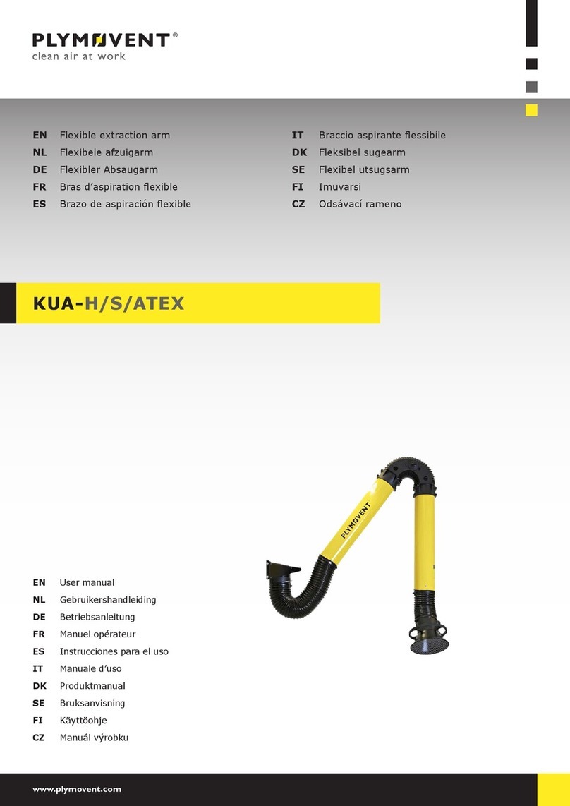
EN Stationarylterunit
EN Installationandusermanual
WALLPRO

000115682/151018/0WallPro 1
EN – ORIGINAL INSTRUCTION
All rights reserved. The information given in this document has been collected for the general convenience of our clients. It has been based on general data pertaining to construction material
properties and working methods known to us at the time of issue of the document and is therefore subject at any time to change or amendment and the right to change or amend is hereby expressly
reserved. The instructions in this publication only serve as a guideline for installation, use, maintenance and repair of the product mentioned on the cover page of this document. This publication is to
be used for the standard model of the product of the type given on the cover page. Thus the manufacturer cannot be held responsible for any damage resulting from the application of this publication
to the version actually delivered to you. This publication has been written with great care. However, the manufacturer cannot be held responsible, either for any errors occurring in this publication or
for their consequences.
To improve comprehension for people whose rst language is not English, we have written parts of this manual in Simplied Technical English (STE). STE is a controlled language
originally developed for aerospace industry maintenance manuals. It offers a carefully limited and standardized subset of English, along with specic writing rules.

000115682/151018/0WallPro 2
ENGLISH Page NEDERLANDS Pag. DEUTSCH Seite
Preface 3
1. Introduction 3
2. Productdescription 4
3. Safetyinstructions 5
4. Installation 6
5. Use 14
6. Maintenance 15
7. Troubleshooting 17
8. Spareparts 18
9. Electricaldiagram 18
10. Disposal 18
CEdeclaration 19
FRANÇAIS Page ESPAÑOL Pág. SVENSKA Sida
ITALIANO Pag.
TABLE OF CONTENTS

000115682/151018/0WallPro EN - 3
PREFACE
Using this manual
Thismanualisintendedtobeusedasaworkofreferencefor
professional,welltrainedandauthoriseduserstobeableto
safelyinstall,use,maintainandrepairtheproductmentioned
onthecoverofthisdocument.
Pictograms and symbols
Thefollowingpictogramsandsymbolsareusedinthismanual:
TIP
Suggestionsandrecommendationstosimplify
carryingouttasksandactions.
ATTENTION
Aremarkwithadditionalinformationfortheuser.A
remarkbringspossibleproblemstotheuser’s
attention.
CAUTION!
Procedures,ifnotcarriedoutwiththenecessary
caution,coulddamagetheproduct,theworkshopor
theenvironment.
WARNING!
Procedureswhich,ifnotcarriedoutwiththe
necessarycaution,maydamagetheproductor
causeseriouspersonalinjury.
CAUTION!
Denotesriskofelectricshock.
WARNING!
Firehazard!Importantwarningtopreventre.
WARNING!
Explosionhazard!Importantwarningtoprevent
explosions.
Personal protective equipment (PPE)
Instructiontouserespiratoryprotectionwhenyou
doservice,maintenanceandrepairjobs,aswellas
duringfunctionaltesting.Werecommendtousea
half-facerespiratoraccordingtoEN149:2001+
A1:2009,classeFFP3(Directive89/686/EEC).
Personal protective equipment (PPE)
Instructiontouseprotectivegloveswhenyoudo
service,maintenanceandrepairjobs.
Text indicators
Listingsindicatedby“-”(hyphen)concernenumerations.
Listingsindicatedby“•”(bulletpoint)describestepsto
perform.
Service and technical support
Forinformationaboutspecicadjustments,maintenanceor
repairjobswhicharenotdealtwithinthismanual,please
contactthesupplieroftheproduct.Hewillalwaysbewillingto
helpyou.Makesureyouhavethefollowingspecicationsat
hand:
- productname
- serialnumber
Youcanndthesedataontheidenticationplate.
1 INTRODUCTION
1.1 Identication of the product
Theidenticationplatecontains,amongotherthings,the
followingdata:
- productname
- serialnumber
- supplyvoltageandfrequency
- powerconsumption
1.2 General description
TheWallProisastationaryweldingfumelterincludingone
(WallProSingle)ortwo(WallProDouble)extractionarmsanda
fan.Thehighlyecientltercartridgeisautomaticallycleaned
bytheintegratedRamAir™pulseamplier,basedonexternal
compressedairsupply.
Theextractionarm(s)canbemounteddirectlytothelterunit
(“DM”types)oratanexternalposition(“EM”types).
TheWallProBasicandWallProBasic PowerPlusarelterunits
withfanbutwithoutextractionarm(s).Theyaresuitablefor
connectiontoanexternaldevice.
1.2.1 Intensity of use
TheWallProSingle“PowerPlus”‒thatcombinesthelargest
armdiameterwithanextrapowerfulfan‒isparticularly
suitableforheavydutyapplicationswithlargequantitiesof
fume,suchasux-coredarcweldingincombinationwithan
automatedweldingprocess.
Extraction
level
Max. extraction
capacity per arm
Application
“Standard” 1000m�/h mediumweldingfume
production
“Power” 1450m�/h medium to heavyfume
production
“PowerPlus” 1800m�/h very heavyfume
production
1.2.2 Congurations
Type Extraction arm Fan
WallProSingle-
160/3 1xKUA-160/3H
FUA-3000
160/4 1xKUA-160/4H
200/3 1xKUA-200/3H
200/4 1xKUA-200/4H
200/3PowerPlus 1xKUA-200/3H FUA-4700
200/4PowerPlus 1xKUA-200/4H
WallProDouble-
160/3 2xKUA-160/3H
FUA-4700
160/4 2xKUA-160/4H
200/3 2xKUA-200/3H
200/4 2xKUA-200/4H
Type Duct connection Fan
WallPro
Basic 1xØ160mm FUA-3000
BasicPowerPlus 1xØ200mm FUA-4700
1.3 Options and accessories
Thefollowingproductscanbeobtainedasanoptionand/or
accessory:
- Dustbinextensionset(metric/imperial)
- WCS-WP|Weldingcablesensor
- Filterdisposalbag(5pieces)|fordust-freelterremoval

000115682/151018/0WallPro EN - 4
- SAS-250straight|Silencer(straight)Ø250mm1
- SAS-315straight|Silencer(straight)Ø315mm2
- LL-5.5/24|Manualon/oswitchonthehood,incl.LED
workinglight
1.4 Technical specications
1.4.1 Filter unit
WallPro Single | Double
Material(housing) electro-zinccoatedsteel
Weight 125kg(excl.armandfan)
Capacityofdustbin 18litres
Filter cartridge
Type CART-O/PTFE/20
Filtermaterial BiCopolyesterwithPTFEmembrane
Filtersurfacearea 20m²
Washable no
Compressed air system
Requiredcompressed
airquality
dryandoil-freeaccordingtoISO
8573-3class6
Inletpressure 5-10bar(75-150PSI)
Requiredpressure 5bar(75PSI)(byintegrated
pressureregulator)
Compressedair
connection
G3/8”(female)
Compressedair
consumption
35Nl(1.2ft³)perpulse
Volumeofcompressed
airtank
9litres(2.4gallon)
Welding fume class
W3 accordingtoISO15012-1:2013
1.4.2 Extraction arm
Type KUA-
160/3H
KUA-
160/4H
KUA-
200/3H
KUA-
200/4H
Weight(incl.
armbracket)
36kg 37kg
Length 3m 4m 3m 4m
Diameter Ø160mm Ø200mm
1.4.3 Fan
Type FUA-3000 FUA-4700
Weight 22kg 35kg
Max.extractioncapacity:
WallPro Single
• 1xKUA-160
• 1xKUA-200
1000m�/h
1450m�/h
n/a
1800m�/h
WallPro Double
• 2xKUA-160
• 2xKUA-200
n/a
n/a
2x1000m�/h
2x1450m�/h
WallPro Basic
• 1inlet(leftorright)
• 2inlets(leftand
right)
1250m�/h
n/a
2100m�/h
2x1550m�/h
1. ForfantypeFUA-3000
2. ForfantypeFUA-4700|Silencerstronglyrecommendedincaseofa
WallPro-Single“PowerPlus”
Powerconsumption:
• 50Hz
• 60Hz
1,1kW(1.5HP)
1,5kW(2HP)
2,2kW(3HP)
2,2kW(3HP)
Motordesign:
• 50Hz
• 60Hz
IEC
NEMA
IEC
NEMA
Energyeciency:
• 50Hz
• 60Hz
IE3
premium
IE3
premium
Fanoutlet(via
transition)
Ø250mm Ø250mm
Noiselevel 75dB(A) 76dB(A)
• withsilencer(ref.
par.1.3)
67dB(A) 71dB(A)
Availableconnection
voltages
400V/3ph/50Hz
208-230V/3ph/60Hz
460V/3ph/60Hz
575V/3ph/60Hz
1.4.4 Control box
Certication
WallPro50Hzversions CE
WallPro60Hzversions UL508A
1.4.5 Dimensions
RefertoFig.Ionpage20.
1.5 Working range
RefertoFig.IIonpage21.
1.6 Ambient and process conditions
Processtemperature:
- min.
- nom.
- max.
5°C(41°F)
20°C(68°F)
70°C(158°F)
Max.relativehumidity 90%
Suitableforoutdooruse no
Refertotheavailableproductdatasheetsfor
detailedproductspecications.
1.7 Transport of the unit
Youcannotholdthemanufacturerliableforanytransportation
damageafterdeliveryoftheproduct.
2 PRODUCT DESCRIPTION
2.1 Components
Theproductconsistsofthefollowingmaincomponentsand
elements:
Fig. 2.1
A Extractionfan3
B Filtercartridge
C Extractionarm4
3. Type:FUA-3000orFUA-4700
4. Type:KUA-160orKUA-200

000115682/151018/0WallPro EN - 5
D Armbracket
E Fanoutlettransition
F Servicepanel
G RamAir™pulseamplier(ltercleaningsystem)
H Indicatorpanel
I Dustbin
J Controlbox
Fig.2.1
A
B
C
H
F
E
G
I
J
D
Maincomponentsandelements
2.2 Operation
TheWallProworksinaccordancewiththerecirculation
principle.Weldingfumeisextractedthroughthehoodofthe
connectedextractionarm(s)bythefan.Thepollutedair
passesthedeectorplate(s)5behindtheinletopening(s)and
iscleanedbytheltercartridge.Theweldingfumeparticles
arecollectedattheoutsideoftheltercartridge.Thecleaned
airisreturnedintheworkshopthroughtheoutletofthefanor
exhaustedtotheatmosphereviaanoutletduct.
2.2.1 Filter cleaning system
TheWallProisprovidedwiththeRamAir™pulseamplier,
whichthoroughlycleanstheltercartridgebycompressedair
pulsesfromtheinsideout.Filtercleaningmainlytakesplace
oine(=whilethefaniso)6.Ifthepressuredropoverthe
ltercartridgereachesthepre-setthresholdvalueduringuse,
anonlinecleaningcycletakesplace.Youcanactivatethelter
cleaningsystemmanuallyaswell(bothoineandonline).
Thedustanddirtparticlesfallintothedustbin.
Refertoparagraph5.3formoredetailsaboutthe
activationofthecleaningsystem.
5. Toprotecttheltercartridgeandtodistributetheairequallyinsidetheunit
6. Oineltercleaningisthemosteectivewayofcleaning.Thecombinationof
oineandonlinecleaningguaranteetheoptimumperformanceoftheunit.
3 SAFETY INSTRUCTIONS
General
Themanufacturerdoesnotacceptanyliabilityfordamageto
theproductorpersonalinjurycausedbyignoringofthesafety
instructionsinthismanual,orbynegligenceduring
installation,use,maintenance,andrepairoftheproduct
mentionedonthecoverofthisdocumentandany
correspondingaccessories.
Specicworkingconditionsorusedaccessoriesmayrequire
additionalsafetyinstructions.Immediatelycontactyour
supplierifyoudetectapotentialdangerwhenusingthe
product.
The user of the product is always fully responsible for
observing the local safety instructions and regulations.
Observe all applicable safety instructions and
regulations.
User manual
- Everyoneworkingonorwiththeproduct,mustbefamiliar
withthecontentsofthismanualandmuststrictlyobserve
theinstructionstherein.Themanagementshouldinstructthe
personnelinaccordancewiththemanualandobserveall
instructionsanddirectionsgiven.
- Donotchangetheorderofthestepstoperform.
- Keepthemanualwiththeproduct.
Users
- Theuseofthisproductisexclusivelyreservedtoauthorised,
trainedandqualiedusers.Temporarypersonneland
personnelintrainingcanonlyusetheproductunder
supervisionandresponsibilityofskilledengineers.
- Stayalertandkeepyourattentiontoyourwork.Donotuse
theproductwhenyouareundertheinuenceofdrugs,
alcoholormedicine.
- Theproductisnottobeusedbychildrenorpersonswith
reducedphysical,sensoryormentalcapabilities,orlackof
experienceandknowledge,unlesstheyhavebeengiven
supervisionorinstruction.
- Childrenmustbesupervisednottoplaywiththeproduct.
Intended use7
Theproducthasbeendesignedexclusivelyforextractingand
lteringgasesandparticleswhicharereleasedduringthe
mostcommonweldingprocesses.Usingtheproductforother
purposesisconsideredcontrarytoitsintendeduse.The
manufactureracceptsnoliabilityforanydamageorinjury
resultingfromsuchuse.Theproducthasbeenbuiltin
accordancewithstate-of-the-artstandardsandrecognised
safetyregulations.Onlyusethisproductwhenintechnically
perfectconditioninaccordancewithitsintendeduseandthe
instructionsexplainedintheusermanual.
Technical specications
Donotchangethespecicationsgiveninthismanual.
Modications
Modicationof(partsof)theproductisnotallowed.
Installation
- Theinstallationofthisproductisexclusivelyreservedto
authorised,trainedandqualiedengineers.
- Theelectricconnectionmustbeexecutedinaccordancewith
thelocalcodesandrequirements.Ensurecompliancewith
theEMCregulatoryarrangements.
7. “Intendeduse”asexplainedinEN-ISO12100-1istheuseforwhichthe
technicalproductissuitedasspeciedbythemanufacturer,inclusiveofhis
directionsinthesalesbrochure.Incaseofdoubtitistheusewhichcanbe
deducedfromtheconstruction,themodelandthefunctionofthetechnical
productwhichisconsiderednormaluse.Operatingthemachinewithinthe
limitsofitsintendedusealsoinvolvesobservingtheinstructionsintheuser
manual.

000115682/151018/0WallPro EN - 6
- Duringinstallation,alwaysusePersonalProtective
Equipment(PPE)toavoidinjury.Thisalsoappliestopersons
whoentertheworkareaduringinstallation.
- Usesucientclimbinggearandsafetyguardswhenworking
onahigherlevelthan2metres(localrestrictionsmay
apply).
- Donotinstalltheproductinfrontofentrancesandexits
whichmustbeusedforemergencyservices.
- Mindanygasandwaterpipesandelectriccables.
- Makesurethattheworkspaceiswellilluminated.
- Stayalertandkeepyourattentiontoyourwork.Donot
installtheproductwhenyouareundertheinuenceof
drugs,alcoholormedicine.
- Aircontainingparticlessuchaschromium,nickel,beryllium,
cadmium,leadetc.,shouldneverberecycled.Thisairmust
alwaysbebroughtoutsidetheworkingarea.
Use
WARNING!
Firehazard!Donotusetheproductfor:
- polishingapplicationsincombinationwith
grinding,weldingoranyotherapplicationthat
generatesparks(bersfrompolishingorabrasiveapdisks
arehighlyammableandposeahighriskoflterreswhen
exposedtosparks)
- arc-airgouging
- extractingand/orlteringammable,glowingor
burningparticlesorsolidsorliquids
- extractingand/orlteringofaggressivefumes
(suchashydrochloricacid)orsharpparticles
- extractingand/orlteringdustparticleswhichare
releasedwhenweldingsurfacestreatedwith
primer
- suckingcigarettes,cigars,oiledtissues,andother
burningparticles,objects,andacids
WARNING!
Explosionhazard!Donotusetheproductfor
explosion-hazardousapplications,e.g.:
- aluminiumlasercutting
- grindingaluminiumandmagnesium
- explosiveenvironmentsorexplosivesubstances/
gases
WARNING!
Donotusetheproductfor:
- extractionofhotgases(morethan70°C/158°F
continuously)
- amespraying
- oilmist
- heavyoilmistinweldingfume
- extractionofcement,sawdust,wooddustetc.
- Inspecttheproductandcheckitfordamage.Verifythe
functioningofthesafetyfeatures.
- Duringuse,alwaysusePersonalProtectiveEquipment(PPE)
toavoidinjury.Thisalsoappliesforpersonswhoenterthe
workarea.
- Checktheworkingenvironment.Donotallowunauthorised
personstoentertheworkingenvironment.
- Protecttheproductagainstwaterandhumidity.
- Makesuretheroomisalwayssucientlyventilated;this
appliesespeciallytoconnedspaces.
- Makesurethattheworkshop,inthevicinityoftheproduct,
containssucientapprovedreextinguishers(suitablefor
reclassesABC).
- Donotleaveanytoolsorotherobjectsinorontheunit.
- Theweldingcurrentreturncircuitbetweentheworkpiece
andtheweldingmachinehasalowresistance.Thusavoid
connectionbetweentheworkpieceandtheWallPro,sothat
thereisnopossibilityoftheweldingcurrentowingbackto
theweldingmachineviatheprotectiveearthconductorof
theWallPro.
Service, maintenance and repairs
- Obeythemaintenanceintervalsgiveninthismanual.
Overduemaintenancecanleadtohighcostsforrepairand
revisionsandcanrendertheguaranteenullandvoid.
- AlwaysusePersonalProtectiveEquipment(PPE)toavoid
injury.Thisalsoappliesforpersonswhoentertheworkarea.
- Makesuretheroomissucientlyventilated.
- Usetools,materials,lubricantsandservicetechniqueswhich
havebeenapprovedbythemanufacturer.Neveruseworn
toolsanddonotleaveanytoolsinorontheproduct.
- Usesucientclimbinggearandsafetyguardswhenworking
onahigherlevelthan2metres(localrestrictionsmay
apply).
- Cleantheareaafterwards.
ATTENTION
Service,maintenanceandrepairsmustbe
performedinaccordancewithdirectiveTRGS560
andTRGS528byauthorised,qualiedandtrained
persons(skilled)usingappropriateworkpractices.
ATTENTION
Beforeyoucarryoutservice,maintenanceand/or
repairjobs:
- fullydisconnecttheunitfromthemains
Personal protective equipment (PPE)
Wearrespiratoryprotectionandprotective
glovesduringservice,maintenanceand
repairs.
WARNING
Theindustrialvacuumcleanerthatyouuseduring
serviceandmaintenancemustmeetdustclassH
accordingtoEN60335-2-69orHEPAclass
(eciency≥99.97%at0.3µm).
4 INSTALLATION
4.1 Tools and requirements
Youneedthefollowingtoolsandrequirementstoinstallthe
unit:
- basictools
- fork-lifttruck
- electricaltools
4.1.1 To be sourced locally
General
- Wallmountinghardwareforthelterunit8
- Mainscable:4G1.5
- typeH05VV-F(PVC,standardcable);or:
- typeH05RN-F(rubber,forheavyduty,e.g.whenpartof
thecableisontheoor)
- Motorcable:4G1.5
- typeH05VV-F(PVC,standardcable);or:
- typeH05RN-F(rubber,forheavyduty,e.g.whenpartof
thecableisontheoor)
- QuickdisconnectcouplingwithamaleG3/8”thread
- Compressedairhose
WallPro type “EM” only
- Wallmountinghardwareforthearmbracket(s)9
- DuctingØ160mm(6in.)/Ø200mm(8in.)10betweenthe
lterunitandthearmbracket(s)
8. Thetypeofhardwaredependsonthewalltype
9. Formountingatanexternalposition;thetypeofhardwaredependsonthe
walltype
10. Dependingonthetypeofextractionarm
000115682/151018/0WallPro EN - 7
WallPro “UL” types11 (60Hz versions) only
- Componentsnecessaryforelectricalinstallationaccordingto
ULandfederal,stateorlocalwiringregulations
Option
Incaseofadustbinextensionset:
- ductØ200mmor8in.
4.2 Unpacking
Makesurethattheproductiscomplete.Thepackagecontains:
Filter unit
- Filterunit(withoutsidepanels),incl.10mcable12
- Wallbracket
- Dustbinset
- Airhose(lterpressure)2x10m
- SealApplicator(sealassemblylubricant)
- Filterdisposalbag(5pieces)
- Mountingmaterial
Side panel (2)
- Sidepanel
Mounting kit
- Mountingandductingmaterial(types“DM”only)
- Inletange+non-returnvalve
Additionally for “EM” congurations in 60Hz:
• Ductadaptermetric-imperial13
(WallProSingle:1piece|WallProDouble:2pieces)
Foranoverviewofthemountingmaterialper
specicconguration,refertoFig.IVonpage22.
Extraction arm (1 or 2)
Refer to the installation manual of the KUA-160 or KUA-200,
that is supplied with the product.
Extraction fan
- Fan
- Fanoutlettransition(fromrectangulartoroundØ250mm)
Control equipment
- Controlbox
4.3 Stationary lter unit
ATTENTION
Itisimportanttofollowthemountingsequenceas
writteninthis(4.3)andthenext(4.4)chapter.
Thetablebelowexplainsthevariouscongurationtypes.
WallPro type Explanation
Single- 1extractionarm
Double- 2extractionarms
Basic noextractionarm(s)
160/ ArmdiameterØ160mm
200/ ArmdiameterØ200mm
3- Armlength3m
4- Armlength4m
DM Directmount
EM Externalmount
11. The“UL”certicationappliestothecontrolbox
12. Forconnectionwiththecontrolbox
13. FromØ160toØ6in./Ø200toØ8in.,dependingontheconguration
CE Controlbox:CEmarking
UL Controlbox:ULcertied
Anumberofinstallationstepsareonlyapplicabletooneor
morespeciccongurations.Theseareindicatedatthe
beginningofacertainparagraph.Thegrey/emptycellsare
universal.
Someexamples:
In case of: Applies to all
“DM” typesDM
In case of: Applies to all
WallPro Single
types and all
“EM” types
WallProSingle-
EM
Writeyourcongurationtypebelow.
WallPro type
TIP
Forstableassemblyconditions,werecommendto
leavethelterunitonthepallet(untilstep4.6).
4.3.1 Reinforcement plate
In case of:
DM
IncaseofaWallProSingle“DM”(directmount)youmust
installareinforcementplatebehindthelowerpartoftheside
paneltocarrytheweightofthearmbracket+extractionarm.
ThepackageoftheWallProDouble“DM”containstwo
reinforcementplatesforbothsidesofthelterhousing.
IncaseofaWallProtype“EM”(externalmount),
wheretheextractionarmismountedseparately
fromthelterunit,thereinforcementplateisnot
necessary.Inthatcase,proceedwithpar.4.3.2.
Toinstallthereinforcementplate,dothefollowing.
Fig. 4.2
• Insertthe4cagenutsM12fromtheinsideinthe
correspondingpositionsoftheplate;
- KUA-160/armØ160mm:innerpositions(A)
- KUA-200/armØ200mm:outerpositions(B)
Fig.4.2
A
B
Cagenuts

000115682/151018/0WallPro EN - 8
Fig. 4.3
• Determineonwhichside14youwanttoinstalltheextraction
arm(leftorright).
• Installthereinforcementplateonthatsideofthelterunit
withthe7angeboltsM6x16.
Fig.4.3 Mountingofthereinforcementplate
4.3.2 Inlet ange + non-return valve (assembly)
Applies to all types of units
Youmustinstalltheassembly,thatconsistsofaninletange
withnon-returnvalve,onthesidepanelofthelterunit.In
caseofaWallProDouble,youmustinstallanassemblyon
bothsidepanels.
Thesidepanelsareuniversal,soyoucaninstall
themeitherleftorright.
Toinstalltheassembly,dothefollowing.
Fig. 4.4
• Dependingonthemountingposition15,determinethe
insideofthesidepanel.
• Putsealingmaterial(E)aroundtheinletopeningonthe
insideofthesidepanel.
• Inserttheassemblyfromtheinsideofthepanelthrough
theopening.Makesurethattheaxisofthenon-return
valveisinverticalposition(B).
• Attachtheassembly(A)tothesidepanelwiththe6bolts
M6,washersandnuts.
• Securethenon-returnvalvetotheinletangewith2
self-tappingscrews(F+G).Twosmallholesintheinlet
angeindicatethecorrectposition.Makesurethatyou
installonescrewontopandtheotheroneatthebottomof
theassembly.
• Makesurethatthenon-returnvalvecanfullyopen.
In case of a LL-5.5/24 | Manual on/o switch on the
hood, incl. LED working light (option)
• InstallthecableglandM16+nutM16(C).
If not:
• InstallthescrewplugM16+nutM16(D).
14. IncaseofaWallProDoubleyoumustinstallareinforcementplateonboth
sides
15. Ontheleftorrightsideofthelterunit
A
B
E
F
G
C
D
A
B
E
F
G
C
D
Fig.4.4 Inletange+non-returnvalve(assembly)
4.3.3 Side panel
In case of:
DM
Makesurethatyouhavethe4boltsM12athand
thatyouneedtoinstallthearmbracket.
ForthecorrectuseofSealApplicator,refertothe
instructionsheetthatissuppliedwiththespray
bottle.
RefertoFig.Vonpage23fortheexactmounting
positionofthesidepanelwithrespecttothecover
plates(top+bottom).
Fig. 4.5
• (1)Removethebackingmaterialoftheseals.
• (2)SpraySealApplicatorlubricantontheseals16.
• (3)Putthesidepanelwithin 60 seconds17onthelter
unit.
• (4)Alignthesidepanelwiththe4boltsM12x30intothe
cagenutsandpartlytightenthem18.
• (5)Installthesidepanelwiththe24boltsM6x16+sealing
washersM6.
• (6)Disassemblethe4boltsM12x30.
16. BytheuseofSealApplicatoryoucanslightlyshiftthesidepaneltogetthe
rightposition.Afterapprox.60secondsthelubricantisdrysoyoucannotshift
anymore.
17. Afterapprox.60secondsSealApplicatorlubricantlosesitsfunctionsandyou
cannotshiftanymore.
18. Youmustremovethemlaterontoinstallthearmbracket.

000115682/151018/0WallPro EN - 9
Fig.4.5
<60 s
4x
24x
1
3
2
5
46
Mountingofthesidepanel
In case of:
WallProDouble- DM
• Repeattheinstructionsofparagraph4.3.3toinstallthe
othersidepanel.
In case of:
WallProSingle-
WallProBasic
EM
• Repeattheinstructionsofparagraph4.3.3toinstallthe
sidepanel19,withtheexceptionofsteps(4)and(6).To
alignthepanel,puttwoboltsM6x16inthetopcorners
rst.Theninstalltheremaining22bolts.
4.3.4 Arm bracket
In case of:
DM
ATTENTION!
Makesurethatyouhaveinstalledthereinforcement
platebehindthesidepanel;refertoparagraph
4.3.1.
Fig. 4.6
• Installthearmbracketonthelterunitwith4bolts
M12x3020andwashersM12.
19. WallProSingle:blindsidepanel|WallPro“EM”:sidepanelwithinletange+
non-returnvalve
20. Theonesyouusedtoalignthesidepanelinstep4.3.3
Fig.4.6 Mountingofthearmbracket
In case of:
WallProDouble- DM
Ifapplicable:
• Dothesameprocedurefortheotherarmbracket.
In case of:
EM
Recommendedinstallationheightofthearmbracket:at
approx.2-2,3m(6.5-7.5ft)fromtheoor(topofthewall
bracket).Alsorefertothefootnoteonpage10.
• Installthearmbracket(s)atthedesiredpositiononthe
wall,preferablyascloseaspossibletothelterunit.
4.4 Extraction fan
Dependingontheselectedconguration,thepackagecontains
afantypeFUA-3000orFUA-4700.Youcaninstallthefanin
dierentpositionstogetthedesiredoutletdirection;
- FUA-3000:6possibledirections
- FUA-4700:2possibledirections(leftandright)
RefertoFig.IIIonpage21foranoverviewofthe
possibleoutletdirections.
Toinstallthefan,dothefollowing.
Fig. 4.7
• Putadhesiverubberstrip(A)aroundtheinletopeningon
topofthelterunit.Makesurethatthestripdoesnot
entirelycovertheholes.
• Disassembletheservicepanel(refertoFig.2.1F).
Fig.4.7
A
Adhesiverubberstrip

000115682/151018/0WallPro EN - 10
Ifyouintendtoconnectanoutletductand/or
silencertothefan,werecommendtoinstallthe
necessaryoutlettransition(fromrectangularto
round)rst.Refertoparagraph4.10.1forthe
installationinstruction.
Theinletangeofthefancontains6bolts.Thepositionsof
theseboltscorrespondwiththe6holesontopofthelter
unit;2largeand4smallholes.Toinstallthefan,youonly
needthe4smallholes.
Fig. 4.8
• Determinethedesiredoutletdirectionofthefan.
• Determinewhich4boltscorrespondwiththe4smallholes
inthelterunit.
• Removethese4boltsfromtheinletange21.
• (1)Put4positioningstuds(A)atthepositionofthe
removedbolts.
• (2)Carefullyputthefanontopofthelterunit.Makesure
toputthepositioningstudsinthe4holes.
• Put4angelocknutsM8(B)fromtheinsideonthestuds
andtightenthem.
• Installtheservicepanel.
Fig.4.8
A (4x)
B (4x)
2
1
Positioningstuds
4.5 Compressed air connection (lter unit)
ATTENTION
Thecompressedairmustbedryandoil-free
accordingtoISO8573-3class6.
Fig. 4.9
• InstallaquickdisconnectcouplingwithamaleG3/8”
threadtothefemaletting(A)ontheunit.
• Installacompressedairsupplyhosetothiscoupling.
• Connecttheairhoses22intheconnectors+and−(B+C).
21. Youdonotneedthesefourboltsanymore.Theothertwoboltsremainunused
butmuststayintheinletange
22. Thedierentcolourssimplifycorrectconnectiontothecontrolbox
Fig.4.9
AB
E
C
Compressedairconnection(rearoftheunit)
4.6 Wall bracket
ATTENTION!
Beforeyouinstallthewallbracket,makesurethat
thewallormountingstructureisstrongandrigid
enough.Refertosection1.4fortheweightofthe
lterunit,fanandextractionarm(s).
• RefertoFig.VIonpage23fortherecommended
installationheight23andtheholepatternofthewall
bracket.
Toinstallthewallbracket,dothefollowing.
Fig. 4.10
• Thewallbracketistemporarilyattachedtotheunitbya
cabletie.Cutthecabletie.
• Installthewallbracket(B)tothewallormounting
structure.Useall4mountingpoints.Makesurethatthe
wallbracketislevel.
• Lifttheunitandinsertthehooks(A)intheslotsofthewall
bracket.
• SecuretheunittothewallbracketwiththeboltsM10x30,
locknutsM10andwashersM10(C).
Fig.4.10
B
A
C
Mountingofthewallbracket
23. Incaseofan“EM”type,theinstallationheightislesscritical,sincethe
extractionarmsaremountedseparatelyfromthelterunit.However,toavoid
bends(=pressuredrop)intheducting,werecommendtoinstallthelterunit
attheindicatedheightandtoconnectthearmsascloseaspossibletothe
lterunit.

000115682/151018/0WallPro EN - 11
4.7 Extraction arm
Forassemblyoftheextractionarm(s),refertotheinstallation
manualoftheKUA-160orKUA-200,thatissuppliedwiththe
product.
4.7.1 LL-5.5/24 | Manual on/o switch on the hood,
incl. LED working light (option)
• InstalltheLL-5.5/24inthehoodoftheextractionarmin
accordancewiththeinstructionsheetthatissuppliedwith
theproduct.
Subsequently:
Fig. 4.11
• Feedthecablethroughtheextractionarmtotherotating
ange(A).
• Feedthecablethroughthegrommetintothecablegland
(B).
• Tightenthecablegland.
Fig.4.11
B
A
Grommet+cablegland
Fig. 4.12
• Releasethehopper(D)togetaccesstotheinsideofthe
unit.
• “DM”typesonly:Feedthecablethroughthereinforcement
plate(A).
• Removetheblindplug(C)fromthenearest(leftorright)24
cablegland(B),justbelowtheindicatorpanel.
• Feedthecablethroughthecablegland(B)insidetheunit.
• Tightenthecablegland.
24. IncaseofaWallProDouble:usetheleftcableglandfortheleftarmandvice
versa
Fig.4.12
B
A
DM
C
D
Cableconnection
Fig. 4.13
• Removethecoveroftheindicatorpanel.
• Cutthecabletotheappropriatelength.
• Connectthecableasindicatedbelow.Thewirenumbers
(#)correspondwiththoseontheinstructionsheetthatis
suppliedwiththeLL-5.5/2425.
Wire# Colour Connection
03 red 1
04 black 2
05 grey 2
06 blue 3
H6
H5
Working
Light
External
start/stop
1 22 3 4 5 6 7 8
12 2345678
X1
X1
Fig.4.13Cableconnectioninsideindicatorpanel
ATTENTION!
Beforeyouproceed,makesurethatallcableglands
arefullytightened,topreventleakageofdust.
4.7.2 Inlet ducting
In case of:
DM
25. Manualon/oswitchonthehood,incl.LEDworkinglight

000115682/151018/0WallPro EN - 12
Fig. 4.14
• Putadhesiverubberstrip(G)aroundtheopeningofthe
armbracket.Makesurethatthestripdoesnotentirely
covertheholes.
• Putthemountingange(D)overtheductange(C).
• Putthebend(E)intotheductange(C).
• Puttheothersideofthebend(E)intotheinletange26
(B).
• Installthemountingangetothearmbracketwith4x
boltsM8with8xwashersand4xlocknuts(F),thatare
suppliedwiththeextractionarm.
• Makesurethatallconnectionsareairtight.
Fig.4.14
4x
B
C
A
EM
D
E
F
G
Inletducting
In case of:
EM
• Ifapplicable27:installtheductadaptermetric-imperial(A)
intheinletange(B).
• Installducting28betweenB(orA)andtheextractionarm.
• Makesurethatallconnectionsareairtight.
4.8 Dustbin
Toinstallthedustbin,dothefollowing.
• Installthedustbinassembly(C)tothehopper(A)withthe
suppliedductclamp(B).
• Turntherotaryknob(D)inverticalpositiontoopenthe
shut-ovalve.
A
C
B
D
Fig.4.15Mountingofthedustbin
26. Inletange+non-returnvalve(assembly)
27. Incaseof60Hzcongurationswithanimperialductsize(Ø6in.orØ8in.)
28. Ø160mm/6in.orØ200mm/8in.,dependingontheinletdiameter
4.8.1 Dustbin extension set (option)
Foreasymaintenance,youcaninstallthedustbinontheoor
viathedustbinextensionset.
Thedustbinextensionsetconsistsofthefollowing
components:
Fig. 4.10
A Ductconnectionring
B ExtensionductØ200mm/Ø8in.(tobesourcedlocally)
C Hoseclamp
D Rubbercollar
E PVChose
F Hoseclamp
G Rubbercollar
H Hoseconnectionring
I Ductclamp
Fig.4.10
A
B
C
D
E
F
G
H
I
Dustbinextensionset
• Installthedustbinextensionsetbetweenthelterunitand
thedustbinwiththesuppliedcomponents+extension
duct.
• Usetherubbercollarstomaketheconnectionsairtight.
4.9 Control box
4.9.1 Connections
Refertotheseparatelysuppliedelectricaldiagram
fortheelectricconnections.Refertoparagraph
4.1.1fortherequiredcablespecications.
In case of:
UL
Componentsnecessaryforelectricalinstallation
accordingtoULandfederal,stateorlocalwiring
regulationsarenotincludedandmustbesourced
locally.
Fig. 4.20
• Installthecontrolboxatanappropriateposition.
• Connectthecontrolboxtothefan(B).
• Connectthecontrolcable(C)fromthelterunittothe
controlbox(refertoFig.4.9E).

000115682/151018/0WallPro EN - 13
• Installtheairhoses(D).Makesurethatthe+and–
correspondswiththe+and–connectionontherearofthe
lterunit29(refertoFig.4.9B+C).
In case of:
UL
Defaultconnectionofthetransformeris600V(E).Depending
onthecongurationofthefanmotorandthelocalpower
supply,youmustchangetheconnection.
• Ifapplicable:changetheconnectionofthetransformer(E).
Applies to all types of units
• Connectthecontrolboxtothemains(A).
A B C D
POWER ON
BEDRIJFSGEREED
STROMVERSORGUNG EIN
SOUS TENSION
TENSIÓN ELÉCTRICA ON
FILTER CLEANING
FILTERREINIGING
FILTERREINIGUNG
DÉCOLMATAGE DU FILTRE
LIMPIEZA DEL FILTRO
START/STOP FAN
VENTILATOR AAN/UIT
VENTILATOR EIN/AUS
VENTILATEUR MARCHE/ARRÊT
ARRANQUE/PARO VENTILADOR
FILTER CLOGGED
FILTERVERSTOPT
FILTER GESÄTTIGT
FILTRE OBSTRUÉ
FILTRO OBSTRUIDO
A
B
C
D
E
Connections:
A Mainscable to mains
B Motorcable to fan
C Controlcable to lterunit
D Airhoses to lterunit
E
E Transformerconnection(WallPro“UL”types/60Hzonly)
Fig.4.20Controlbox
In case of:
UL
Dependingontheconnectionvoltageofthefan,youmustset
thethermalrelayinsidethecontrolboxtothecorrectvalue.
Fig. 4.21
• Determinethethermalrelaysettingthatbelongstoyour
speciccongurationinthetablebelow.
• Adjustthethermalrelaytothecorrectsettingwitha
Phillips-headscrewdriver.
29. Mindthecolourofthehoses
UL
WallPro Fan type Conn.
voltage
Power Thermal relay
Range Setting
Single FUA-3000 230 V 2HP 4.0-6.3A 5.2 A
460 V 2HP 2.2-3.2A 2.4 A
575 V 2HP 1.7-2.4A 2.1 A
PowerPlus FUA-4700 230 V 3HP 7.5-10.5A 8.8 A
Double 460 V 3HP 4.0-6.3A 4.0 A
575 V 3HP 2.2-3.2A 2.9 A
Fig.4.21Thermalrelaysetting
4.9.2 Pressure setting
Applies to all types of units
Thedierentialpressureswitchinsidethecontrolpanel
activatestheltercleaningsystemassoonasthepressure
dropreachesthethresholdvalue.Thisguaranteesthe
optimumperformanceoftheunit.Thepressuresetting
dependsonthespeciccongurationandmotorfrequency.
• Determinetherequiredthresholdvalue(pressureinmbar)
fromthetablebelow.
WallPro Arm
Ø
Fan power Pressure
setting (mbar)
50 Hz 60 Hz 50 Hz 60 Hz
Single 160 1,1kW 1,5kW(2HP) 9 15
200 1,1kW 1,5kW(2HP) 13 19
2,2kW(3HP)(PowerPlus) 19 27
Double 160 2,2kW 2,2kW(3HP) 14 23
200 2,2kW 2,2kW(3HP) 18 25
Basic*) n/a 1,1kW 1,5kW(2HP) 9 15
2,2kW(3HP)(PowerPlus) 19 27
*)As the manufacturer does not know in which conguration the
WallPro Basic is installed, you must use these pressure setting values
as a guideline only. The optimum pressure setting will be a matter of
experience. The lower the pressure setting, the sooner the lter
cleaning system is activated.
In case of early activation: increase the pressure setting.
In case of late activation: decrease the pressure setting.
Recommended step size to increase/decrease is 3 mbar.
Fig. 4.22
• Demountthetransparentcoverofthedierentialpressure
switch.
• Settherequiredpressureaccordingtothetable.
• Installthecover.
• Closeandlockthecontrolbox.

000115682/151018/0WallPro EN - 14
Fig.4.22
m
b
a
r
6
1
0
1
5
2
0
2
5
3
0
3
5
4
0
4
5
5
0
Dierentialpressureswitch
4.10 Fan outlet
Thefanhasarectangularoutletwithgridforrecirculation30of
thelteredairintotheworkshop.Inthatcasethesuppliedfan
outlettransition–fromrectangulartoround–isredundant.
Formountingtotheoptionalsilencer31oranoutletduct,you
mustinstallthefanoutlettransitionrst.Thetablebelow
showsthevariousoutletpossibilities.
Fanoutlet
Recirculation
Outlet
transition
Outletduct Exhausttoatmosphere
Silencer Recirculation
Outletduct Exhaustto
atmosphere
4.10.1 Fan outlet transition
Fig. 4.23
• Determinethedesiredoutletconguration.
Incaseofdirectrecirculationoftheair,theoutlettransitionis
redundant.
Ifapplicable:
• Disassemblethegrid(A).
• Installtheoutlettransition(B)tothefanwiththeboltsand
nutsofthegrid.
• Installthetheoptionalsilencerand/ortheoutletductto
theoutlettransition.
30. Makesurethatrecirculationisallowedbystateorlocalregulations
31. Refertoparagraph1.3
Fig.4.23
A
B
Fanoutlettransition
4.11 Commissioning checklist
# Check Ref.
par.
OK
1. Areallcablescorrectlyinstalled? 4.9.1
2. Aretheairhoses(+and–)correctly
installed?
4.9.1
3. Isthedirectionofrotationofthefan
correct?Anarrowonthefanhousing
indicatesthecorrectdirection.
4. Isthelterunitconnectedtothe
compressedairsupply?
4.5
5. In case of the optional LL-5.5/24 (on/o
switch + working light):
Areallcableglandsfullytightened?
4.7.1
6. Isthepressuresettingcorrect? 4.9.2
7. Istheshut-ovalveofthedustbin
open?
4.8
5 USE
WARNING!
Firehazard!Donotusetheproductforpolishing
applicationsincombinationwithgrinding,weldingor
anyotherapplicationthatgeneratesparks.
Refer to chapter 3 / Safety instructions / Use.
5.1 Control panel
TheWallProhasaseparatecontrolbox.Controlsand
indicators:
Fig. 5.1
A POWERON|whiteLEDthatindicatesthatthecontrolbox
isconnectedtothemainsandthatthepowerison
B FILTERCLOGGED|redLEDthatindicatesthatitis
necessarytoreplacetheltercartridge
C Mainswitch|to(de-)energizetheentireunit
D FILTERCLEANING|bluepushbuttonwithLEDtoactivate
theltercleaningsystemmanually
E START/STOPFAN|greenpushbuttonwithLEDtostartand
stopthefan

000115682/151018/0WallPro EN - 15
Fig.5.1
A B C D
POWER ON
BEDRIJFSGEREED
STROMVERSORGUNG EIN
SOUS TENSION
TENSIÓN ELÉCTRICA ON
FILTER CLEANING
FILTERREINIGING
FILTERREINIGUNG
DÉCOLMATAGE DU FILTRE
LIMPIEZA DEL FILTRO
START/STOP FAN
VENTILATOR AAN/UIT
VENTILATOR EIN/AUS
VENTILATEUR MARCHE/ARRÊT
ARRANQUE/PARO VENTILADOR
FILTER CLOGGED
FILTERVERSTOPT
FILTER GESÄTTIGT
FILTRE OBSTRUÉ
FILTRO OBSTRUIDO
A
B
C
D
E
Controlpanel
Thelterunititselfcontainsanindicatorpanelwithtwopilot
lights,thatcorrespondwiththeonesonthecontrolbox:
Fig. 5.1
A RedLEDon|indicatesthatitisnecessarytoreplacethe
ltercartridge
B GreenLEDon|indicatesthatthefanisrunning
Fig.5.1
A
B
C
D
E
A
B
Indicatorpanel
5.2 Use
ATTENTION
Duringuse,makesurethattheshut-ovalveis
open.RefertoFig.4.15C(rotaryknobinvertical
position).
Refer to Fig. 5.1
• Positionthehoodoftheextractionarmat400-800mm
(16-32in.)fromthesourceofpollution.RefertoFig.VII
onpage23forthecorrectposition.
• Makesurethattheshut-odamperinsidetheextraction
armisopen(refertoFig.VIIIonpage23).
• Makesurethatthemainswitch(C)ison.
• PushtheSTART/STOPFAN(E)buttontoactivatethefan32.
• Startwelding.
• Whentheweldingpositionchanges,movethehoodtothe
correctpositioninrelationtotheweld.
WARNING
Tokeeptheweldingfumeawayfromthebreathing
zoneofthewelder,makesurethatallfumeis
extractedthroughthehood.
• Puttheunitoapprox.20secondsafteryouhavenished
welding.
32. Optionstoactivatethefan:on/oswitchonthehoodoftheextractionarmor
automaticallyviaaweldingcablesensor(WCS-WP)
Duringuse,doaregularcheckonthestatusoftheredLED
(FILTERCLOGGED).WhenthisLEDison,itisnecessaryto
replacetheltercartridge(refertoparagraph6.2).
Topreventunnecessarylterreplacement,make
surethat:
- compressedairisavailableandconnected
- thepressuresettingiscorrect(refertoparagraph
4.9.2)
5.3 Filter cleaning system
Theltercleaningsystemcanbeactivatedinthreedierent
waysandtakesplaceeitheroine(fano)oronline(fanon).
Activation of lter cleaning system
Oine
Online
# cleaning
cycles
Duration
(sec.)
Automatically atfanshutdown √ 1 60
pressurecontrolled √ 1 60
Manually bypushbutton √ √ 1 60
Onecleaningcycleconsistsofsixcompressedairpulses.
Automatically | at fan shutdown
After≥30minutesof(intermittentorcontinuous)operation,
onecleaningcycletakesplacewhenthefaniso,withadelay
timeof15seconds.Ifthefanstartsrunningagainwithin
those15seconds,theltercleaningsystemwillnotbe
activated.
Automatically | pressure controlled
Adierentialpressureswitchactivatestheltercleaning
systemimmediatelywhenthepressuredropreachesthe
thresholdvalueduringuse.
Manually | by push button
Toactivatetheltercleaningsystemmanually,dothe
following:
• PushandholdtheFILTERCLEANINGbutton(ref.Fig.5.1D)
for5seconds.
6 MAINTENANCE
6.1 Periodic maintenance
Theproducthasbeendesignedtofunctionwithoutproblems
foralongtimewithaminimumofmaintenance.Inorderto
guaranteethissomesimple,regularmaintenanceandcleaning
activitiesarerequiredwhicharedescribedinthischapter.If
youobservethenecessarycautionandcarryoutthe
maintenanceatregularintervals,anyproblemsoccurringwill
bedetectedandcorrectedbeforetheyleadtoatotal
breakdown.
WARNING
Overduemaintenancecancausere.
Theindicatedmaintenanceintervalscanvarydependingon
thespecicworkingandambientconditions.Thereforewe
recommendtothoroughlyinspectthecompleteproductonce
everyyearbesidetheindicatedperiodicmaintenance.Forthis
purposecontactyoursupplier.

000115682/151018/0WallPro EN - 16
Component Action Frequency:
every X months
X=6 X =12
Filter unit
Dustbin Empty;refertoparagraph6.3 *)
Housing Cleantheoutsidewitha
non-aggressivedetergent
X
Cleantheinsidewithanindustrial
vacuumcleanerandremovedust
fromtheltercompartment
X
Checksealingmaterialofthe
door.Replaceifnecessary
X
Mainscord Checkfordamage.Repairor
replaceifnecessary
X*)
Extraction fan
Fanhousing Checkforencrustedparticles.
Cleanifnecessary
X
Extraction arm
Tubes Cleantheoutsidewitha
non-aggressivedetergent
X
Cleantheinsidethoroughly X
Flexible
hoses
Checkforcracksordamages.
Replaceifnecessary
X
Hood Checkthemovementofthehood.
Ifnecessary,adjustthefriction;
refertoparagraph6.4
X
Arm
movement
Checkhorizontal,verticaland
diagonalarmmovement.If
necessary,adjustthefriction;
refertoparagraph6.4
X
*) During use, you must check the level of contents in the dustbin
regularly. The emptying frequency depends on the intensity of use and
will be a matter of experience. In the initial stage, do a check on the
level of contents of the dustbin 2 times per month.
6.2 Filter replacement
WhentheredLED(FILTERCLOGGED)ison,youmustreplace
theltercartridge.
Personal protective equipment (PPE)
Wearrespiratoryprotectionandprotective
gloveswhenyoureplacethelter
cartridge.
WARNING
Donotreplacetheltercartridgewhilethefanis
running.
Toreplacetheltercartridge,dothefollowing.
ScantheQRcodetowatchashort
demoaboutlterreplacement.
Fig. 6.1
• De-energizetheunit.
• Turntherotaryknob(A)inhorizontalpositiontoclosethe
shut-ovalve.
• Loosenthequickreleaseclamp(F)andremovethedustbin
(G).
• Loosentheductclamp(D)andremovetheange(E).
Ifthereisenoughspacebehindthelterunitto
turnthehopperincludingange90°,itisnot
necessarytoremovetheange.
• Loosenthe2wingknobs(C)andreleasethebagframe
(B).
Fig.6.1
A
B
D
C (2x)
E
F
G
Bagframe
Fig. 6.2
• (1)Putaplasticbagfromtheinsidethroughthebag
frame.
• (2)Closethebagframeand(3)fastenitwiththe2wing
knobs.
Fig.6.2
2
1
3
Plasticbag
Toguaranteedust-freelterremoval,youmustloosenthestar
knobsofthehopperandtheltercartridgeviatheoutsideof
theplasticbag.Thismeansthatyoudonottouchtheknobs
directly.
Fig. 6.3
• Loosenthe2starknobs(D)andreleasethehopper(C).
• Movethehopperinfullyverticalposition.Lockthehopper
withthelidstays(B).
• Loosenthestarknob(A)andcarefullylowerthelter
cartridgeintotheplasticbag.
• Lifttheplasticbag,turnitaroundandsealitwithacable
tie.

000115682/151018/0WallPro EN - 17
• Loosenthe2wingknobsandreleasethebagframeagain
(refertoFig.6.2).
• Cleantheinsideofthelterunitwithanindustrialvacuum
cleaner.
• Installanewltercartridge,putthewasher33ontherod
andtightenthestarknob34.
• Releasethelidstays(B).
• Closethehopperandtightenthestarknobs.Makesureto
tightenthemallthewaytopreventleakage.
• Closetheframeandtightenthewingknobs.
• Installthedustbin.
• Turntherotaryknob(refertoFig.4.15C)invertical
positiontoopentheshut-ovalve.
• Energizetheunit.
• PushandholdtheFILTERCLEANINGbutton(ref.Fig.5.1D)
for10secondstoresettheredLED.
• Disposeoftheusedltercartridgeinaccordancewith
federal,stateorlocalregulations.
Fig.6.3
A
C
B
B
D
Replacementoftheltercartridge
6.3 Emptying the dustbin
Duetotheshut-ovalve,itispossibletoemptythedustbin
whilethefanisrunning.Therefore,itisnotnecessaryto
de-energizetheunit.
Personal protective equipment (PPE)
Wearrespiratoryprotectionandprotective
gloveswhenyouemptythedustbin.
WARNING
Donotemptythedustbinwhilealtercleaning
cycletakesplace.MakesurethattheblueLED
(refertoFig.5.1D)onthecontrolpaneliso.
Toemptythedustbin,dothefollowing.
Fig. 6.4
• Option:de-energizetheunit.
• Turntherotaryknob(A)inhorizontalpositiontoclosethe
shut-ovalve.
• Loosenthequickreleaseclamp(B)andremovethedustbin
(C).
• Emptythedustbin.
• Installthedustbinandfastenthequickreleaseclamp.
33. Thewasherissuppliedwiththenewltercartridge
34. Thestarknobisattachedtoaropetopreventloss
• Turntherotaryknob(A)inverticalpositiontoopenthe
shut-ovalve.
• Ifapplicable:energizetheunit.
• Disposeofthecontentsofthedustbininaccordancewith
federal,stateorlocalregulations.
Fig.6.4
A
B
C
Emptyingthedustbin
6.4 Arm adjustment
Iftheextractionarm,orapartofit,doesnotstayinthe
desiredposition,youmustadjustthefriction.Refertothe
correspondinginstallationmanualhowtoadjustthebalance.
7 TROUBLESHOOTING
Iftheunitdoesnotfunction(correctly),consultthechecklist
belowtoseeifyoucanremedytheerroryourself.Shouldthis
notbepossible,contactyoursupplier.
WARNING
Obeythesafetyregulationsthatarewrittenin
chapter3whenyoucarryouttheactivitiesbelow.
Symptom Problem Possible
cause
Solution
TheredLED
(FILTER
CLOGGED)is
on
Pressuredrop
overthelter
cartridgeis
toohigh
Thepressure
settingisnot
correct
Setthecorrect
thresholdvalue;
ref.par.4.9.2
Nocompressed
airavailable
Connectorrepair
thecompressedair
supply
Cloggedlter
cartridge
Replacethelter
cartridge;ref.par.
6.2
TheredLED
(FILTER
CLOGGED)
remainson,
evenafter
lter
replacement
Wrongstatus
indication
TheFILTER
CLEANING
buttontoreset
theredLEDis
notheldlong
enough
Pushandholdthe
FILTERCLEANIG
button(ref.Fig.
5.1D)for10
seconds
Thefandoes
not start
Theunitdoes
notfunction
Nomains
voltage
Connectthemains
voltage
Themainscord
isdefective
Repairorreplace
themainscord
Loosecontacts Repairthecontacts
Motordefective Repairorreplace
themotor
START/STOP
FANbutton
(green)is
defective
Replacethegreen
button

000115682/151018/0WallPro EN - 18
Symptom Problem Possible
cause
Solution
Thefandoes
not start
(cont’d)
Theunitdoes
notfunction
Thermalrelayis
activated
Resetthethermal
relay
Thermalrelayis
defective
Replacethethermal
relay
Thefan
makesa
humming
sound,but
doesnotrun
Extraction
capacity
insucientor
noextraction
atall
Motoruses2
phasesinstead
of3(3-phase
motoronly)
Repairthephase
connection
Poor
extraction
capacity
Theunitdoes
notfunction
properly
Theshut-o
damperinthe
hoodofthe
extractionarm
is(partly)
closed
(Fully)openthe
shut-odamper
Inverted
directionof
rotationofthe
motor(3-phase
motoronly)
Changethe
directionofrotation
Pollutionof
thefacility
Filtercartridge
rippedor
placed
incorrectly
Replacethelter
cartridgeorplaceit
correctly
Nolter
cleaning
Loose
compressedair
connection
Repairthe
compressedair
connection
Nocompressed
airavailableor
airpressuretoo
low
Connectorrepair
thecompressedair
supply
Membrane
valvedefective
orworn
Replacethe
membranevalve
Hissingsound Nolter
cleaning
Membrane
valvedefective
orworn
Replacethe
membranevalve
The
extraction
armdoesnot
stayinthe
desired
position
Escapeof
fume;no
proper
extraction
Frictionsetting
isnotcorrect
Refertothe
corresponding
installationmanual
Youcannot
getthearm
inthedesired
position
ButtonFILTER
CLEANING
doesnot
react
Nomanual
activationof
thelter
cleaning
system
Thebuttonis
notheldlong
enough.
Pushandholdthe
buttonfor5
seconds
BottonFILTER
CLEANING
(blue)is
defective
Replacetheblue
button
Dustleakage
fromthe
hopper
Sealingis
insucient
Theadhesive
rubberstripis
damagedor
worn
Replacethe
adhesiverubber
strip
Thestarknobs
ofthehopper
arenotfully
tightended
Fullytightenthe
starknobs
Dustleakage
fromthe
extraction
arm
Thenon-
returnvalve
is not
functioning
properly
Non-return
valvecannot
closeproperly
Cleanthenon-
returnvalve
Mechanical
failure
Replacethe
non-returnvalve
8 SPARE PARTS
8.1 Filter unit
Thefollowingsparepartsareavailableforthelterunit;
- refertoexplodedviewFig.IXonpage24
8.2 Control box
Thefollowingsparepartsareavailableforthecontrolbox;
- refertoexplodedviewFig.Xonpage26
8.3 Extraction arm
Thefollowingsparepartsareavailablefortheextractionarms;
- KUA-160:refertothecorrespondingmanual
- KUA-200:refertothecorrespondingmanual
8.4 Extraction fan
Thefollowingsparepartsareavailableforthefan;
- FUA-3000:refertothecorrespondingmanual
- FUA-4700:refertothecorrespondingmanual
9 ELECTRICAL DIAGRAM
Refertotheseparatelysuppliedelectricaldiagram.
10 DISPOSAL
Dismantlinganddisposaloftheunitmustbedonebyqualied
persons.
Personal protective equipment (PPE)
Wearrespiratoryprotectionandprotective
gloveswhenyoudismantleanddisposeof
theunit.
10.1 Dismantling
Tosafelydismantletheunit,obeythesafetyinstructionsthat
follow.
Beforedismantlingoftheunit:
- disconnectitfromthemains
- cleantheoutside
Duringdismantlingoftheunit:
- makesurethattheareaissucientlyventilated,e.g.bya
mobileventilationunit
Afterdismantlingoftheunit:
- cleanthedismantlingarea
10.2 Disposal
Disposeofthepollutantsanddust,togetherwiththeused
lters,inaprofessionalmannerinaccordancewithfederal,
stateorlocalregulations.

000115682/151018/0WallPro EN - 19
CE DECLARATION
CE declaration of conformity for machinery
We,PlymoventManufacturingB.V.,Koraalstraat9,1812RK
Alkmaar,Netherlands,herewithdeclare,onourown
responsibility,thattheproduct:
- WallPro
whichthisdeclarationrefersto,isinaccordancewiththe
conditionsofthefollowingDirectives:
- MachineDirective2006/42EC
- EMC2014/30EU
- LVD2014/35EU
- ErPDirective2009/125EC
- W3compliant(EN-ISO15012-1:2013)
Signature:
Name: M.S.J.Ligthart
Position: ProductManager
Dateofissue: 1stOctober2018
For a CE declaration of the fan, refer to the corresponding
manual.
Table of contents
Other Plymovent Scrubber manuals
Popular Scrubber manuals by other brands

Nilfisk-Advance
Nilfisk-Advance Retriever 4000B Instructions for use

Nilfisk-ALTO
Nilfisk-ALTO SCRUBTEC R 571 Operator's manual and parts list

Fimap
Fimap SMG130 S Use and maintenance manual

SC&T
SC&T HAE01 user manual

Black & Decker
Black & Decker NPS9010 instruction manual

ECOFLEX
ECOFLEX 9087350020 Instructions for use