PMI PROBASICS ZZZ-PAP AUTO User manual

Owner’s Manual
Model No.: 9S-005720 Item No. 7541 Please read the instruction manual be ore use

Contents
Important Sa eguards .................................................. 1
1. Introduction ............................................................ 3
2. Product Description ..................................................5
3. Installation ..............................................................6
4. Operation................................................................7
5. Adding a humidi ier..................................................11
6. Using the miniSD Card to Collect Data ........................11
7. Cleaning & Maintenance............................................11
8. Troubleshooting .......................................................13
9. Technical Speci ication..............................................14
10. Note, Caution and Warning Statements.....................15
APPENDIX A: EMC In ormation......................................16

IMPORTANT SAFEGUARDS
SAVE THESE INSTRUCTIONS
READ ALL INSTRUCTIONS BEFORE USING
ARNING –
1. THIS DEVICE IS NOT INTENDED FOR LIFE SUPPORT. It may stop operating due to power interruption
but no hazards to patient.
2. I oxygen is used with the device, the oxygen low must be turned o when the device is not in use.
Explanation of the arning: When the device is not in operation and the oxygen low is le t on,
oxygen delivered into the tubing may accumulate within the device’s enclosure and create a risk o
ire.
3. Oxygen supports combustion. Oxygen should not be used while smoking or in the presence o an
open lame.
4. Always ensure the device is generating air low be ore the oxygen supply is turned on. Always turn o
the oxygen supply be ore stopping the air low rom the device.
5. This device should not be used in the vicinity o a lammable anesthetic mixture in combination with
oxygen or air and nitrous oxide.
6. The air low or breathing generated by this device may be as much as 7°C (44.6°F) higher than the
room temperature. This device should not be used i the room temperature is warmer than 35°C
(95°F) to prevent the air low temperature rom exceeding 40°C (104°F) and causing irritation to your
airway.
7. I this device overheats, it will stop operating and show message “Error 002” on the display. A ter
cooling down to proper temperature, the device can restart again.
8. This machine should be used only with masks (and connectors) recommended by the manu acturer,
or by your physician or respiratory therapist. A mask should not be used unless the CPAP machine is
turned on and operating properly. The vent holes associated with the mask should never be blocked
or proper exhaling purpose. I the vent hole is blocked, the CPAP machine will stop and show
message “Error 002”. Unplug the power cord and allow unit to cool down. A ter unit has cooled,
please re-connect the power cord to reset the machine.
9. At low CPAP pressure, some exhaled gas may remain in the mask and be re-breathed.
CAUTION –
1. Make sure the environment around the machine is dry and clean. Dust and oreign particles may
a ect the treatment. Keep the air inlet on the back o the machine clear to prevent overheating and
damage o the device. Do not place the machine near a source o hot or cold air. Extreme cold or hot
environment may damage user's respiratory airway.
2. If there is a possibility of electro-magnetic interference with mobile phones, please increase the
distance between devices or turn off the mobile phone.
3. Do not connect the device to the personal computer or data downloading during the treatment. This
may cause the CPAP system ailure.
4. U.S. Federal law restricts this device to sale by or on the order o a licensed physician.
1

DANGER -To reduce the risk o electrocution:
1. Always unplug this product immediately a ter using.
2. Do not use while bathing.
3. Do not place or store product where it can all or be pulled into a tub or sink.
4. Do not place in or drop into water or other liquid.
5. Do not reach or a product that has allen into water. Unplug immediately.
ARNING -To reduce the risk o burns, electrocution, ire or injury to persons:
1. This product should never be le t unattended when plugged in.
2. Close supervision is necessary when this product is used by, on, or near children or invalids.
3. Use this product only or its intended use as described in this manual, do not use attachments not
recommended by the manu acturer.
4. Never operate this product i it has a damaged cord or plug, i it is not working properly, i it has been
dropped or damaged, or dropped into water. Return the product to a service center or examination
and repair.
5. Keep the cord away rom heated sur aces.
6. Never block the air openings o this product or place it on a so t sur ace, such as a bed or couch,
where their openings may be blocked. Keep the air opening ree o lint, hair, and other similar
particles.
7. Never drop or insert any object into any opening or hose.
8. Follow the national requirement to dispose unit.
2
2nd Floor
Marlboro, New Jersey 07746
www.pmiusa.biz
xxxxxx-6130 V1.0

15 South Main Street
1. Introduction
This manual should be used or initial set up o the system and saved or re erence purpose.
1.1 General Information
Obstructive Sleep Apnea (OSA) is a condition that an intermitted and repetitive obstruction o the
upper respiratory tract causes a complete (apnea) or partial (hypopnea) block o breathing air low
during sleep. The syndrome varies depending on the degree o relaxation o the tongue and so t
palate muscle.
The most common treatment or OSA is Continuous Positive Airway Pressure (CPAP). CPAP devices
can deliver a constant air pressure into your upper airway via a nasal mask. This constant air
pressure can keep your airway open during sleep, there ore prevents the OSA.
This device is a micro-processor controlled continuous positive airway pressure device. It eatures
the illuminated, menu-driven LCD display, universal power supply, and ramp time adjustment. The
ramp time adjustment and ultra quiet operation ensure you to all asleep com ortably while air
pressures slowly build up to treatment level. The user compliance meter records the total system’s
operating time or physician’s re erence.
The system has been tested and success ully approved to the ollowing standards:
EN 60601-1
EN 60601-1-2
EN 61000-3-2 Class A
EN 61000-3-3
For US and CANADA only
Le produit à été testé avec des équipements médicaux et respecte les normes UL 60601-1 & CAN/CSA C22.2
No.601.1. prévenant les choc électrique, le feu et les risques de blessures physiques.
3
E228589
53DG
Medical Equipment- CPAP
with respect to electrical shock, fire and
mechanical hazards only in accordance with
UL60601-1 and CAN/CSA C22.2 No. 601.1

EMC arning Statement
This equipment has been tested and ound to comply with the limits or medical devices to the
EN 60601-1-2:2007. These limits are designed to provide reasonable protection against harm ul
inter erence in a typical medical installation. This equipment generates uses and can radiate radio
requency energy and, i not installed and used in accordance with the instructions, may cause
harm ul inter erence to other devices in the vicinity. However, there is no guarantee that
inter erence will not occur in a particular installation. I this equipment does cause harm ul
inter erence to other devices, which can be determined by turning the equipment o and on, the
user is encouraged to try to correct the inter erence by one or more o the ollowing measures:
- Reorient or relocate the receiving device.
- Increase the separation between the equipment.
- Connect the equipment into an outlet on a circuit di erent rom that to which the other device(s)
are connected.
- Consult the manu acturer or ield service technician or help.
This system has been tested and compliance to the ollowing volunteer standards:
FDA
1.2 Intended Use
This device is intended to provide continuous positive airway pressure (CPAP) or the treatment
o adult Obstructive Sleep Apnea (OSA).
Cautions: Some patients might have pre-existing contraindications for CPAP
therapy, or might experience some potential side effects of using CPAP device, please
consult your physician if you have any questions concerning your therapy.
4

2. Product Description
Components including:
(1) Main CPAP device
(2) Detachable power cord
(3) User manual
(4) Flexible air tubing with 1.8 m length
(5) Full ace or nasal mask and headgear straps (Optional, Always use CE certi ied and 510(k)
cleared mask or CPAP)
(6) Carrying bag (optional)
(7) miniSD card and USB cable
Note 1: Be ore a attempting to use this unction, patient should consult their Provider
(DME / Respiratory Dealer, Respiratory Therapist, Sleep Lab Technician or
physician) or speci ic instructions on downloading data.
Note 2: Only applicable or devices with miniSD card slot.
Note 3: Please use miniSD card (smaller than 2GB) which comply with SDHC standard.
Be ore using it, please ormat it to FAT16 to ensure correct data collection.
CAUTION – Patient should not connect the device to the personal computer or data
downloading. This may cause CPAP system ailure. Patient should use
miniSD card or downloading purposes.
5

3. Installation
3.1 Unpacking
To secure its contents inside, the CPAP device and accessories are bundled in a paper packaged box.
Unpack this box by removing the CPAP and its accessory and checking or any damage, which may
have occurred during shipping. I there are damages, please contact your dealer immediately.
3.2 Setting Up
1) Connect the power cord to CPAP device and
plug into main electrical outlet.
Once the power cord is plugged into the electrical
outlet, the device is in ready to operate position
(“STANDBY” sign appears in LCD display)
NOTE: The plug can also be used to
disconnect the device.
2) Connect one end o the air tubing irmly onto
the air outlet o the CPAP.
3) Connect the other end o the air tubing to the
mask system. Putting on the mask and
headgear according to the mask instruction
manual.
6

3. To Re-set the Compliance Meter & Total Meter
1. Press
"MENU"
to select
[TM XXXX.X hr] or [CM XXXX.X hr]
menu while in the
standby screen.
2. Hold the
"UP"
and
"DO N"
button, and then simultaneously press the
"MENU"
button
or one second. Meanwhile,
[TM XXXX.X hr] or [CM XXXX.X hr]
will start blinking
and
“CLEAR ”
will show on the LCD display.
3. Press
“UP”
or
“DO N”
. The LCD screen will show
“CLEAR OK”
and the total meter or
compliance meter record will be erased so the value becomes 0.0 hr.
4. Press
"MENU"
to con irm the reset unction.
5. Press
“START/STANDBY”
button to go back to standby screen or leave the device to
automatically go back to standby screen 5 seconds later.
NOTE – When the compliance meter has been cleared, the total meter will also be cleared
at the same time, and vice versa.
4. To Download the Compliance Meter and Total Meter Data
Please re er to Zzz-WARE Compliance and Efficacy Software instruction. Use the USB
cable to connect the device with a computer which has been tested and approved by
IEC60601-1 or IEC60950 standard.
CAUTION –Do not connect the device to a personal computer with a USB cable or
downloading data during treatment. This may cause the system ailure. For
this purpose it is also not recommended that patients connect using the USB
cable but rather use the MiniSD card or downloading data.
NOTE – This additional instruction is separated because o concerns with rental service
management and accidental wrong setting by others. Please tear o this page
rom the manual be ore delivering this product to the end-user.
4. Operation
NOTE: Always read the operating instruction be ore use.
4.1 Control Panel Description
Button arrangement on control panel and main use of the buttons:
START/STANDBY
To start the treatment, simply press the
"START/STANDBY"
button. To stop
the treatment, press the
"START/STANDBY"
button again. The display will
switch between
[STANDBY]
and Therapy Pressure
[ XX.X
cmH
2
O]
in cmH2O
unit
or [APAP ]
.
MENU
Press the
"MENU"
button to enter the setting mode when device is in standby
mode. The adjustment setting includes mode selection, ramp time selection,
ramp starting pressure, therapy pressure adjustment, initial pressure adjustment,
maximum pressure adjustment, minimum pressure adjustment, alarm ON/OFF,
clock alarm and clock setting, compliance meter, and total operating meter. When
each setting's value has been changed, press
"MENU"
or con irmation and
press
"MENU"
again or next setting selection. Please re er to 4.2 Function
Description section or detailed in ormation.
UP
Press the
"UP"
button to increase the value.
DO N
Press the
"DO N"
button to decrease the value.
7

4.2 Function Description
(1) Ramp Time (only CPAP mode)
Ramp time unction allows the user to all asleep with a lower, more com ortable pressure and
helps them gradually become accustomed to increasing treatment pressure. The second
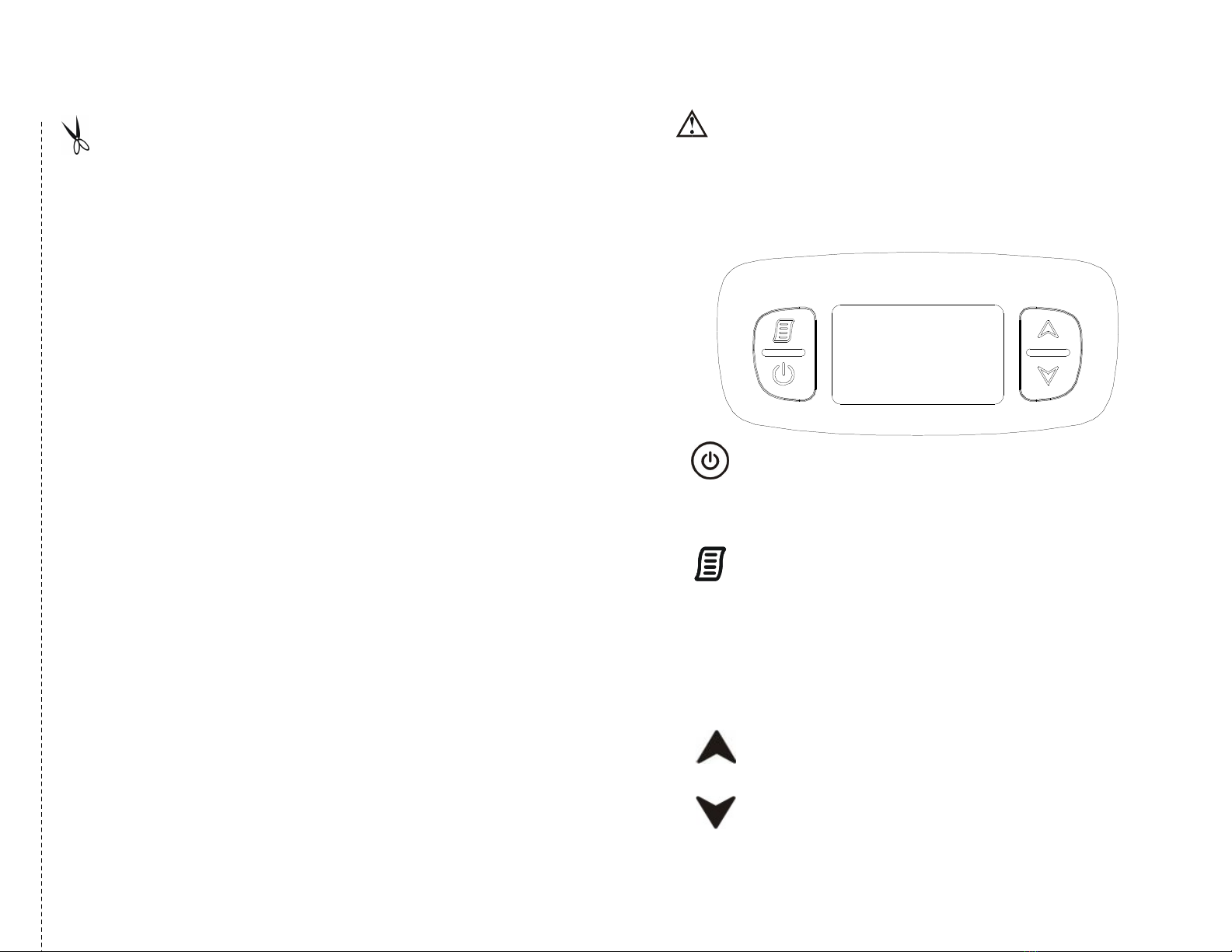
selection o pressing
"MENU"
is
[Ramp XX MIN]
. When the
"MENU"
setting is in
[Ramp
XX MIN]
mode, press
"UP"
or
"DO N"
button to set the pre erred ramp time and press
"MENU"
or con irmation. There are 10 adjustable levels, 0, 5, 10, 15, 20, 25, 30, 35, 40 and
45 minutes.
(2) Ramp Starting Pressure (only CPAP mode)
Press
"MENU"
button to select
[Ramp P XX.X]
menu, press
"UP"
or
"DO N"
button to
set the pre erred ramp starting pressure and press
"MENU"
or con irmation. The ramp
starting pressure can be changed rom 3 cmH2O to “Therapy Pressure – 1” cmH2O. For
example, i your therapy pressure is 10 cmH2O, the maximum ramp starting pressure you can
select is 9 cmH2O.
(3) Therapy Pressure (only CPAP mode)
Press
"MENU"
button to select
[P XX.XcmH
2
O]
menu, you can view the current pressure
setting displayed in cmH2O unit. Therapy pressure is adjustable only by the provider, a
respiratory therapist or physician.
NOTE: The therapy pressure is to only be prescribed by a physician.
(4) Initial Pressure (only APAP mode)
Press
"MENU"
button to select
[Init. XX.XcmH
2
O]
menu, you can view the current
pressure setting displayed in cmH2O unit. Initial pressure is adjustable only by the provider, a
respiratory therapist or physician.
NOTE: The initial pressure is to only be prescribed by a physician.
(5) Maximum Pressure (only APAP mode)
Press
"MENU"
button to select
[Max. XX.XcmH
2
O]
menu, you can view the current
pressure setting displayed in cmH2O unit. Maximum pressure is adjustable only by the provider,
a respiratory therapist or physician.
NOTE: The maximum pressure is to only be prescribed by a physician.
(6) Minimum Pressure (only APAP mode)
Press
"MENU"
button to select
[Min. XX.XcmH
2
O]
menu, you can view the current
pressure setting displayed in cmH2O unit. Minimum pressure is adjustable only by the provider,
a respiratory therapist or physician.
NOTE: The minimum pressure is to only be prescribed by a physician.
8
CPAP Model No.: 9S-005720
Additional instruction for Physician and Technician
(Do not distribute to patients)
1. To Select CPAP or APAP Mode
1. Press
"MENU"
to select
[Mode CPAP]
menu while in the standby screen.
2. Hold the
"UP"
and
"DO N"
button, and then simultaneously press the
"MENU"
button
or one second. Meanwhile, the LCD screen
[Mode CPAP]
should start blinking to
allow you to switch the mode rom CPAP to APAP.
3. Press
"UP"
or
"DO N"
button to select CPAP or APAP mode.
4. A ter selecting the mode, press
"MENU"
to con irm.
5. Press
“START/STANDBY”
button to go back to standby screen or leave the device to
automatically go back to standby screen 5 seconds later.
2. To Set the Pressure
6. Press
"MENU"
to select
[P XX.XcmH
2
O]
menu while in the standby screen in CPAP
mode.
7. Hold the
"UP"
and
"DO N"
button, and then simultaneously press the
"MENU"
button
or one second. Meanwhile, the LCD screen
[P XX.XcmH
2
O]
should start blinking to
allow you to adjust the therapy pressure rom 4 to 20 cm H2O.
8. Press
"UP"
or
"DO N"
button to increase or decrease the pressure setting. The
increment or decrement o pressure setting is 0.5 cm H2O.
9. A ter selecting the prescribed pressure, press
"MENU"
to con irm.
10. Press
“START/STANDBY”
button to go back to standby screen or leave the device
to automatically go back to standby screen 5 seconds later.
11. In APAP mode, ollow same instructions to set the initial pressure (Pinit), maximum
pressure (Pmax), and minimum pressure (Pmin) .
NOTE–I you try to set an maximum pressure lower than Pinit and Pmin , Pinit and Pmin will
automatically to be set lower than Pmax.
Cut this page along the dotted lines as indicated!!

FROM NORMAL WEAR OR FAILURE TO ADHERE TO THE ENCLOSED INSTRUCTIONS. IN
ADDITION, THE FOREGOING WARRANTY SHALL NOT APPLY TO SERIAL NUMBERED
PRODUCTS IF THE SERIAL NUMBER HAS BEEN REMOVED OR DEFACED; PRODUCTS
SUBJECTED TO NEGLIGENCE, ACCIDENT, IMPROPER OPERATION, MAINTANENCE OR
STORAGE; OR PRODUCTS MODIFIED WITHOUT PMI’S EXPRESS WRITTEN CONSENT
(INCLUDING, BUT NOT LIMITED TO MODIFICATION THROUGH THE USE OF UNAUTHORIZED
PARTS OR ATTACHMENTS, PRODUCTS DAMAGED BY REASON OF REPAIRS MADE TO ANY
COMPONENT WITHOUT SPECIFIC CONSENT OF PMI; PRODUCTS DAMAGED BY
CIRCUMSTANCES BEYOND PMI’S CONTROL; PRODUCTS REPAIRED BY ANYONE OTHER THAN
AN AUTHORIZED PMI DEALERS). SUCH EVALUATION SHALL BE SOLELY DETERMINED BY
PMI.
THE FOREGOING WARRANTY IS EXCLUSIVE AND IN LIEU OF ALL OTHER EXPRESS
WARRANTIES, IF ANY, INCLUDING THE IMPLIED WARRANTIES OF MERCHANTABILITY AND
FITNESS FOR A PARTICULR PURPOSE, AND SHALL NOT EXTEND BEYONG THE DURATION OF
THE EXPRESS WARRANTY PROVIDED HEREIN AND THE REMEDY FOR VIOLATIONS OF ANY
IMPLIED WARRANTY SHALL BE LIMITED TO REPAIR OR REPLACEMENT OF THE DEFECTIVE
PRODUCT PURSUANT TO THE TERMS CONTAINED HEREIN. PMI SHALL NOT BE LIABLE FOR
ANY CONSEQUENTIAL OR INCIDENTAL DAMAGES WHATSOEVER.
THIS WARRANTY SHALL BE EXTENDED TO COMPLY WITH STATE/PROVINCIAL LAWS AND
REQUIREMENTS.
ALL PRODUCTS LEAVE OUR WAREHOUSEIN BRAND NEW CONDITION. IT IS THE CUSTOMER’S
RESPONSIBILITY TO EXAMINE ALL SHIPMENTS FOR DAMAGE IMMEDIATELY UPON ARRIVAL.
COUNT THE PACKAGES AND SIGN FOR SAFE DELIVERY. SIGN ONLY FOR WHAT YOU RECEIVE.
IF MERCHANDISE IS DAMAGED CALL CARRIER AND SECURE DAMAGE INSPECTION REPORT
YOU HAVE 15 DAYS TO SECURE DAMAGE REPORTS OTHERWISE YOU MAY LOSE YOUR
PRIVILEGE OF FILLING A CLAIM FOR LOSS OR DAMAGE.
(7) Total Meter
Press
"MENU"
button to select
[TM XXXX.X hr]
menu, the total compliance meter records
the total number o hours that the device has been active. The meter should only be re-set by
the provider, a respiratory therapist or by a physician.
(8) Compliance Meter
Press
"MENU"
button to select
[CM XXXX.X hr]
menu, the compliance meter records the
total therapy hours or the device. The compliance meter should be re-set only by the provider,
a respiratory therapist or by a physician.
(9) Alarm
Press
"MENU"
button to select
[Alarm on/off]
menu, press
"UP"
or
"DO N"
button to set
the alarm on or o . When alarm is turned on, the audible alarm will activate with warning
messages showed on the LCD display. Set alarm o or mute the audible alarm.
(10) Clock Alarm
Press
"MENU"
button to select
[Clock Alarm on/off]
menu, press
"UP"
or
"DO N"
button to set the clock alarm on or o . When clock alarm is set on, the display will show the
time on the le t side. Press
"UP"
or
"DO N"
button to set the time to wake you up. Once the
clock alarm is activated, press the start/standby button to mute the audible alarm.
(11) Clock
Press
"MENU"
button to select
[Clock XX:XX]
menu, press
"UP"
or
"DO N"
button to set
the current time.
(12) Turn off the Device
Remove the power cord from the electrical outlet, and disconnect power cord from the power
socket on the back of device.
NOTE: Once the setting is confirmed, press “MENU”
button. Otherwise, the device will
automatically go back to standby without saving the modification if no action is
taken in 5 seconds.
(13) Event Indication
While the device is on standby mode, press
UP"
and
"DO N"
button at the same time to see
the latest data o Apnea Index (AI), Hypopnea Index (HI), Snoring Index (SI) and Flow
Limitation Index (FI) on the display. Press
"MENU"
button to show each index in sequence.
To go back to standby mode, press
"START/STANDBY"
button.
NOTE: Once the device is re-started, all the indexes will be re-calculated. Index data can
only be viewed by provider, respiratory therapists or physicians by using
Zzz-WARE Compliance &Efficacy Software.
9

4.3 Flowchart of Menu settings
Enter the user's menu mode by pressing the “
MENU
” button.
In each setting, when the pre erred value has been selected, press
"MENU"
or con irmation and
press
"MENU"
again to enter next selection.
NOTE: For physicians, please re er to a separated “Physician’s Additional Instruction” page.
10
Ramp
(Ramp Time)
< 0 ~ 45 > min
P
(Therapy Pressure)
< 4.0 ~ 20.0 > cmH2O
TM
(Total Meter)
< xxxx.x > hr
Ramp P
(Ramp Starting Pressure)
< 3.0 ~ 19.0 > cmH2O
CM
(Compliance Meter)
< xxxx.x > hr
Alarm
< on/o >
Clock Alarm
< on/o >
Clock
< hh:mm >
CPAP
CPAP
Mode
Int. P
(Initial Pressure)
< 3.0 ~ 19.0 > cmH2O
Max. P
(Maximum Pressure)
< 5.0 ~ 20.0 > cmH2O
APAP
A
PAP
Mode
Min. P
(Minimum Pressure)
< 4.0 ~ 19.0 > cmH2O
Alarm <On>
< hh:mm >
Clock Alarm <On>
< hh:mm >
18
LIMITED WARRANTY
PMI WARRANTS THIS PRODUCT TO BE FREE FROM DEFECTS IN MATERIALS AND
WORKMANSHIP.
PLEASE NOTE: THE WARRANTY BELOW HAS BEEN DRAFTED TO COMPLY WITH FEDERAL LAW
APPLICABLE TO PRODUCTS MANUFACTURED AFTER JULY 4, 1999.
THIS WARRANTY IS EXTENDED ONLY TO ORIGINAL PURCHASER/USER OF OUR PRODUCTS.
PMI WARRANTS ITS PRODUCTS TO THE ORIGINAL PURCHASER TO BE FREE FROM DEFECTS
IN MATERIAL AND WORKMANSHIP FOR TWO YEARS. IF WITHIN SUCH WARRANTY PERIOD ANY
SUCH PRODUCT SHALL BE PROVEN TO BE DEFECTIVE, SUCH PRODUCT SHALL BE REPAIRED
OR REPLACED, AT PMI’S OPTION. THIS WARRENTY DOES NTO INCLUDE ANY LABOR OR
SHIPPING CHARGES INCURRED IN REPLACEMENT PART INSTALLATION OR REPAIR OF ANY
SUCH PRODUCT. PMI’S SOLE OBLIGATION AND YOUR EXCLUSIVE REMEDY UNDER THIS
WARRANTY SHALL BE LIMITED TO SUCH REPAIR AND/OR REPLACEMENT. FOR WARRANTY
SERVICE, PLEASE CONTACT THE DEALER FROM WHOM YOU PURCHASED YOU PMI PRODUCT.
IN THE EVENT YOU DO NOT RECEIVE SATISFACTORY WARRANTY SERVICE, PLEASE WRITE
DIRECTLY TO PMI AT THE ADDRESS ON THE BACK PAGE. PROVIDE DEALER’S NAME,
ADDRESS, MODEL NUMBER, DATE OF PURCHASE, INDICATE NATURE OF THE DEFECT AND, IF
THE PRODUCT IS SEARIALIZED, INDICATE THE SERIAL NUMBER.
PMI WILL USE A RETURN AUTHORIZATION. THE DEFECTIVE UNIT OR PARTS MUST BE
RETURNED FOR WARRANTY INSPECTION USING THE SERIAL NUMBER, WHEN APPLICABLE,
AS INDENTIFICATION WITHIN 30 DAYS OF RETURN AUTHORIZATION DATE. DO NOT RETURN
PRODUCTS TO PMI WITHOUT PRIOR CONSENT. C.O.D. SHIPMENTS WILL BE REFUSED:
PLEASE REPAY SHIPPING CHARGES.
LIMITATIONS AND EXCLUSIONS: THE WARRANTY SHALL NOT APPLY TO PROBLEMS ARISING

compliance level above, the device should be observed to veri y normal operation. I abnormal per ormance is
observed, additional measures may be necessary, such as reorienting or relocating the device.
d Over the requency range 150 kHz to 80 MHz, ield strengths should be less than 3 V/m.
17
Recommended separation distances between portable and mobile RF
communications equipment and this device
This device is intended or use in an electromagnetic environment in which radiated RF disturbances
are controlled. The customer or the user o this device can help prevent electromagnetic inter erence
by maintaining a minimum distance between portable and mobile RF communications equipment (transmitters) and
this device as recommended below, according to the maximum output power o the communications equipment
Separation distance according to frequency of transmitter m Rated maximum
output power
of transmitter
W
150 kHz to 80
MHz
Pd 2.1=
80 MHz to 800
MHz
Pd 2.1=
800 MHz to 2,5 GHz
Pd 3.2=
0.01 0.12 0.12 0.23
0.1 0.38 0.38 0.73
1 1.2 1.2 2.3
10 3.8 3.8 7.3
100 12 12 23
For transmitters rated at a maximum output power not listed above, the recommended separation distance
d
in meters
(m) can be estimated using the equation applicable to the requency o the transmitter, where P is the maximum output
power rating o the transmitter in watts (W) according to the transmitter manu acturer.
Note 1: At 80 MHz and 800 MHz, the separation distance or the higher requency range applies.
Note 2: These guidelines may not apply in all situations. Electromagnetic propagation is a ected by absorption and
re lection rom structures, objects, and people.
5. Adding a Humidifier
Probasics Zzz-PAP AUTO CPAP device can be used
with Zzz-PAP integrated Heated Humidi ier
(9S-006500) which is available rom the home
care provider. The heated humidi ier may reduce
nasal dryness and irritation by providing
adequate moisture. Please re er to the Probasics
Zzz-PAP heated humidi ier (9S-006500)
instruction manual or complete setup
in ormation
NOTE: When the Probasics Zzz-PAP AUTO CPAP device is used with the heated humidifier,
its power supply is from the power socket outlet of the heated humidifier. Do not
connect the power cord to CPAP device and plug into main electrical outlet.
6. Using the miniSD Card to Collect Data
I physicians need to review the usage data, they may ask you to use the miniSD card to copy data
rom the device, and to return the card to them. Data that is copied to the miniSD Card is still stored
and available on the device.
1. Insert the miniSD Card when the device is in standby mode.
2. Data copying starts automatically when the miniSD Card is inserted into the slot.
3. The
[Card]
message is displayed on the LCD while data is being copied.
4. The
[OK Card ]
message is displayed on the LCD when copying has inished.
5. Remove the miniSD Card and bring/mail it to the Provider, Respiratory Therapist, Sleep Lab
Clinician or Physician as requested by your provider.
6. The miniSD Card should be stored in the plastic card case when not in use. The miniSD card does
not need to be uninstalled or the device to work properly.
CAUTION:
Do not remove the miniSD card until
[OK Card ]
message is displayed on the
LCD, or data copied to the card may be corrupted or missing.
7. Cleaning & Maintenance
7.1 Device
The device should be checked and dusted regularly (at least every 30 days). Wipe with a damp
cloth and a mild detergent and keep it ree rom dust. I other detergent is used, choose one
that will have no chemical e ects on the sur ace o the plastic case. All parts should be
air-dried thoroughly be ore use.
ARNING:
Don’t try to open this device. Repairs and internal servicing should only
per ormed by an authorized service agent. Don’t drop any oreign o
bject into the
air tube or air outlet.
11

7.2 Tubing and Mask
The tubing and mask should be checked and cleaned regularly. Please re er to the cleaning
instruction packaged with the accessories.
1. Disconnect the air tubing rom the air outlet o the device.
2. Remove the air tubing and headgear straps rom the mask.
3. Wash the mask and tubing according to the instructions supplied by your provider.
4. Be ore next use, assemble the mask and headgear according to the mask user
instructions.
5. All items o the mask and air tubing are subject to normal wear and tear and periodically
will need to be replaced. Contact your provider or replacement tubes, mask and
headgear.
CAUTION:
Do not use blench, chlorine-, alcohol-, or aromatic-based (including all
scented oils), moisturizing or antibacterial soaps to clean the cushion,
mask, air tubing. These solutions may cause hardening and reduce the
li e o the product.
CAUTION:
Do not wash or dry the mask or air tubing at a temperature above 70°C
(160°F)
ARNING:
Do not use any cleaner containing ragrance or conditioners as they will
leave a residue.
ARNING:
The mask must not be re-
used by another person. This is to avoid the risk
o cross-in ection.
7.3 Air Filter
The air ilter should be cleaned at least once every two weeks or more o ten i this device is
operated in a dusty environment and replaced with a new one every six months.
CAUTION:
Dirty air ilter may cause high operating temperatures that a ect device
per ormance. Ensure the air ilter is cleaned and itted at all times.
1. Remove the dirty ilter rom the enclosure on the rear
o the
device.
2.
Wash the ilter in warm water with a mild detergent, and rinse
with water. Allow the ilter to air dry completely be ore
reinstalling. Do not use a ilter that is not completely dry. I the
ilter is torn, replace it.
3. Reinstall the ilter.
NOTE: Please follow national requirements to dispose the unit properly.
12
8. Troubleshooting
16
Guidance and Manufacturer’s Declaration- Electromagnetic Immunity:
This device is intended or use in the electromagnetic environment speci ied below. The user o this device should make
sure it is used in such an environment.
Immunity Test IEC60601 test
level
Compliance Electromagnetic Environment-Guidance
Conducted RF
IEC 61000-4-6
Radiated RF
IEC 61000-4-3
3Vrms150 kHz to
80 MHz outside
ISM bandsa
3 V/m 80 MHz to
2.5 GHz
3Vrms
3V/m
Portable and mobile RF communications equipment
should be used no closer to any part o this device,
including cables, than there commended separation
distance calculated rom the equation applicable to
the requency o the transmitter.
Recommended separation distance
Pd 2.1= 150kHz to 80MHz
Pd 3.2=80 MHz to 2.5G MHz
Where P is the maximum output power rating o the
transmit
ter in watts (W) according to the transmitter
manu acturer and d is the recommended separation
distance in meters (m).b
Field strengths rom ixed RF transmitters, as
determined by an electromagnetic site survey c,
should be less than the compliance level in each
requency ranged.
Inter erence may occur in the vicinity o equipment
marked with the ollowing symbol:
NOTE 1 At 80 MHz and 800 MHz, the higher requency range applies.
NOTE 2 These guidelines may not apply in all situations. Electromagnetic propagation is a ected by absorption and
re lection rom structures, objects and people.
a The ISM (industrial, scienti ic and medical) bands between 150 kHz and 80 MHz are 6,765 MHz to 6,795 MHz;13,553
MHz to 13,567 MHz; 26,957 MHz to 27,283 MHz; and 40,66 MHz to 40,70 MHz.
b The compliance levels in the ISM requency bands between 150 kHz and 80 MHz and in the requency range 80 MHz
to 2,5 GHz are intended to decrease the likelihood that mobile/portable communications equipment could cause
inter erence i it is inadvertently brought into patient areas. For this reason, an additional actor o 10/3 is used in
calculating the recommended separation distance or transmitters in these requency ranges.
c Field strengths rom ixed transmitters, such as ba
se stations or radio (cellular/cordless) telephones and land mobile
radios, amateur radio, AM and FM radio broadcast and TV broadcast cannot be predicted theoretically with accuracy. To
assess the electromagnetic environment due to ixed RF transmitters, an electromagnetic site survey should be
considered. I the measured ield strength in the location in which the device is used exceeds the applicable RF

15
Appendix A: EMC Information
Guidance and Manufacturer’s Declaration- Electromagnetic Emissions:
This device is intended or use in the electromagnetic environment speci ied below. The user o this device should make
sure it is used in such an environment.
Emissions Test Compliance Electromagnetic Environment-Guidance
Harmonic emissions
IEC61000-3-2
Class A
Voltage luctua
tions /
Flicker emissions
IEC61000-3-3
Complies
The device is suitable or use in all establishments, including domestic
establishments and those directly connected to the public low-
voltage power
supply network.
Guidance and Manufacturer’s Declaration- Electromagnetic Immunity:
This device is intended or use in the electromagnetic environment speci ied below. The user
o this device should make sure it is used in such an environment.
Immunity Test IEC60601 test
level
Compliance Electromagnetic Environment-Guidance
Electrostatic
Discharge(ESD)
IEC61000-4-2
±6kV contact
±8kV air
±6kV contact
±8kV air
Floors should be wood, concrete or ceramic tile. I
loors are covered with synthetic material, the
relative humidity should be at least 30 %.
Electrical ast transient/
burst
IEC61000-4-4
±2kV or power
supply line
±1kV or input/out
line
±2kV or power
supply line
±1kV or input/out
line
Mains power quality should be that o atypical
commercial or hospital environment
Surge
IEC61000-4-5
± 1 kV line(s) to
line(s)
± 2 kV line(s) to
earth
± 1 kV line(s) to
line(s)
Mains power quality should be that o atypical
commercial or hospital environment.
Voltage dips, short
interruptions and voltage
variations on power
supply input lines
IEC61000-4-11
<5 % UT(>95 %
dip in UT) or 0,5
cycle
40 % UT(60 % dip
in UT) or 5 cycles
70 % UT(30 % dip
in UT) or 25 cycles
<5 % UT(>95 %
dip in UT) or 5 sec
<5 % UT(>95 %
dip in UT) or 0,5
cycle
40 % UT(60 % dip
in UT) or 5 cycles
70 % UT(30 % dip
in UT) or 25
cycles
<5 % UT(>95 %
dip in UT) or 5
sec
Mains power quality should be that o atypical
commercial or hospital environment. I the user o
this device requires continued operation during
power mains interruptions, it is recommended that
the device be powered rom an uninterruptible
power supply or a battery.
Power requency
(50/60Hz) magnetic
ield
IEC61000-4-8
3 A/m 3 A/m Power requency magnetic ields should be at levels
characteristic o atypical location in a typical
commercial or hospital environment.
NOTE: UT is the a.c. mains voltage prior to the application o the test level
Error 001
Error 002
Error 003
Error 004
Warn 001
Warn 002
Warn 003
Warn 004
Warn 005
The table below lists troubleshooting solutions or the problems that may happen. I the problem
persists, contact your equipment provider.
Prob l e m Pos s i b l e C a u s e s S olut i o n s
No display
1.
The power cord is not connected
to the power socket.
2. LCD ailure or controlled PCB
ailure.
1. Ensure the power cord is connected.
2. Contact your equipment provider or repair.
Display code
incorrect
LCD ailure or controlled PCB
ailure.
Contact your equipment provider or repair.
Illuminant under
LCD is not on
LED ailure Contact your equipment provider or repair.
Buttons disable Button ailure Contact your equipment provider or repair.
Air delivered is slow
1. During ramp time.
2. Filter is too dirty.
3. Flow generator ailure.
1. Check the ramp time setting
2. Change or clean the ilter regularly.
3. Contact your equipment provider or repair.
Data can not be
copied to the
miniSD card
1. miniSD card is ull.
2. miniSD card is not inserted
correctly.
3. Data on the miniSD card is
corrupted.
1. Ensure the miniSD card has enough
capacity.
2.
Ensure the miniSD card is inserted into the
slot correctly.
3. Contact your provider to re- ormat the card
or replace it.
Error / Warning Messages show in LCD.
Message type De inition Message in LCD
Error or abnormal system settings
Error or low generator ailure
Error or abnormal timer setting or timer
ailure
Error:
Primary unction can’t
execute.
Error or low sensor ailure
Out o system memory
System memory is nearly ull
miniSD card module c
ommunication
ailure
Remove the miniSD card while data is
being processed
Warning:
miniSD card is ull
NOTE: When the warning message appears, contact your physician or equipment provider to download
the memory data and reset the meter.
13

9. Technical Specifications
It em S p e c if i c a t i ons
Power Supply Universal power supply, AC100-240V, 50/60 Hz, 0.5-0.3A
Pressure Range 4-20 cmH2O (adjustable in 0.5 cmH2O increments)
Initial Pressure 3-19 cmH2O (adjustable in 0.5 cmH2O increments)
Maximum Pressure 5-20 cmH2O (adjustable in 0.5 cmH2O increments)
Minimum Pressure 4-19 cmH2O (adjustable in 0.5 cmH2O increments)
Ramp Time 0-45 minutes (adjustable in 5-minute increments)
Ramp Starting Pressure 3-19 cmH2O (adjustable in 0.5 cmH2O increments)
Operating Altitude up to 8,000 t (2,438 m) when the pressure is set at 4-18 cmH2O but
limit to 5,000 t (1,524m) when the pressure is set at 18.5 - 20 cmH2O
Dimensions (W x D x H) 14.5 x 13.0 x 10.0 cm or 5.7” x 5.1” x 3.9”
Weight Approximately 800 g or 1.76 lb
Sound Level 30 dBA at 10 cmH2O, 1 meter distance
Temperature Operating: +5°C to +35°C (+41°F to +95°F)
Storage: -15(C to 50(C (+5°F to +122°F)
Shipping: -15(C to 70(C (+5°F to +158°F)
Environment Humidity
Operating: 15%RH to 95%RH non-condensing
Storage: 10%RH to 90%RH non-condensing
Shipping: 10%RH to 90%RH non-condensing
Classification:
Class II
Type BF, Applied Parts Nasal Mask
Not suitable for use in the presence of a flammable
anesthetic mixture
IPX0: Enclosed equipment without protection
against ingress of water
Continuous operation.
Note: the manufacturer reserves the right to modify the specification
without notice.
14
BF symbol, which indicated this product is accor
ding to the degree o protecting
against electric shock or type BF equipment.
Attention, should read the instructions.
Class II
Disposal o Electrical & Electronic Equipment (WEEE):
This product should be handed over to an applicable collection point or the recycling
o electrical and electronic equipment. For more detailed in ormation about the
recycling o this product, please contact your local city
o ice, household waste
disposal service or the retail store where you purchased this product.
Authorized representative in the European community
Manu acturer
10. NOTE, CAUTION, AND ARNING STATEMENTS
NOTE:
Indicate in ormation that you should pay special attention to.
CAUTION:
Indicate correct operating or maintenance procedures in order to prevent
damage to or destruction o the equipment or other property.
ARNING:
Calls attention to a potential danger that requires correct procedures or
practices in order to prevent personal injury.
This manual suits for next models
1
Table of contents
Popular Medical Equipment manuals by other brands

Essilor Instruments
Essilor Instruments Mr Blue 2.0 Sun and Sport Edition user manual

ASAHI
ASAHI REXEED A Series Instructions for use

GE
GE Transport Pro Service manual

Care of Sweden
Care of Sweden CuroCell AREA Zone Instructions for use

OPTIKON
OPTIKON PULSAR2 ESP Installation and operating manual

ZOLL
ZOLL M2 Operator's guide

CU Medical Systems
CU Medical Systems iPAD SP1 Operation & Maintenance Policy

Medela
Medela Clario Instructions for use

Xstrahl
Xstrahl 100 Operator's manual

Defibtech
Defibtech DDU-2000 Series operating guide

Boston Life Labs
Boston Life Labs PC-68A user manual

sidhil
sidhil BARIATRIC DYNAMIC User instructions