Installation & Service Instructions:
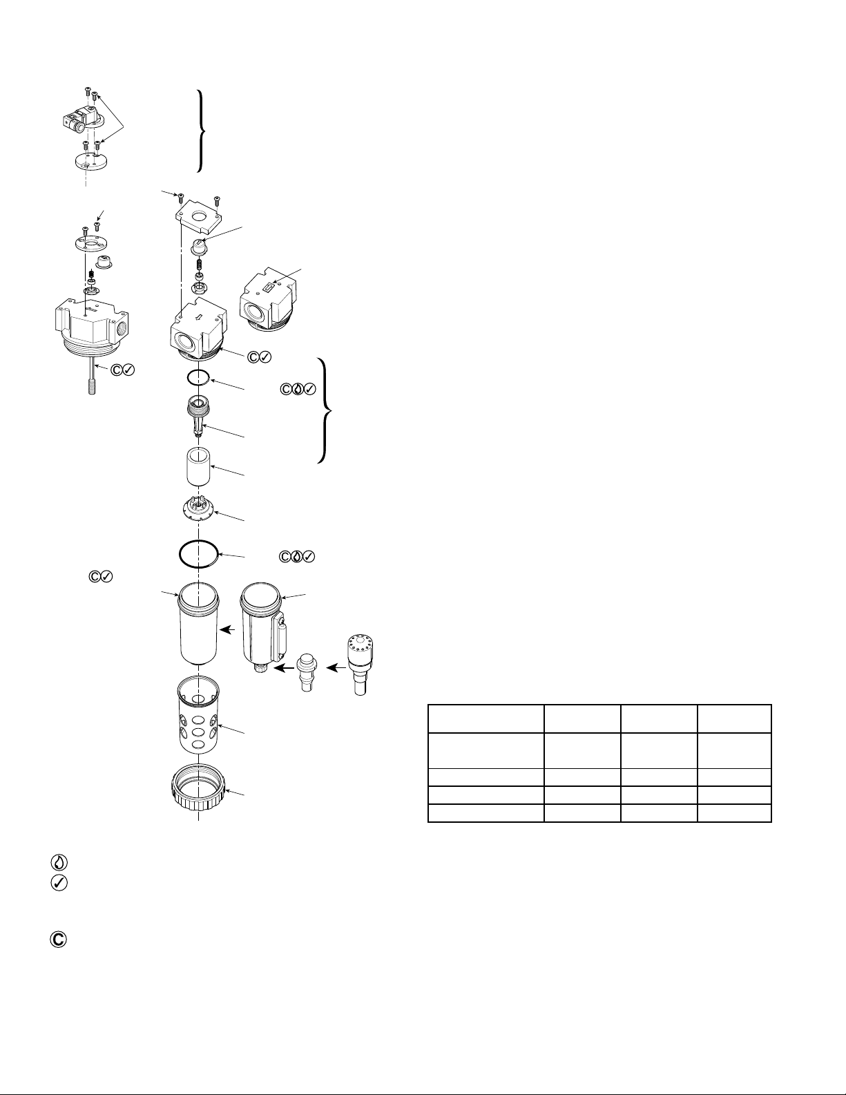
2C100F
1/8", 1/4" & 3/8" Economy
1/4", 3/8" & 1/2" Compact
3/8", 1/2" & 3/4" Standard
Coalescing Filter
ISSUED: September, 2006
Supersedes: November, 2003
Doc# 2C100, ECN# 060870, Rev. 9
Maximum Recommended Pressure Drop:
kPa PSIG bar
Coalescing Filter 70 10 0.7
With Polycarbonate Bowl
kPa PSIG bar
Operating Pressure Maximum 1000 150 10.3
Operating Temperature Maximum 52°C (125°F)
Operating Temperature Minimum 0°C (32°F)
With Metal Bowl
kPa PSIG bar
Operating Pressure Maximum 1700 250 17.0
Operating Temperature Maximum 80°C (175°F)
Operating Temperature Minimum 0°C (32°F)
05 / 15 Series With Metal Bowl and Auto Drain
kPa PSIG bar
Operating Pressure Maximum 1000 150 10.3
Operating Temperature Maximum 80°C (175°F)
Operating Temperature Minimum 0°C (32°F)
ANSI Symbols
Pneumatic Division
Richland, Michigan 49083
269-629-5000
Introduction
Follow these instructions when installing, operating, or servicing
the product.
Application Limits
These products are intended for use in general purpose
compressed air systems only.
Bowl guards are recommended for added protection of
polycarbonate bowls where chemical attack may occasionally
occur.
WARNING
To avoid polycarbonate bowl rupture that can cause personal injury
or property damage, do not exceed bowl pressure or temperature
ratings. Polycarbonate bowls have a 150 PSIG pressure rating and a
maximum temperature rating of 125°F.
WARNING
FAILURE OR IMPROPER SELECTION OR IMPROPER USE OF
THE PRODUCTS AND/OR SYSTEMS DESCRIBED HEREIN OR
RELATED ITEMS CAN CAUSE DEATH, PERSONAL INJURY AND
PROPERTY DAMAGE.
This document and other information from The Company, its subsidiaries
and authorized distributors provide product and/or system options for
further investigation by users having technical expertise. It is important
that you analyze all aspects of your application, including consequences of
any failure and review the information concerning the product or systems
in the current product catalog. Due to the variety of operating conditions
and applications for these products or systems, the user, through its own
analysis and testing, is solely responsible for making the final selection of
the products and systems and assuring that all performance, safety and
warning requirements of the application are met.
The products described herein, including without limitation, product
features, specifications, designs, availability and pricing, are subject
to change by The Company and its subsidiaries at any time without
notice.
EXTRA COPIES OF THESE INSTRUCTIONS ARE AVAILABLE FOR
INCLUSION IN EQUIPMENT / MAINTENANCE MANUALS THAT UTILIZE
THESE PRODUCTS. CONTACT YOUR LOCAL REPRESENTATIVE.
WARNING
To avoid unpredictable system behavior that can cause personal
injury and property damage:
• Disconnect electrical supply (when necessary) before installation,
servicing, or conversion.
• Disconnect air supply and depressurize all air lines connected
to this product before installation, servicing, or conversion.
• Operate within the manufacturer’s specified pressure,
temperature, and other conditions listed in these instructions.
• Medium must be moisture-free if ambient temperature is below
freezing.
• Service according to procedures listed in these instructions.
• Installation, service, and conversion of these products must be
performed by knowledgeable personnel who understand how
pneumatic products are to be applied.
• After installation, servicing, or conversion, air and electrical
supplies (when necessary) should be connected and the product
tested for proper function and leakage. If audible leakage is
present, or the product does not operate properly, do not put
into use.
• Warnings and specifications on the product should not be
covered by paint, etc. If masking is not possible, contact your
local representative for replacement labels.
CAUTION
Polycarbonate bowls, being transparent and tough, are ideal for use with
Filters and Lubricators. They are suitable for use in normal industrial
environments, but should not be located in areas where they could be
subjected to direct sunlight, an impact blow, nor temperatures outside
of the rated range. As with most plastics, some chemicals can cause
damage. Polycarbonate bowls should not be exposed to chlorinated
hydrocarbons, ketones, esters and certain alcohols. They should not be
used in air systems where compressors are lubricated with fire-resistant
fluids such as phosphate ester and diester types.
Metal bowls are recommended where ambient and/or media conditions
are not compatible with polycarbonate bowls. Metal bowls resist the
action of most such solvents, but should not be used where strong acids
or bases are present or in salt laden atmospheres. Consult the factory for
specific recommendations where these conditions exist.
TO CLEAN POLYCARBONATE BOWLS USE MILD SOAP AND WATER
ONLY! DO NOT use cleansing agents such as acetone, benzene, carbon
tetrachloride, gasoline, toluene, etc., which are damaging to this plastic.
Safety Guide
For more complete information on recommended application
guidelines, see the Safety Guide section of Pneumatic
Division catalogs or you can download the Pneumatic
Division Safety Guide at: www.parker.com/safety