First Sales IBW10-1 Quick start guide
First Sales, LLC
12630 US Highway 33 N
Churubusco, IN 46723
Phone (260) 693-1972 Fax (260) 693-0602
IBW-IMBW Instruction Manual 170605.docx
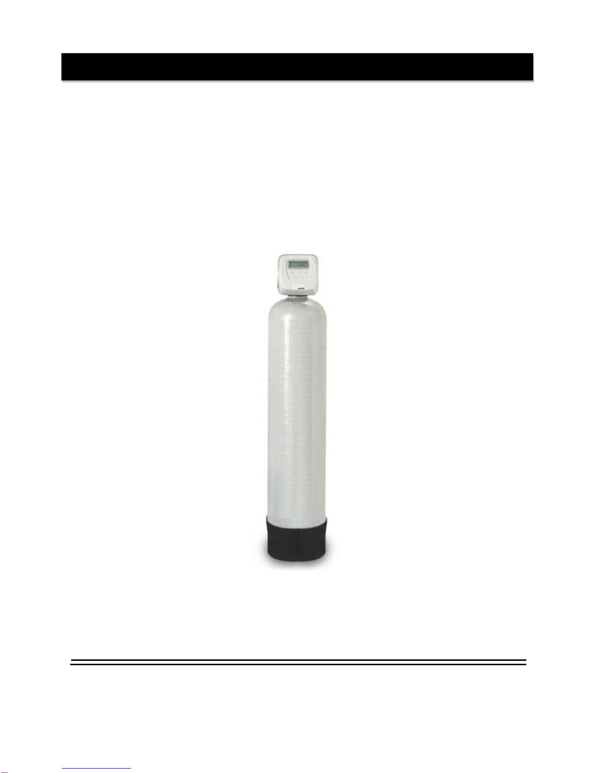
IBW & IMBW Series
Backwashing Filter System
Installation Instructions and Owner’s Manual

1
Pre-installation Instructions
Page 2
Media Types
Page 2
General Installation
Page 4
Bypass Valve
Page 5
Installation Instructions
Page 6
Operating Displays
Page 10
Maintenance
Page 11
Troubleshooting Guide
Page 13
Specifications
Page 16
Component Parts Breakdown
Page 17
Component Parts List
Page 18
Control Valve Breakdown
Page 19
Control Valve Parts List
Page 20
Installation Fittings
Page 21-23
Ten Year Limited Warranty
Page 24
Table of Contents

2
Description of the backwashing filter
The IBW/IMBW system includes a filtration tank (with gravel and distributor) and a backwashing control valve
with bypass. Filtration media for use with the IBW/ IMBW system is purchased separately and selected from
the following types:
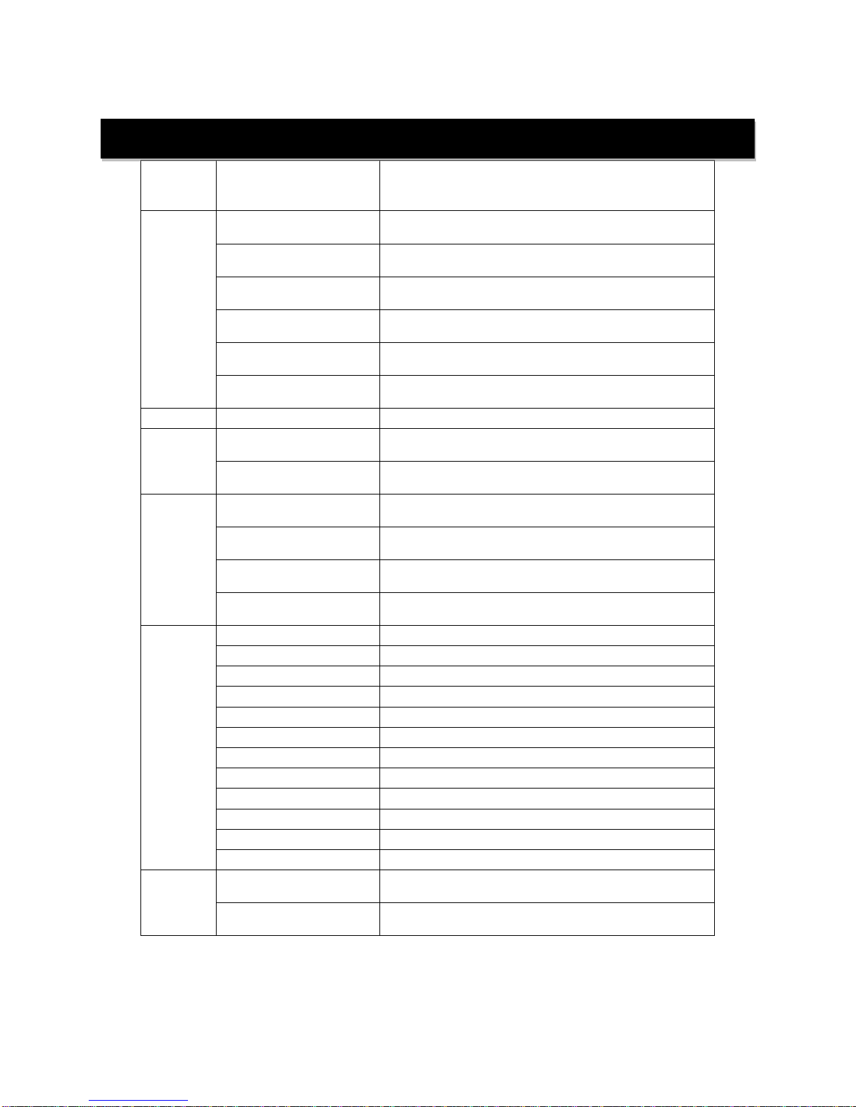
PART
MEDIA
VOLUME
PACKAGE
SHIP.
WT.
NUMBER
TYPE / APPLICATION
(CU. FT.)
(LBS.)
A10
ACTIVATED CARBON
TASTE & ODOR REDUCTION
1.00
BAG
29
A05P
0.50
PAIL
14
ACC10
CATALYTIC CARBON
CHLORAMINE REDUCTION
1.00
BAG
29
ACC05P
0.50
PAIL
14
B10
BIRM
REDUCTION OF IRON AND
MANGANESE
1.00
BAG
41
B05P
0.50
PAIL
20
C05P
CALCITE
SELF LIMITING ACID
NEUTRALIZER
0.50
PAIL
45
FA10
FILTER –AG
SUSPENDED SOLIDS
REDUCTION
1.00
BAG
24
FA05P
0.50
PAIL
12
N05
NEUTRALIZER
ACID NEUTRALIZER
0.50
PAIL
43
QFS05P
QUARTZ FILTER SAND
0.50
PAIL
51
(.45mm x .55mm)
SEDIMENT REDUCTION
Z05P
Zeolite
SUSPENDED SOLIDS &
SEDIMENT REDUCTION
0.50
PAIL
25
Successful Application
Any filter media may have specific limitations and/or requirements for successful application. A water sample
should be submitted to First Sales for analysis and recommendation by Customer Service.
Time of Backwash
Periodically the control valve will go through a backwash cycle. This cycle is factory preset to 12:00 A.M.
flushing the accumulated sediment and/or precipitant to the drain. After the backwashing process the unit is
now prepared for the next period of service.
Pre-installation Instructions

3
Water Supply
This filter will function properly when the water supply is furnished by a jet pump, submersible pump, variable
speed (constant pressure) pump or community water supply. As with all other filter systems, however, it is
imperative that the well pump provides enough flow rate for the filter to adequately backwash. In order to
ensure sufficient backwash flow rate the following pumping rate test should be performed prior to installing the
IBW/IMBW.
1. Make certain no water is being drawn in the house.
2. Open spigot nearest pressure tank.
3. When well pump starts, close spigot and measure time (in seconds) to refill pressure tank (well pump
turns back off). This is Cycle Time.
4. Using a container of known volume, draw water from pressure tank and measure how manygallons
until the pump turns back on again. This is Draw Down.
5. Calculate pumping rate bydividing draw down by cycle time and multiplying by 60.
Draw Down (gallons)
X
60
=
Pumping Rate (gallons per minute)
Cycle Time (seconds)
Example: Draw down is 8 gallons
Cycle time is 65 seconds
Location Considerations
The proper location to install the IBW/IMBW will ensure optimum filter performance and satisfactory water
quality. The following factors should be considered in selecting the location of this system.
1. The IBW/IMBW must be installed after the pressure tank (private well system only).
2. The system should be installed as close as possible (preferably within 15’) to an adequate floor or
laundry drain capable of handling the backwash cycle volume and flow rate (refer to unit
specifications). An air gap should be provided between the IBW/IMBW drain line and plumbing
drain.
3. All water conditioning equipment should be installed at least 10’ prior to the water heater. Water
temperatures exceeding 100°F can damage the internal components of the control valve and filter
tank. An expansion tank mayneed to be installed in the line to the water heater in order to allow for
thermal expansion and comply with local plumbing codes.
4. Water pressure must not exceed the range of 25 - 100 psi.
5. The system must not be subject to freezing temperatures.
6. The control valve requires 115/120 V, 60 Hz electricityfrom an outlet that is not wired to a switch.
7. Never install a cartridge type filter prior to the IBW/IMBW. Any cartridge or in-line filter (if desired)
may be installed after the IBW/IMBW system. This will prevent restricting the water flow and
pressure available for backwash.
8. Appliances requiring extended periods of continuous or high flow water use (i.e. geothermal heat
pumps,swimming pools, lawn irrigation, outside hose bibs, etc.) should bypass the filter.
8 gallons
X
60
=
7.4 gpm (gallons per minute)
65 seconds
Pre-installation Instructions (cont.)

4
GENERAL INSTALLATION & SERVICE WARNINGS
The water conditioner is not designed to support the weight of plumbing.
Do not use Vaseline, oils, other hydrocarbon lubricants or spray silicone anywhere. A silicone lubricant may be
used on black “O” Rings. This will allow ease of installation and decrease chance of rolling from the bypass and
tank connections. Avoid any type of lubricants, including silicone, on red or clear lip seals.
Do not use pipe dope or other sealants on threads. Teflon®tape must be used on the threads of the drain line
connection. Teflon®tape is not used on any connection where “O” Ring seals are used
The nuts and caps are designed to be unscrewed or tightened byhand or with the special plastic Service
Wrench, (CV3193, not included). If necessarypliers can be used to unscrew the nut or cap. Do not use a pipe
wrench to tighten nuts or caps. Do not place screwdriver in slots on caps and/or tap with a hammer.
NOTE: If the plumbing system is used as the ground leg of the electric supply, continuity should be maintained
byinstalling ground straps around any non-conductive plastic piping or bypass used in the installation.
Make sure the filter is not installed backwards. The filter will not function properly if installed backwards and filter
media may be forced into the water lines. Arrows molded into the valve body and red handles of the bypass
indicate the direction of flow.
Typical Installation
Water Heater
UntreatedWater
UntreatedWater for
geothermal heat pumps,
swimming pools, lawn
irrigation, hosebibs etc.
FIGURE 1: Typical Installation
FilteredHardWater
IBW/IMBW Filter
Softener
Brine Tank
PressureTank
Tank
TreatedWater
Grounding Strap
General Installation

5
The bypass valve is used to isolate the control valve from the plumbing system's water pressure in order to
perform control valve repairs or maintenance. The 1" full flow bypass valve incorporates four positions including
a diagnostic position that allows a service technician to have pressure to test a system while providing untreated
bypass water to the building. Be sure to install bypass valve onto main control valve, before beginning plumbing
or make provisions in the plumbing system for a bypass. The bypass body and rotors are glass filled Noryl®
and the nuts and caps are glass filled polypropylene. All seals are self-lubricating EPDM to help prevent valve
seizing after long periods of non-use. Internal "O" Rings can easily be replaced if service is required. The
bypass consists of two interchangeable plug valves that are operated independently by red arrow shaped
handles. The handles identify the direction of flow. The plug valves enable the bypass valve to operate in four
positions.
1. Normal Operation Position: The inlet and outlet handles point in the direction of flow
indicated by the engraved arrows on the control valve. Water flows through the control
valve for normal operation of a water softener or filter. During the regeneration cycle this
position provides regeneration water to the unit, while also providing untreated water to
the distribution system (Fig. 2).
2. Bypass Position: The inlet and outlet handles point to the center of the bypass. The
system is isolated from the water pressure in the plumbing system. Untreated water is
supplied to the building (Fig. 3).
3. Diagnostic Position: The inlet handle points toward the control valve and the outlet
handle points to the center of bypass valve. Untreated supply water is allowed to flow to
the system and to the building, while not allowing water to exit from the system to the
building (Fig. 4) .This allows the service technician to draw brine and perform other tests
without the test water going to the building.
NOTE: The system must be run through a rinse cycle before returning the bypass valve
to the normal position.
4. Shut Off Position: The inlet handle points to the center of the bypass valve and the outlet
handle points away from the control valve. The water is shut off to the building. The water
treatmentsystem will depressurize upon opening a tap in the building. A negative pressure
in the building combined with the softener being in regeneration could cause a siphoning
of brine into the building. If water is available on the outlet side of the softener it is an
indication of water bypassing the system (Fig. 5)
Figure 2 - Service
Figure 3 - Bypass
Figure 4 - Diagnostic
Figure 5 –Shut Off
Bypass Valve

6
STEP 1: Unpack filter unit, making sure to remove entire contents of the shipping container prior to
disposal.
STEP 2: With the filter unit in the upright position, remove the control valve from the mineral tank
being careful to not pull the distributor out of the gravel at the bottom of the tank.
STEP 3: Cover the top of the distributor tube with the included red cap and, using the included blue
media funnel, pour filter media(s) (purchased separately) into the mineral tank. If using
multiple filter media types, load in the order of heaviest (most dense) to lightest (least dense).
12” – 14” of space MUST be left empty at the top of the mineral tank to allow for media bed
expansion during backwash and to prevent filter media from being discharged through the
drain line.
STEP 4: Use a garden hose or bucket to fill the media tank with water.
IMPORTANT: Carbon, Filter Ag, Zeolite and Birm must be soaked for at least 2 hours
prior to submitting it to full flow rate to prevent loss of media to drain.
STEP 5: Clean mineral tank threads to remove any filter media. Remove red cap from distributor tube
and reinstall control valve by threading it securely onto the mineral tank. (O-ring seal: HAND
TIGHTEN ONLY!)
STEP 6: Shut off all water at main supply. On private well system, turn off power to pump and drain
pressure tank. Make certain pressure is relieved from complete system by opening nearest
faucet to drain system. SHUT OFF FUEL / ELECTRICAL SUPPLY TOWATER HEATER.
STEP 7: Plumb the water supply line to the unit's bypass valve inlet, located at the right rear as you
face the unit. There are a variety of installation fittings available. They are listed under
Installation Fitting Assemblies, pages 21-22. When assembling the installation fitting package
(inlet and outlet), connect the fitting to the plumbing system first and then attach the nut, split
ring, and "O" Ring. Heat from soldering or solvent cements may damage the nut, split ring, or
"O" Ring. Solder joints should be cool and solvent cements should be set before installing the
nut, split ring, and "O" Ring. Avoid getting solder flux, primer, and solvent cement on any part
of the "O" Rings, split rings, bypass valve, or control valve. If the building's electrical system is
grounded to the plumbing, install a copper grounding strap from the inlet to the outlet pipe.
Plumbing must be done in accordance with all applicable local codes. MAKE CERTAIN
WATER ENTERS THROUGH INLET AND DISCHARGES THROUGH OUTLET.
Installation Instructions
FIGURE 6: Top View of Control Valve with Bypass Installed
Outlet to Service
Inlet from Water
Supply
Retainer Clip
DLFC Retainer Clip
Brine Port Plug
Drain Line Flow Control
Elbow Assembly
(BarbedDLFC FittingNotShown)
7
STEP 8: Apply thread tape to DLFC Assembly. Remove drain line flow control (DLFC) retainer clip
(Figure 6, Page 6) and remove the DLFC assembly from the valve body, (Figure 6, Page 6).
Unscrew drain line elbow from DLFC. Apply thread tape to threads and re-attach the barbed
drain line elbow(not shown). Reinsert DLFC assemblyinto the valve body, making certain it is
FULLY inserted before replacing the retaining clip.
STEP 9: Install drain line (included). Use polyethylene tubing provided (NO VINLY TUBING) to run
drain line from control valve to floor drain, laundry drain or sump pit capable of handling the
backwash rate of the filter (refer to specifications and flow rate on page 16) or discard the
barbed fitting and use ¾” NPT fitting to connect a rigid pipe drain line (recommended). If
backwash flow rate is greater than 7 gpm or drain line length exceeds 15’, use ¾” rigid pipe for
drain line. There must be an air gap at the end of the drain line to prevent siphoning of waste
water. AVOID OVERHEAD DRAINS AND DRAIN LINE LONGER THAN 15’.
STEP 10: MAKE SURE THE BYPASS VALVE IS IN THE “BYPASS” POSITION (Figure3, Page 5)
NOTE: the INLET and OUTLET knobs turn clockwise to close the port to the softener and
counter-clockwise to open the port to the softener. Open the main supply valve or turn on
power to the pump on private well systems. Check for leaks andcorrect as needed
STEP 11: Pressurize the filter. Gradually turn the INLET side knob of the bypass valve counter-
clockwise ONLY ½ way (45 degrees) to the “Service” position (Figure 2, Page 5) allowing unit
to pressurize slowly. Check for leaks and correct as needed
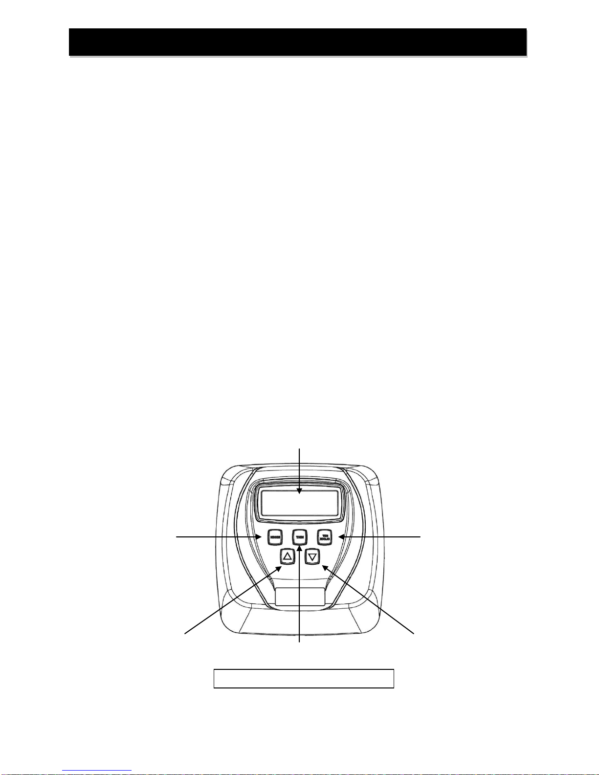
STEP 12: Program control valve. Plug the transformer of the control valve into an uninterrupted
electrical outlet (not wired to a switch) and use the buttons on the front of the control valve to
adjust the initial settings:
SET CLOCK
Button
NEXT
Button
Display Panel
REGEN
Button
FIGURE 7: Control Valve Front Panel
UP
Button
DOWN
Button
Installation Instructions (cont.)

8
A) SET THE TIME OF DAY
1. Press the “SET CLOCK” button
a. The upper left of the display will show “SET TIME”
b. The hour will flash
2. Press the “UP”or “DOWN”buttons (triangle pointing up or down) until the correct
combination of hour and “AM” or “P M” is reached to match the current time.
3. Press the “NEXT” button
a. The upper left of the display will show “SET TIME”
b. The minutes will flash
4. Press the “UP”or “DOWN”buttons until the minutes match the current time.
5. Press the “NEXT” button
a. The upper left of the display will show “TIME”
b. The current time of day will be shown on the right side of the display
c. Onlythe colon between the hour and minutes willbe flashing.
B) Enter Programming: Press “NEXT” and “UP”(triangle pointing up) buttons
simultaneously for 3 seconds.
1. Regeneration Days:
a. The upper left of the display will show “SET”
b. The lower left of the display will show “REGEN” above and “DAY” below.
c. A number will flash (default 3)
2. Using the “UP”or “DOWN”(triangle pointing up or down) buttons, set the number
of days (default 3, recommended) between regenerations.
3. Regeneration Time: Press the “NEXT” button
a. The upper left of the display will show “SET TIME”
b. The middle left of the display will show “REGEN”
c. The hour will flash
4. Regeneration Hour: Using the “UP”or “DOWN”buttons, set the combination of
hour of day and “AM” or “P M” (NOTE: letter spacing as shown on the display)
that the BACKWASH cycle of regeneration should occur. Make sure the filter is
not regenerating at the same time with any other water treatment equipment.
5. Press the “NEXT” button
a. The upper left of the display will show “SET TIME”
b. The middle left of the display will show “REGEN”
c. The minutes will flash
6. Regeneration Minutes: Using the “UP”or “DOWN”buttons, set the minutes
portion of the time when regeneration should occur.
Installation Instructions (cont.)

9
7. Exit Programming: Press the “NEXT” button
a. The upper left of the display will show “TIME”
b. The current time of day will be shown on the right side of the display
c. Onlythe colon between the hour and minutes will be flashing
d. and minutes will be flashing.
STEP 13: Initiate Manual Regeneration (Backwash Cycle): Press and hold the “REGEN” button 3
seconds or until the word “BACKWASH” appears in the lower right of the display and
“REGEN” appears at the middle left of the display. The drive motor will run briefly and count-
down timer will appear in the time-of-dayposition on the display.
STEP 14: Unplug the transformer from the electrical outlet to keep the IBW/IMBW in backwash for
an extended time to purge any air and remove media “fines” (very small particles of media).
STEP 15: Once the air is purged, gradually turn the INLET knob of the bypass valve counter-clockwise
until it is fully in “Service” position (Figure 2, Page 5). Then turn the OUTLET knob of the
bypass valve counter-clockwise until it is fully in the “Service” position (Figure 2, Page 5). and
leave the control valve in “Backwash” position for at least 10 minutes or until water
flowing from the drain line runs clear; whichever is longer.
STEP 16: Rinse Cycle: Plug the transformer into the electrical outlet. Press the “REGEN” button to
advance the control valve to the “RINSE” cycle. Another count-down timer will appear in the
time-of-day position, “RINSE” will be shown in the lower middle of the display and “REGEN”
appears in the middle left of the display.
STEP 17: Exit Manual Regeneration: Allow the rinse cycle to complete and the filter will return to
service mode automatically.
STEP 18: TURN ON FUEL / ELECTRICAL SUPPLY TOWATER HEATER.
RECOMMENDED: Retain the red distributor cap and blue media funnel for future replenishment of filter media.
NOTE: If the IBW/IMBW filter is loaded with any self-sacrificing media like Calcite or Neutralizer, mark
the media level on the side of the tank by shining a bright light through the tank to see its level.
Replenish the media in the mineral tank when the level drops by more than three inches.
Installation Instructions (cont.)

10
1. General Operation:
When the system is operating, one of the three displays maybe shown. Pressing next will alternate
between displays. One of the displays is always the current time of day. The second display shows
the current treated water flow rate through the system in Gallons Per Minute (gpm). NOTE: the
Gallons Per Minute display will always show 0.0 because there is no meter to detect flow in the
IBW/IMBW. The third displayshows the current days remaining before regeneration.
The user can scroll between the displays as desired.
If the system has called for a regeneration that will occur at the preset time of regeneration, the words
REGEN TODAY will appear on the display.
2. Regeneration Mode:
Typically a system is set to regenerate at a time of no water use. If
there is a demand for water when the system is regenerating,
untreated water will be delivered. When the system begins to
regenerate, the display will change to include information about the
step of the regeneration process and the time remaining for that
step to be completed. The system runs through the steps
automatically and will reset itself to provide treated water when the
regeneration has been completed.
3. Manual Regeneration:
Sometimes there is a need to regenerate before the control valve calls for it. This may be needed if a
period of heavy water use is anticipated or when experiencing excessive pressure drop.
To initiate a manual regeneration at the
preset delayed regeneration time, press
and release regen. The words “REGEN
TODAY” will flash on the display to
indicate that the system will regenerate at
the preset delayed regeneration time.
If you pressed the regen button in error,
pressing the button again will cancel the
command.
To initiate an immediate manual regeneration, press and hold the regen button for
three seconds. The system will begin to regenerate immediately. This command
cannot be cancelled.
4. Power Loss:
If the power goes out for less than two hours, the system will
automaticallyreset itself. If an extended power outage
occurs, the time of day will flash on and off which indicated
the time of day should be reset. The system will remember
all other settings.
Error Message: If the word “ERROR” and a number are
alternately flashing on the display, record the number and contract the dealer for help. This indicates
that the control valve was not able to function properly.
Operating Displays

11
1) If your unit contains activated carbon, you should replace the carbon and gravel underbed at least
every three years. Replacement may be required sooner if the taste and odor being removed begins to
reappear in the treated water or you experience increasing pressure drop that is not resolved by
increasing the frequencyof backwashing.
2) Filter Ag and Filter Sand will last indefinitely. It may be necessary to replace them if you experience
increasing pressure drop that is not resolved by increasing the frequencyof backwashing or if water
quality diminishes due to contaminant bleed through.
3) Neutralizer media or calcite must be replenished at least annually. Mark the side of the mineraltank at
installation so the drop in media levelmay be monitored by shining a bright light behind the mineral
tank. Add media if the level has dropped by more than three inches.
4) Birm should be replaced when iron reappears in the treated water and backwashing does not improve
the water quality.
TO REPLENISH OR REBED MEDIA:
1) Pressure must be relieved on the system by placing the Bypass Valve in the “Bypass” position (Figure
3, Page 5) and initiating a manual regeneration (section 3, page 10).
2) Unplug the Control Valve from the electrical outlet to prevent it from advancing automatically.
3) Disconnect the Control Valve from the Bypass Valve
4) Disconnect the Drain Line from the Control Valve
5) Unscrew Control Valve from Mineral Tank (IF REBEDDING ONLY! Remove the distributor).
6) Siphon water from Mineral Tank (IF REBEDDING ONLY! Remove existing media and gravel).
7) (IF REBEDDING ONLY! Rinse Mineral Tank and replace distributor, making certain that the
distributor basket sits in the center of the tank bottom.)
8) Cover the top of the distributor tube to prevent media entering the tube during filling. Using a funnel,
pour filter media(s) into the mineral tank. (IF REBEDDING ONLY! Begin loading the tank with the
gravel underbed. Filling the Mineral Tank 1/3 with water before loading gravel will cushion the
fall and ensure even distribution of the gravel and media. If using multiple filter media types,
load in the order of heaviest {most dense} to lightest {least dense}.) 12” – 14” of space MUST be
left empty at the top of the mineral tank to allow for media bed expansion during backwash and to
prevent filter media from being discharged through the drain line.
9) (IF REBEDDING ONLY! Use a garden hose or bucket to fill the media tank with water.)
10) Clean mineral tank threads to remove any filter media. Uncover distributor tube and reinstall control
valve by threading it securely onto the mineral tank. (O-ring seal; HAND TIGHTEN ONLY!)
Maintenance

12
11) Attach bypass valve (Figure 6, Page 6) to control valve body.
12) Reattach Drain Line to Control Valve (Figure 6, Page 6).
13) IMPORTANT! Activated Carbon, Filter Ag, Zeolite and Birm must be soaked for at least 2 hours
prior to submitting it to full flow rate to prevent loss of media to drain.
14) Gradually turn the INLET side knob of the bypass valve counter-clockwise ONLY ½ way (45 degrees)
to the “Service” position (Figure 2, Page 5) allowing unit to pressurize slowly. Check for leaks and
correct as needed Any air trapped in the media bed should begin purging to the drain and water
should begin flowing to the drain.
15) Once the air is purged, gradually turn the INLET knob of the bypass valve counter-clockwise until it is
fully in “Service” position (Figure 2, Page 5). Then turn the OUTLET knob of the bypass valve counter-
clockwise until it is fully in the “Service” position (Figure 2, Page 5). and leave the control valve in
“Backwash” position for at least 10 minutes or until water flowing from the drain line runs clear;
whichever is longer.
16) Plug the transformer into the electrical outlet. Press the “REGEN” button to advance the control valve
to the “RINSE” cycle. Another count-down timer will appear in the time-of-day position, “RINSE” will be
shown in the lower middle of the display and “REGEN” appears in the middle left of the display. Allow
the rinse cycle to complete and the filter will return to servicemode automatically.
Maintenance (cont.)

13
PROBLEM
CAUSES
SOLUTIONS
Excessive pressure drop
through filter
A) Filter not
backwashing
B) Filter not
backwashing
frequently enough
for water condition
C) Filter bed loaded
with sand
D) “Cementing” or
“Channeling”
E) Drain Line restricted
F) Top Screen Fouled
G) Control Valve
plugged with debris
1) Check if display is blank, see “Blank
Display” section of Page 14.
2) Check if display has an error
message, see “Error Code” section of
Page 15.
3) Verify drive motor is connected to
circuit board connector J1 (labeled
“MOTOR”) and is not faulty
4) Ensure uninterrupted power supply
5) Increase Backwash frequency
6) Verify sediment being removed is less
dense than the filter media and install
a “Spin-Down” type sediment filter
ahead of the IBW/IMBW to remove
well sand
7) Verify adequate pumping rate for
backwash
8) Probe media bed to check for
“Cementing”
9) Check drain line for restriction: frozen,
plugged, kinked, exceeds 15’,
overhead installation, flexible drain
line, drain line diameter too small
10) Clean top screen
11) Disassemble and clean control valve
Contaminant not being
properly removed
A) Leaking bypass
valve
B) Internal valve leak
C) Distributor tube not
seated properly in
control valve
D) Water usage flow
rate exceeds filter
specifications
1) Verify bypass valve is in service
position
2) Replace piston and seal assemblies
3) Verify distributor tube seated securely
in control valve body
4) Verify actual water usage flow rates
against system specifications
5) Increase length of backwash and rinse
cycles
Neutralizer media raises
pH too high
A) Filter is brand new
B) Wrong media used
1) Turn bypass valve veryslightlyto the
“Bypass” position allowing a small
amount of untreated water to bleed
into the treated water (only if iron < 0.3
ppm, otherwise staining will occur)
2) Rebed the unit with a less aggressive
media
Neutralizer media fails to
raise pH sufficiently
A) Water usage flow
rate is too high to
provide adequate
contact time
B) Media bed is
“Cemented” or
“Channeled”
1) Verify actual water usage flow rates
against system specifications
2) Verify adequate pumping rate for
backwash
3) Check drain line for restriction: frozen,
plugged, kinked, exceeds 15’,
overhead installation, flexible drain
line, drain line diameter too small
Birm Filter fails to remove
iron
A) pH too low
B) Dissolved oxygen
level too low
1) pH of untreated water must be 6.8 or
higher –adjust with proper equipment
such as soda ash injection system
2) Aerator maybe installed prior to the
Troubleshooting

14
filter
PROBLEM
CAUSES
SOLUTIONS
Loss of media
to drain
A) Air in system
B) Insufficient soak
time before first
backwash after
installing media
1) Ensure well system has proper air
elimination control
2) Check media level and adjust if
necessary
Media in service lines
A) Unit is installed
backwards
B) Distributor basket
is broken
C) Insufficient gravel
under bed
1) Re-plumb the water lines so that the
supplyside of the line is connected to
the inlet of the bypass and the service
side is connected to the outlet.
2) Replace distributor.
3) Add gravel to tank, manually
backwash
Howling or whistling noise
during regeneration
A) Inadequate drain
line diameter or
drain line restricted
1) Reconfigure or replace drain line
Continuous flow of water
to drain
A) Loss of electrical
power during
regeneration
B) Debris in control
valve
C) Internal leak in
control valve
1) Ensure electrical outlet is functioning
2) Disassemble and clean control valve
3) Replace seals and/or piston
Filter backwashes at
wrong time of day
A) Clock is not set
properly
B) Power outage
C) Incorrect control
valve programming
1) Reset the clock (page 8)
2) Verifycontrol valve programming
(page 8)
Displayis blank
A) Control valve circuit
board needs reset
B) Transformer is
unpowered,
unplugged or
defective
C) Defective circuit
board
1) Hold “NEXT” and “REGEN” buttons
for 3 seconds
2) Short leftmost 2 pins of connector J10
on control valve circuit board for 3
seconds
3) Verify transformer is plugged into an
electrical outlet that has power and
transformer cable (black, 4 pins) is
plugged into control valve connector
J4 (labeled “12VAC PWR”)
4) With transformer plugged into
electrical outlet, use a volt meter to
test the 2 outer pins (furthest left and
furthest right) of connector J4 on the
control valve circuit board. Should be
approximately 12 volts AC. Replace
transformer if defective.
5) Replacecircuit board if needed
Troubleshooting (cont.)

15
ERROR CODE:
CAUSES
SOLUTIONS
1001 –unable to
sense motor
movement
A) Drive motor not
inserted fully to
engage pinion or is
defective
B) Circuit board not
properly snapped
into drive bracket
C) Center reduction
gear reflector dirty
1) Re-insert motor, check for broken wires,
verify motor plugged into connector J1
(labeled “MOTOR”) on control valve circuit
board and reset control valve (hold “NEXT”
and “REGEN” buttons for 3 seconds)
2) Re-seat circuit board into drive bracket and
reset control valve
3) Clean reduction gear reflectors (page 19)
1002 –unexpected
motor stall
A) Obstruction in
control valve
B) Main drive gear too
tight
C) Improper voltage
delivered to circuit
board
1) Remove piston and seal assemblies for
inspection and repair or replacement and
reset control valve (hold “NEXT” and
“REGEN” buttons for 3 seconds)
2) Loosen main drive gear and reset control
valve
3) Verifyproper voltage is being suppliedto
circuit board (see Solution 4 under “Display
is Blank” section, page 14)
1003 –motor ran too
long, cannot find next
cycle position
A) Motor failure during
regeneration
B) Obstruction in
control valve
C) Drive bracket not
snapped in place
properly
1) Re-insert motor, check for broken wires,
verify motor plugged into connector J1
(labeled “MOTOR”) on control valve circuit
board and reset control valve (hold “NEXT”
and “REGEN” buttons for 3 seconds)
2) Remove piston and seal assemblies for
inspection and repair or replacement and
reset control valve
3) Re-seat drive bracket assembly and reset
control valve
1004 –motor ran too
long, timed out trying
to reach home
position
A) Drive bracket not
snapped in place
properly
B) Center reduction
gear reflector dirty
1) Re-seat drive bracket assembly and reset
control valve (hold “NEXT” and “REGEN”
buttons for 3 seconds)
2) Clean reduction gear reflectors (page 19)
1006–MAV/SEPS/
NHBP/AUX MAV
motor ran too
long,looking for park
position
A) Control valve not
programmed for
ALT oFF
B) Obstruction in
control valve
1) Enter cycle programming level and verify
second parameter is set to ALT oFF
2) Remove piston and seal assemblies for
inspection and repair or replacement and
reset control valve (hold “NEXT” and
“REGEN” buttons for 3 seconds)
1007–MAV/SEPS/
NHBP/AUX MAV
motor ran too short
looking for park
position
A) Control valve not
programmed for
ALT oFF
B) Obstruction in
control valve
1) Enter cycle programming level and verify
second parameter is set to ALT oFF
2) Remove piston and seal assemblies for
inspection and repair or replacement and
reset control valve (hold “NEXT” and
“REGEN” buttons for 3 seconds)
Troubleshooting (cont.)

16
Description
IBW10-1
IMBW10-1
IBW15-1
IMBW15-1
IBW20-1
IMBW20-1
IBW25-1
IMBW25-1
Filter Media Volume, cu. ft.
1.0
1.5
2.0
2.5
Gravel Underbed, lbs.
20
20
25
25
Operating Flow Rate, gpm
Continuous
@ 5 gpm/ft2of media surface area
3
3
4
5
Peak
@ 18 gpm/ft2of media surface area
10
10
14
17
Backwash
@ 10 gpm/ft2of media surface area
NOTE: some medias may require a
higher backwash rate
5.3
5.3
7.5
9
Service Pipe Size, in.
Standard
1
1
1
1
Tank Diameter x Height, in.
10 x 44
10 x 54
12 x 48
13 x 54
Minimum Space Required, in.
Width
12
12
13
14
Depth
18
18
18
18
Height
56
66
60
66
Approximate Ship Wt., lbs.
62
68
68
73
(Media Not Included)
SPECIFICATIONS

17
3
1
4
5
6
2
Component Parts Breakdown
18
*
Filter media sold seperately. Select appropriate media for water condition (page 2).
Ref #
Part Number
Description
1
IBW10 Vlv Assy L/BP
Control Valve, Cover, 5.3 GPM DLFC, less bypass
for models IBW10 & IBW15
IBW20 Vlv Assy L/BP
Control Valve, Cover, 7.5 GPM DLFC, less bypass
for model IBW20
IBW25 Vlv Assy L/BP
Control Valve, Cover, 9.0 GPM DLFC, less bypass
for model IBW25
IMBW10 Vlv Assy L/BP
Control Valve, Cover, 5.3 GPM DLFC, less bypass
for models IMBW10 & IMBW15
IMBW20 Vlv Assy L/BP
Control Valve, Cover, 7.5 GPM DLFC, less bypass
for model IMBW20
IMBW25 Vlv Assy L/BP
Control Valve, Cover, 9.0 GPM DLFC, less bypass
for model IMBW25
2
CD1203
Top Screen
3
D100S-48
Distributor Tube, 1" x 48"
for models IBW10, IBW20, IMBW10, & IMBW20
D100S-54
Distributor Tube, 1" x 54"
for model IBW15, IBW25, IMBW15, & IMBW25
4
MTP1044N
10 x 44 Mineral Tank, Nat, Base, 2.5" Top Opening
For model IBW10 & IMBW10
MTP1054N
10 x 54 Mineral Tank, Nat, Base, 2.5" Top Opening
For model IBW15 & IMBW15
MTP1248N
12 x 48 Mineral Tank, Nat, Base, 2.5" Top Opening
For model IBW20 & IMBW20
MTP1354N
13 x 54 Mineral Tank, Nat, Base, 2.5" Top Opening
For model IBW25 & IMBW25
5*
A10
Activated Carbon, 1.00 cu. ft. bag
A05P
Activated Carbon, 0.50 cu. ft. pail
ACC10
Catalytic Carbon, 1.00 cu. ft. bag
ACC05P
Catalytic Carbon, 0.50 cu. ft. pail
B10
Birm, 1.00 cu. ft. bag
B05P
Birm, 0.50 cu. ft. pail
C05P
Calcite, 0.50 cu. ft. pail
FA10
Filter Ag, 1.00 cu. ft. bag
FA05P
Filter Ag, 0.50 cu. ft. pail
N05
Neutralizer, 0.50 cu. ft. pail
Z05P
Zeolite, 0.50 cu. ft. pail
QFS05P
Quartz Filter Sand, 0.50 cu. ft. pail
6
QC20
1/4" x 1/8" Gravel, 20 lb Pail
for models IBW10, IBW15, IMBW10, & IMBW15
QC25
1/4" x 1/8" Gravel, 25 lb Pail
For models IBW20, IBW25, IMBW20, & IMBW25
Component Parts List

19
Control Valve Breakdown
This manual suits for next models
7
Table of contents
Other First Sales Water Filtration System manuals


Popular Water Filtration System manuals by other brands

IDEAL H2O
IDEAL H2O 100 GPD Setup and maintenance guide

Parker
Parker F55 Series Installation & service instructions

BRÖTJE
BRÖTJE ZLF 160 Assembly instructions

Culligan
Culligan Iron-Cleer owner's guide

Mitsubishi Electric
Mitsubishi Electric PAC-TS70TB installation manual

EasyPro
EasyPro EPU18N Instructions for Operation, Safety, Warranty


