Podium Pro Audio MX602 User manual

Podium Pro Audio
Audio at its highest level
http://www.podiumproaudio.com
© 2010
Podium Pro Audio
Model MX602
6 Channel 2 Bus Mixing Console
User’s Manual
INTRODUCTION 2
MX602 FEATURES 2
BEFORE YOU BEGIN 2
USING THIS MANUAL 2
ABOUT THE MX602 BLOCK DIAGRAM 2
MONO MIC / LINE INPUT CHANNELS (1 - 2) 3
STEREO INPUTS (3/4 – 5/6) 3
MAIN SECTION 3,8
INPUT / OUTPUT CONNECTIONS 3,9
MONO MIC / LINE CONNECTIONS AND CONTROLS 4
STEREO INPUT CONNECTIONS AND CONTROLS 5
MX602 BLOCK DIAGRAM 6-7
INSTALLATION 10
CONNECTOR WIRING 10
SPECIFICATIONS 11

INTRODUCTION
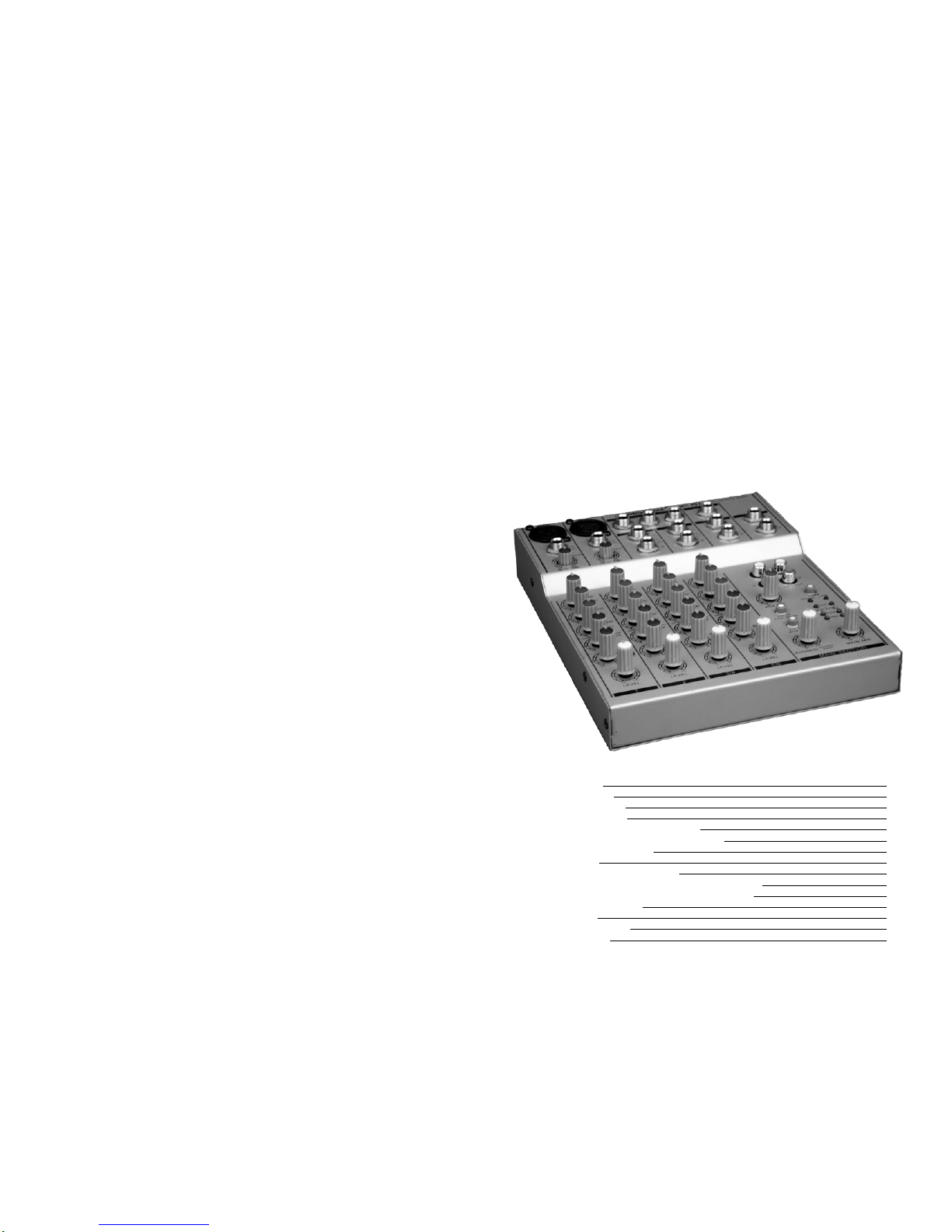
The Podium Pro Audio MX602 audio mixing console brings premium quality
audio processing circuitry into the compact desktop class of mixers. Carefully
designed signal routing, phantom microphone power, fully balanced design and
versatile effects loops allow this console to provide class leading performance
and flexibility. Used in accordance with the information provided in this manual,
this product will give years of trouble free use.
MX602 FEATURES
•Two studio grade “Invisible” ultra low noise microphone (MIC) preamps
•Two balanced line inputs
•Two balanced stereo inputs (four mono)
•Direct-coupled signal processing.
•Rugged steel construction provides superior noise shielding.
BEFORE YOU BEGIN
•Read and follow these instructions.
•Heed all warnings.
•Do not use where the mixer may get wet.
•Never defeat the AC polarizing or safety ground on the AC cord.
•Be certain all equipment is OFF before making or breaking
connections.
•Clean console only with a damp (not wet) cloth.
•Refer all service needs to qualified personnel. There are no user
serviceable components inside.
USING THIS MANUAL
A basic understanding of what a mixing console does is very important. On the
next page the console is filtered down to logical function “blocks”, and their use
is summarized. Following the summaries you will find detailed descriptions of
all controls and connections.
ABOUT THE MX602 BLOCK DIAGRAM
A block diagram is a simplified schematic which illustrates signal flow from
input to output and shows the numerous routing variations possible. It is highly
recommended that you make frequent use of the block diagram to get the most
out of your MX602 mixer. You will find the MX602 block diagram on pages 6
and 7. Throughout this manual, you will frequently see the opamp symbol. . .
h
This indicates that understanding the current topic will be much easier if you
review the block diagram.
2
SPECIFICATIONS
MICROPHONE INPUTS:
Frequency Response: (±2dB) <20Hz to 50kHz
Balanced XLR. PIN 1:ground, PIN 2:(+) PIN 3:(-)
Distortion (THD+N): 0.01% at +4dBu, 1kHz
Gain: Adjustable, +10dB to +60dB
Signal-to-Noise ratio: 114dB
Equivalent Input Noise: (20Hz to 20kHz)
Source impedance = 0Ω: -132dB
Source impedance = 150Ω: -129dB
Distortion: (THD+N) 0.005%/0.004% A-weighted
MONO LINE INPUTS:
Frequency Response: (±2dB) <20Hz to 50kHz
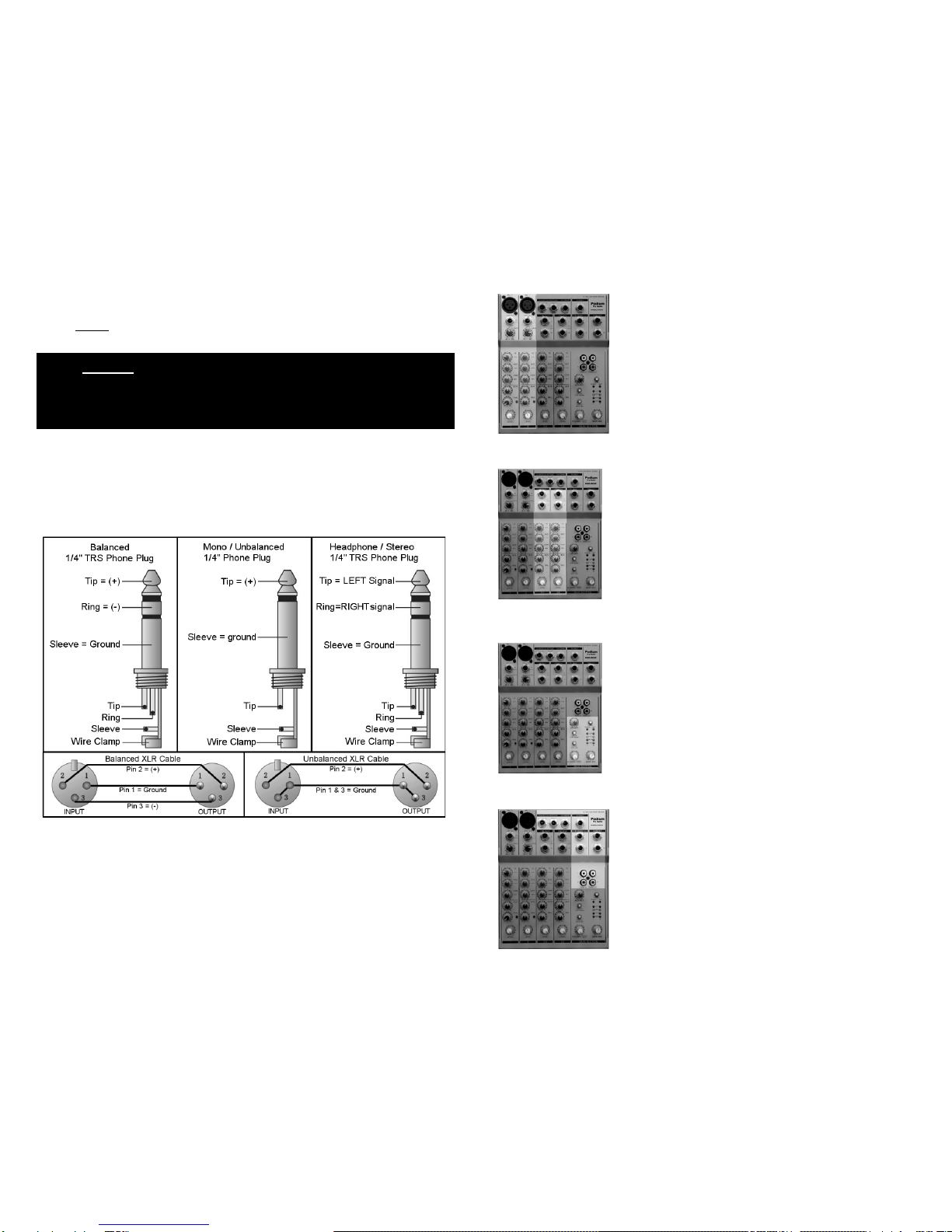
Balanced ¼” phone jack. TIP:(+) RING:(-)
SLEEVE:ground
Distortion (THD+N): 0.01% at +4dBu, 1kHz
Gain Range: +10dBu -40dBu
STEREO INPUTS:
Frequency Response: (±2dB) <20Hz to 50kHz
Balanced ¼” phone jacks. TIP:(+) RING:(-)
SLEEVE:ground
Distortion (THD+N): 0.01% at +4dBu, 1kHz
LOW: ± 15dB @ 80Hz, shelving, MID: ± 15dB @ 2.5kHz, HI: ± 15dB @ 12kHz,
shelving
ALL EQUALIZERS
AUX SENDS:
Output impedance: ≈120Ω
Unbalanced ¼” phone jacks. TIP:(+) SLEEVE:ground
Maximum output level: +22dBu
MAIN OUTPUTS:
Maximum output level: +22dBu
Unbalanced ¼” phone jack. TIP:(+) SLEEVE:ground
Signal to noise ratio: 112dB
Equivalent input noise: -90dBu (all channels open, unity gain)
CONTROL ROOM OUTPUTS:
Maximum output level: +22dBu
Unbalanced ¼” phone jacks. TIP:(+)
SLEEVE:ground
Signal to noise ratio: 112dB
Equivalent input noise: -90dBu (all channels open, unity gain)
POWER CONSUMPTION: 120VAC, 18W
DIMENSIONS:
Weight: 1.2kg (2-5/8lbs) With power supply: 1.9kg (2-1/4lbs)
H=50mm (2”) W=170mm (6-5/8”) D=215mm (8.5”)
11

INSTALLATION
•The MX602 is designed for indoor use. Never use in a location where the unit may get
wet.
•NEVER
CONNECTOR WIRING
defeat the safety ground provision of the IEC power cord.
You will need many cables to complete the installation. Many more will be required for signal
patching during sessions. Pre-fabricated cables may not always fit your needs and sometimes
onsite repairs are necessary. The following illustrations show the correct connector wiring.
10
MONO MIC / LINE INPUT CHANNELS (1 - 2) DETAILS ON PG 4
There are two identical MONO input channels located
on the left of the console. These channels are
organized vertically. At the top is an XLR microphone
(MIC) input jack. 48V “phantom” power is available for
condenser MICs. Next is a ¼” Tip Ring Sleeve (TRS)
line level (LINE) input phone jack. Each MONO channel
can be used as either a MIC or LINE input. The other
controls provide a wide variety of sound shaping, signal
routing, external processing and gain adjustments.
STEREO INPUTS (3/4 - 5/6) DETAILS ON PG 5
There are two STEREO inputs (4 mono channels). The
line level inputs are balanced ¼” TRS phone jacks.
These channels are organized just like the “MONO
MIC/LINE” channels and have the same controls and
capabilities. However, no MIC inputs are provided.
MAIN SECTION DETAILS ON PG 8
After all sources have been selected, equalization set
and effects loops created, all signals are summed onto
the LEFT/RIGHT MAIN bus and/or the AUX bus. There
are numerous routing options from this point forward.
Here, you will find controls for the “MAIN MIX” level, AUX
return level and “PHONES/CONTROL ROOM” level.
INPUT / OUTPUT CONNECTIONS DETAILS ON PG 9
Here you will find all remaining input and output
connections. This is where the MX602 interfaces with
the rest of the studio.
3
NEVER USE A BALANCED TO UNBALANCED
ADAPTER IN EITHER MICROPHONE INPUT! THE
MICROPHONE AND/OR THE 48V “PHANTOM” SUPPLY
MAY BE DAMAGED!

MONO MIC / LINE INPUT CONNECTIONS AND CONTROLS
①MIC INPUTS (1 - 2)
Microphone input jack (balanced XLR)
PIN 1: ground, PIN 2: (+) signal, PIN 3: (-) signal
Phantom +48VDC supply: PINS 2 and 3 (when activated) η
Ribbon, condenser and dynamic microphones are accommodated.
NEVER
②LINE INPUTS (1 - 2)
USE A BALANCED-TO-UNBALANCED ADAPTER IN
EITHER MICROPHONE INPUT! THE MICROPHONE AND/OR THE
48V “PHANTOM” SUPPLY MAY BE DAMAGED!
Balanced line level input, ¼” phone jack (TRS)
TIP: (+) signal, RING: (-) signal, SLEEVE: ground
Any line level source (balanced or unbalanced) can be inserted
here.
③GAIN
Rotary microphone or LINE input sensitivity control. Use to set the
level of this channel relative to other inputs. Thus creating the
desired “mix”. Do not use as a fader.
④HI EQ
Adjusts high frequencies up or down. Set to 0 (center detent) for no
EQ.
⑤MID EQ
Adjusts mid frequencies up or down. Set to 0 (center detent) for no
EQ.
⑥LOW EQ
Adjusts low frequencies up or down. Set to 0 (center detent) for no
EQ.
⑦AUX η
Adjusts the signal level sent to the AUX 1 bus.This control is post
“LEVEL”. This means “LEVEL” adjustments will also change the
signal level being sent to the AUX 1 bus.
⑧PAN
Adjusts the relative position of the sound across the “stage”
(left/center/right).
⑨PEAK LED
This red LED lights when the input signal is too high. Lower input
“GAIN” ③or source level when this occurs.
⑩LEVEL
This is a compact mixing console. To reduce the console size, rotary
knobs are used in place of the familiar slider. The function of the
“LEVEL” control is the same as a linear FADER. Use the “LEVEL”
control to “fade” the channel in or out during the performance.
Normally this control should be at the 12:00 position, This is not a
volume control.
4
INPUT / OUTPUT CONNECTIONS
ⒶMAIN OUTPUTS
¼” phone jacks (unbalanced
TS). The MAIN MIX signals are
available here.
ⒷCONTROL ROOM
OUTPUTS Land R
¼” phone jacks (unbalanced
TS). Normally used to provide
line level signal to the monitor
speakers in the control room.
ⒸPHONES
¼” phone jack (unbalanced
stereo TRS). You can connect
monitoring headphones here.
This output is the same signal
as the CONTROL ROOM Ⓑ
outputs.
ⒹTAPE OUTPUT
Unbalanced phono jacks (RCA).
Wired in parallel with the MAIN OUTPUTS Ⓐ. Normally connected to the inputs of a 2-
track recording device.
ⒺTAPE INPUT
Unbalanced phono jacks (RCA). Normally used for a 2-track recording device input.
“TAPE INPUT” can also be used as an additional stereo line level input. For example,
additional sound elements can be added to the mix from a CD player, iPod, MP3 player
or computer.
ⒻSTEREO AUX RETURN η
Balanced line level input, ¼” phone jack (TRS). The “STEREO AUX RETURN” signal is
added to the LEFT/RIGHT bus. If only the LEFT input jack is used the signal is sent to
both LEFT and RIGHT channels. (MONO)
ⒼAUX SEND η
¼” phone jack (unbalanced TS). The sum of all signals applied to the AUX bus are
output here. NOTE: All feeds to the AUX bus are POST-“LEVEL”, also known as “wet”.
9

MAIN SECTION
①MAIN MIX LEVEL η
All signals sent to the LEFT and RIGHT
MAIN bus are combined and sent to the
MAIN OUTPUTS. This control adjusts
the LEFT/RIGHT MAIN OUTPUT level.
②AUX RETURN LEVEL η
The “STEREO AUX RETURN” is added
to the LEFT/RIGHT bus. This control
adjusts the level of the “STEREO AUX
RETURN” signal added to the
LEFT/RIGHT bus.
③PHONES / CONTROL ROOM LEVEL
Adjusts the level of the signal applied to
the control room and headphone
outputs.
④2TK TO MAIN MIX (2 Track to Main Mix)
Press to send the TAPE input directly to
the LEFT/RIGHT bus (MAIN MIX).
Typically used for playback monitoring
or adding pre-recorded elements to the
mix.
⑤2TK TO CTRL ROOM (2 Track to Control Room)
Press to send the TAPE input directly to the CONTROL ROOM AND
HEADPHONE outputs. Typically used for real-time tape monitoring without
disturbing the ongoing performance.
⑥+48V
Condenser microphones require an external power supply to operate.
Depressing this switch activates an industry standard 48V “phantom” supply.
•When the phantom supply is on, +48V is applied to both of the
microphone connectors. You may use either dynamic or condenser
microphones while the “phantom” power is on.
•NEVER
⑦+48V LED
use a balanced XLR to unbalanced ¼” phone adapter
when the phantom power is on!
This blue LED lights whenever the 48-volt microphone phantom power is on.
⑧POWER LED
This red LED lights whenever the console is on. The MX602 is on whenever
the external power supply is connected to the console and plugged into a wall
outlet.
⑨LED VU METER
These LEDs indicate the signal level of the MAIN MIX. For best results, avoid
operation above 0dB. Occasional flashing of the +6dB LED may be allowable
but operation with the “CLIP” LEDs flashing must be avoided.
8
STEREO INPUT CONNECTIONS AND CONTROLS
①LINE IN 4/5 – 5/6 (L)
Balanced line level input, ¼” phone jack, Tip Ring Sleeve
(TRS). LEFT channel. NOTE: When only the “L” input jack
is used, the signal is routed to both left and right channels
(MONO). η
LINE IN 4/5 – 5/6 (R)
Balanced line level input, ¼” phone jack (TRS). RIGHT
channel.
②HI EQ
Adjusts high frequencies up or down. Set to 0 (center
detent) for no EQ.
③MID EQ
Adjusts mid frequencies up or down. Set to 0 (center
detent) for no EQ.
④LOW EQ
Adjusts low frequencies up or down. Set to 0 (center
detent) for no EQ.
⑤AUX η
Adjusts the signal level sent to the AUX bus. This control
“AUX” is after, or POST “LEVEL” ⑦. This means “LEVEL”
adjustments will also change the signal level being sent to
the AUX bus.
⑥BAL
Adjusts the relative LEFT / RIGHT signal level (BALANCE)
applied to the LEFT/RIGHT MAIN bus.
⑦LEVEL
This is a compact mixing console. To reduce the console
size, rotary knobs are used in place of the familiar slider.
The function of the “LEVEL” control is the same as a linear
FADER. Use the “LEVEL” control to “fade” the channel in
or out during the performance. Normally this control should
be at the 12:00 position, This is not a volume control.
5

Podium Pro Audio MX602 BLOCK DIAGRAM
67
Table of contents