Polaris EV206PH-B User manual

Electric Bicycle
Technical/Service Manual
Polaris and its vehicle body designs and names are registered trademarks of Polaris Industries Inc. used under license.
Polaris designs, engineers, manufactures and markets snowmobiles, all-terrain vehicles (ATVs), Victory motorcycles and
the Polaris RANGER for recreational and utility use. Information about the complete line of Polaris products, apparel
and vehicle accessories is available from authorized Polaris dealers or anytime from the Polaris homepage at www.
polarisindustries.com.
ServiceManual_101212.indd 40-1 10/12/2012 12:25:43 AM

TABLE OF CONTENTS
CHAPTER 1 ................................................................................................................................. 1
GENERAL INFORMATION.......................................................................................................... 1
TERMS LEFT AND RIGHT................................................................................................................................ 1
NOTES, CAUTIONS AND WARNINGS ............................................................................................................ 1
TROUBLESHOOTING / DIAGNOSTIC GUIDE................................................................................................ 2
TOOLS ................................................................................................................................................................ 4
SPECIFICATIONS.............................................................................................................................................. 4
TABLE 1: ELECTRICAL SPECIFICATIONS.................................................................................................. 4
TABLE 2: PARTS............................................................................................................................................. 4
GENERAL WARRANTY INFORMATION.......................................................................................................... 6
COMPONENTS TO BECOME FAMILIAR WITH WHICH ARE COVERED UNDER WARRANTY............ 6
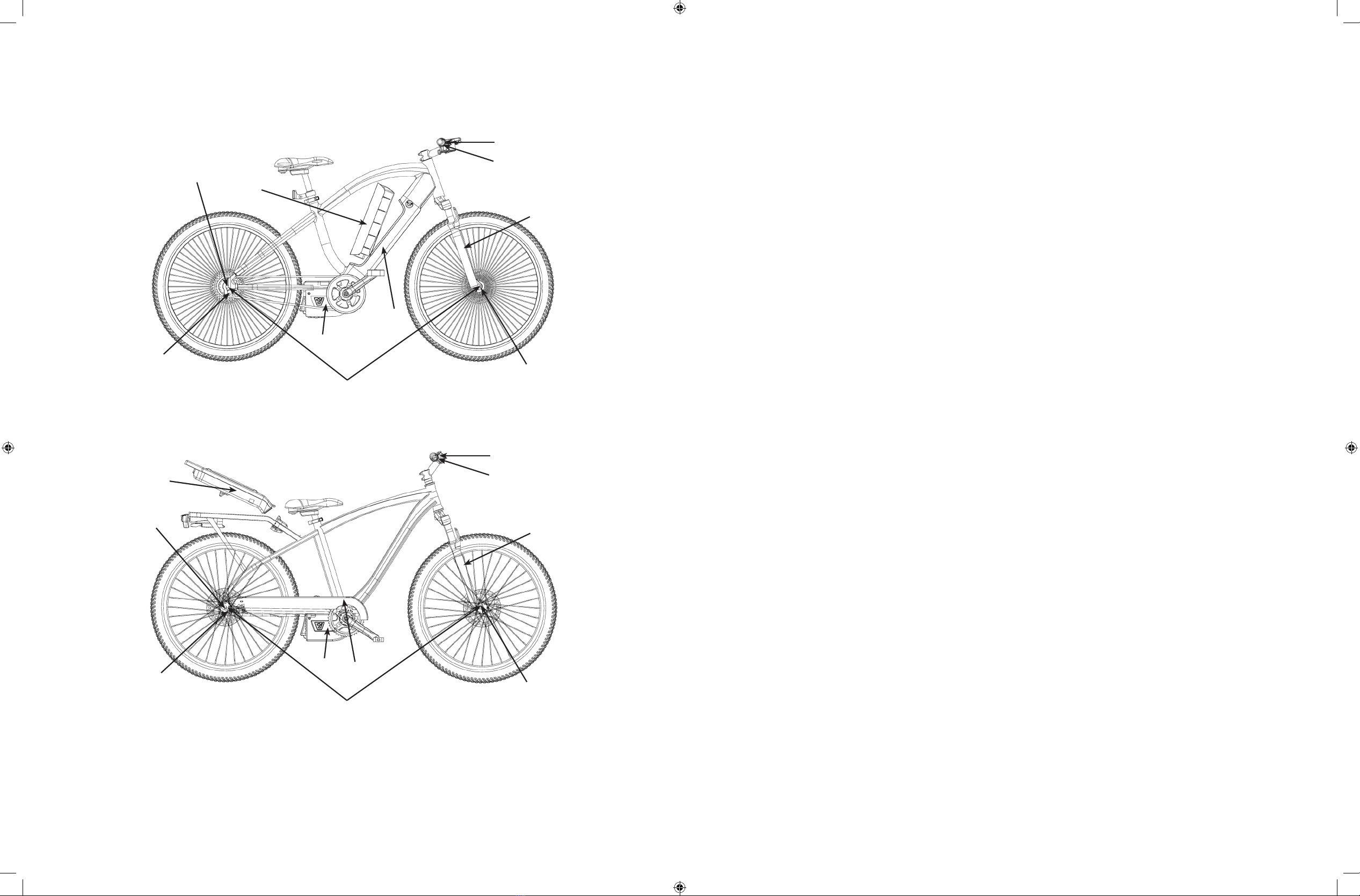
BICYCLE OVERVIEW.................................................................................................................................... 6
WARRANTY PROGRAM DETAILS................................................................................................................... 7
MOTOR SYSTEM COMPONENT WARRANTY........................................................................................... 7
NON-ELECTRIC COMPONENT WARRANTY............................................................................................. 7
SERVICING OF PARTS ..................................................................................................................................... 7
CHAPTER 2 ................................................................................................................................. 8
STEERING AND SUSPENSION................................................................................................. 8
HANDLEBAR REPLACEMENT......................................................................................................................... 8
REMOVAL....................................................................................................................................................... 8
INSTALLATION ............................................................................................................................................... 9
HANDLEBAR STEM ......................................................................................................................................... 9
REMOVAL....................................................................................................................................................... 9
INSTALLATION ............................................................................................................................................... 10
FRONT FORK REMOVAL/INSTALLATION....................................................................................................... 11
REMOVAL....................................................................................................................................................... 11
INSTALLATION ............................................................................................................................................... 12
CHAPTER 3 ................................................................................................................................. 13
BRAKES ....................................................................................................................................... 13
BRAKE LEVER REMOVAL/INSTALLATION..................................................................................................... 13
REMOVAL....................................................................................................................................................... 13
INSTALLATION .............................................................................................................................................. 13
BRAKE CABLE INNER WIRE .......................................................................................................................... 14
REMOVAL....................................................................................................................................................... 14
INSTALLATION ............................................................................................................................................... 14
BRAKE CALIPER REMOVAL/INSTALLATION ................................................................................................. 16
BRAKE CALIPER REMOVAL ........................................................................................................................ 16
INSTALLATION ............................................................................................................................................... 16
BRAKE PAD REPLACEMENT........................................................................................................................... 16
BRAKE DISC REMOVAL/INSTALLATION ........................................................................................................ 17
CHAPTER 4 ................................................................................................................................. 18
SHIFTER AND DERAILLEUR..................................................................................................... 18
REMOVAL....................................................................................................................................................... 18
INSTALLATION ............................................................................................................................................... 18
SHIFTER CABLE INNER WIRE REMOVAL/INSTALLATION .......................................................................... 19
REMOVAL....................................................................................................................................................... 19
INSTALLATION ............................................................................................................................................... 20
DERAILLEUR ..................................................................................................................................................... 21
DERAILLEUR LUBRICATION ....................................................................................................................... 21
DERAILLEUR ADJUSTMENT....................................................................................................................... 21
SETTING CABLE TENSION.......................................................................................................................... 22
DERAILLEUR INSTALLATION....................................................................................................................... 22
CHAPTER 5 ................................................................................................................................. 23
CHAIN AND CRANKSET ............................................................................................................ 23
CHAIN................................................................................................................................................................. 23
INSPECTION.................................................................................................................................................. 23
CHECKING CHAIN LENGTH ........................................................................................................................ 23
REMOVAL....................................................................................................................................................... 24
CLEANING...................................................................................................................................................... 24
INSTALLATION ............................................................................................................................................... 24
LUBRICATION ................................................................................................................................................ 25
CRANK ARM ...................................................................................................................................................... 25
REMOVAL....................................................................................................................................................... 25
INSPECTION.................................................................................................................................................. 26
INSTALLATION ............................................................................................................................................... 27
CHAINRING........................................................................................................................................................ 27
REMOVAL....................................................................................................................................................... 27
INSTALLATION ............................................................................................................................................... 27
CHAINRING WOBBLE CHECK......................................................................................................................... 28
PEDAL ............................................................................................................................................................... 28
REMOVAL....................................................................................................................................................... 28
INSTALLATION ............................................................................................................................................... 28
BOTTOM-BRACKET CARTRIDGE................................................................................................................... 29
REMOVAL....................................................................................................................................................... 29
INSTALLATION ............................................................................................................................................... 30
CHAPTER 6 ................................................................................................................................. 31
MOTOR SYSTEM ........................................................................................................................ 31
TROUBLESHOOTING DIAGNOSTIC GUIDE.................................................................................................. 31
ServiceManual_101212.indd 2-3 10/12/2012 12:25:43 AM

1
CHAPTER 1
GENERAL INFORMATION
In the pages that follow, EVantage will provide you with detailed instructions on how to service your
customers Electric Bicycles. We will cover both electric and non electric components for the bicycles, how to
service them, and service program procedure.
TERMS LEFT AND RIGHT
The terms left and right in this manual refer to the rider’s point of view when seated on the Polaris®electric
bicycle and facing forward. The right side of the Polaris®electric bicycle is the chain side. The left side is the
brake side.
NOTES, CAUTIONS AND WARNINGS
The terms NOTE, CAUTION and WARNING have specific meanings in this manual. A NOTE provides addi-
tional information to make a procedure easier or clearer.
A CAUTION emphasizes precautions that must be taken to avoid damage to tools or the Polaris®electric
bicycle. Disregarding a CAUTION could lead to mechanical damage.
A WARNING emphasizes a situation where negligence could lead to injury or death. Take WARNINGS
seriously. Failure to heed a WARNING could result in serious personal injury or death.
CONTROLLER CAP REMOVAL/INSTALLATION......................................................................................... 31
DUO DRIVE MOTOR SERVICE........................................................................................................................ 32
REAR WHEEL MOTOR REMOVAL .............................................................................................................. 32
REAR WHEEL MOTOR INSTALLATION....................................................................................................... 33
SMART CONTROLLER SERVICE.................................................................................................................... 34
SMART CONTROLLER REMOVAL .............................................................................................................. 34
SMART CONTROLLER INSTALLATION ...................................................................................................... 35
PRO-RIDE LITHIUM BATTERY SERVICE ....................................................................................................... 35
IC DASHBOARD SERVICE ............................................................................................................................... 36
IC DASHBOARD REMOVAL.......................................................................................................................... 36
IC DASHBOARD INSTALLATION.................................................................................................................. 36
THROTTLE SERVICE ....................................................................................................................................... 37
THROTTLE REMOVAL .................................................................................................................................. 37
THROTTLE INSTALLATION .......................................................................................................................... 37
ILLUSTRATION INDEX................................................................................................................ 38
ServiceManual_101212.indd 4-1 10/12/2012 12:25:44 AM

2 3
TROUBLESHOOTING / DIAGNOSTIC GUIDE
Motor sounds like it engages, but does
not move
Listen for clicking inside the motor
when actuated.
Display does not turn ON
Check cable connectors.
Charge battery for at least 4-6 hours.
Check battery voltage with multi-meter.
Replace controller as needed.
Inspect the charger lights are operating
properly.
Inspect both charger ports for damage.
Check battery lead wires and controller
connections.
Display turns ON but motor does not
engage through pedal assist
Check motor connections in controller
area.
Inspect torque sensor for damage or
faulty connection.
With multi-meter, check voltage from
controller lead to motor.
Display turns ON but does not engage
through throttle
Check motor connections in controller
area.
Check cable connections from throttle
for damage.
Inspect torque sensor for damage or
faulty connection.
With multi-meter, check voltage from
controller lead to motor.
Replace throttle as needed .
Display does not turn ON, but motor
engages
Check cable connections in controller
area.
Check cable connections within display
unit.
Replace dash as needed.
Brakes fail to cut motor when engaged
Check wires for damage.
Check controller connections.
Replace brake switch handles as
needed.
Replace controller as needed.
Replace motor as needed.
Motor engages and operates with
abnormal noise
Check connectors and controller.
Check motor, wheel/axle for damage.
Replace controller accordingly.
Replace motor, wheel/ axle.
Motor does not engage and has
abnormal noise
Check connectors and controller.
Check motor, wheel/axle for damage.
Replace controller.
Replace motor, wheel.
Motor wheel wobbles
Check motor/wheel/axles/spokes for
damage. Replace motor, wheel accordingly.
Display malfunction
Check connectors at controller.
Check connectors at display.
Check display and cables for damage.
Replace controller.
Replace display.
Replace display.
Throttle malfunction
Check throttle cable for damage.
Check connectors at controller.
Replace throttle.
Replace controller.
Battery charger malfunction
Check for good quality AC power, and
no extension cord usage.
Replace battery charger.
LED headlight malfunction
Check LED cable for damage. Replace LED.
Battery malfunction
FULL status: battery does not power
up bike.
EMPTY status: battery does not accept
charge.
Battery is frozen: Do not attempt to
recharge a frozen battery.
Check charger.
Check charger.
Replace battery.
Replace battery.
ServiceManual_101212.indd 2-3 10/12/2012 12:25:44 AM

4 5
Item # Ft.-Lb. Special Instructions
Brake caliper mounting
bolt
5-7 40-60 Apply Loctite 242
Brake disc bolt 6.2 55 Apply Loctite 242
Brake lever clamp bolt 3-3.9 26.5-34.7
Chainring bolt 6-8 53-71
Crank arm bolt 35-40 26-30 Apply grease to bolt threads
Derailleur anchor bolt 4.1 36.5
Derailleur mounting bolt 7.9 70
Front fender 3 26.5
Handlebar binder bolt 6 53 Apply grease to bolt threads
Handlebar stem clamp
bolt
12 106
Pedal 3-4.9 26.5-43.4 Apply grease to stud threads
Rear axle nut 60-65 44-48
Rear fender bolt 4 35
Rear fender stay bolt 2 17.7
Seat post clamp bolt 10-12 89-106
Shifter set screw 3-3.9 26.5-34.7
Shock absorber bolt 16-20 12-14.5 Apply Loctite 242
Swingarm bolt 18-22 13-16 Apply Loctite 242
Throttle set screw 3-3.9 26.5-34.7
Torque arm bolt 9-10 80-89
SERIAL NUMBER IDENTIFICATION
The serial ID number is an 8-digit code located either on the front or back of the bicycle headtube. This
number should be referenced when registering warranty or service claims.
TOOLS
The following special tools are needed when servicing the Vector EV200PH:
Tool Part Number
Star shaped wrench set Park TWS-2
Head cup remover Park RT-1
Bearing cup press Park HHP-3
Hex wrench set: 4mm, 5mm, 6mm Park AWS-1
Hex wrench set Park AWS-11C
Hex wrench set: 2mm, 5mm, 3mm Park AWS-3
Fourth-hand cable stretcher Park BT-2
Chain checker Park CC-2C
Chain breaker (screw type) Park CT-3
Crank wrench Park CCW-14R
Cable and housing cutter Park CN-4C
Gearclean brush Park GSC-1
32mm & 36mm head wrench Park HCW-15
Pedal wrench Park PW-3
Spoke wrench (black) Park SW-0
Spoke wrench (red) Park SW-2
Tire lever set Park TL-1C
Freewheel tool Part Tool FR-1
Bottom-bracket-cartridge tool Park Tool BBT-2
SPECIFICATIONS
Table 1: Electrical Specifications
Component Specification
Battery 29.6V
Type Lithium Manganese
Capacity 6Ah (178 watt/hr)
Charger EVantage Smart Battery Charger
Input 120vAC, 60Hz
Output
Table 2: Parts
Item # Ft.-Lb. Special Instructions
Bottom-bracket cartridge
adapter ring
29.4 21.7-28 Apply grease to the threads
Brake caliper anchor bolt 5-7 40-60
Brake caliper CPS bolt 8-10 70-90
ServiceManual_101212.indd 4-5 10/12/2012 12:25:44 AM

6 7
WARRANTY PROGRAM DETAILS
The warranty program is detailed below. Warranty dating in all cases is set from date of purchase. Bicycle
owner must show proof of date of purchase, and also proof that they are the initial purchaser. Any resale of
the bike voids the warranty.
Motor System Component Warranty
DuoDrive Motor (1 year from date of purchase)
Smart Controller (1 year from date of purchase)
ProRide Lithium Battery (1 year from date of purchase)
IC Dashboard Display (1 year from date of purchase)
Throttle (1 year from date of purchase)
All other motor components (1 year from Date of purchase)
Non-Electric Component Warranty
6 months from date of purchase (excluding tires, tubes, spokes, chain)
SERVICING OF PARTS
When a customer comes in with a customer service request, hopefully they have already contacted EVantage
customer support directly, and we have directed them to you. If they have come in without previously
speaking with our customer service team you can either contact us by phone or submit a service request
form at www.polarisebikes.com/servicerequest . One of our customer service members would be more than
happy to help you diagnose the problem and find the accurate solution.
All motor system parts are stocked in our warehouse, and can be made available to you as needed.
All non-motor system parts, are not stocked in warehouse. Please order replacement bicycle parts either from
your local parts distributor, or through our parts distribution network. If ordered directly by you, component
costs can be used as credit towards your next POLARIS electric bicycle purchase, only if the product is still
under warranty.
Labor Costs: Labor can be billed back to EVantage at a hourly rate of $10/hr, with a maximum labor cost of
$40.00 per service project. Labor costs will be credited to your account, and can be deducted from any future
order.
GENERAL WARRANTY INFORMATION
Components To Become Familiar With Which Are Covered Under Warranty
Bicycle Overview
IN-FRAME MODELS (EV206PH-B, EV206PH-S)
1
7
8
2
6
4
3
5
9
10
REAR RACK MODELS (EV306PH-B, EV306PH-S,
EV316PH-G, EV316PH-L, EV407PH-G, EV407PH-B, EV417PH-W, EV417PH-B
1
7
8
2
64
3
5
9
10
1. DuoDrive Rear Hub Motor
2. In Frame ProRide Lithium-Ion Battery
3. Information Center Dashboard
4. Charging Socket (opposite side)
5. Throttle
6. Smart Controller
7. SRAM x7, 8 Speed Derailleur
8. Dual Disk Brakes
9. Suspension Fork
10.Front Quick Release Axle/Wheel
ServiceManual_101212.indd 6-7 10/12/2012 12:25:45 AM

8 9
FIGURE 2-3
Installation
1. Install the handlebar by reversing the removal procedures.
a. Make sure the handlebar is centered and properly oriented within the handlebar stem.
b. Apply grease to the handlebar binder bolts (Figure 2-3), and evenly tighten the bolts in a star pattern so
the gap at the top of the clamp is the same as the gap at the bottom. Torque the handlebar binder bolts
to the specification in Table 5.
c. Slide the reflector, each brake lever, throttle, display, shifter onto their respective handlebar ends.
d. Install handlebar grip onto each handlebar end.
e. Position the throttle, shifter and display relative to its handlebar grip as noted during removal. Tighten
their set-screws and clamp bolts.
f. Slide each brake lever so its bracket seats against the throttle or shifter. Rotate the brake lever to the
position noted during removal, and torque the brake lever clamp bolts to the specification in Table 5.
g. Rotate the throttle and shifter so their barrels rest against the brake lever. Torque the throttle set screw
and the shifter clamp bolt to the specifications in Table 5.
HANDLEBAR STEM
Removal
1. If necessary, remove the handlebar binder bolts (Figure 2-3), and remove the handlebar from the
handlebar stem. Use a bungee cord to suspend the handlebar from the frame.
2. Loosen the handlebar stem bolt from the top of the handlebar stem (A, Figure 2-4). You may remove bolt
and cap.
FIGURE 2-4
B
C A
CHAPTER 2
STEERING AND SUSPENSION
WARRANTY NOTE: Steering and front suspension fall under “non-electric” component warranty. Applicable
warranty is 6 months from date of purchase. Any service issue resulting from misuse of bicycle is not
covered under this warranty and user shall be responsible for all charges .
HANDLEBAR REPLACEMENT
Removal
1. Note the position of the throttle and the shifter relative to its handlebar grip. If necessary, measure the
gap between each item and its handlebar grip or make a drawing so these components can be reinstalled
with the proper positioning and orientation. Also note the orientation of the handlebar within the handlebar
stem.
2. Remove the left and right handlebar grip.
3. Loosen the throttle set screw (A, Figure 2-1), shifter clamp bolt (A, Figure 2-2), the reflector clamp bolt
screw, the clamp bolt on each brake lever (B, Figure 2-2), and display unit set-screw. (B, Figure 2-1)
4. Remove the handlebar binder bolts (Figure 2-3).
5. Lower the handlebar from the handlebar stem.
6. Slide the throttle, shifter, display, brake levers and the reflector assembly from the handlebar ends and
remove the handlebar.
FIGURE 2-1
B
A
FIGURE 2-2
B
A
B
ServiceManual_101212.indd 8-9 10/12/2012 12:25:47 AM

10 11
c. With the front wheel off the ground, turn the handlebar from full stop to full stop. The fork should turn
smoothly.
d. Torque the handlebar stem clamp bolts (A, Figure 2-4) to the specification in Table 5.
e. Tighten the handlebar stem bolts (B, Figure 2-4) an additional 30 degree (clockwise).
f. With the front wheel off the ground (A, Figure 2-4), again turn the handlebar from full stop to full stop.
The fork should turn smoothly.
FRONT FORK REMOVAL/INSTALLATION
Removal
The front fork is not serviceable. If the fork is damaged, it must be replaced.
1. Remove the handlebar (this chapter).
2. Remove cable holder bolt with 3mm hex wrench (A, Figure 2-8) and release the front brake cable
(B, Figure 2-8) from the holder.
3. Remove the caliper mounting bolts (A, Figure 2-10), and slide the front brake caliper (B, Figure 2-9) from
the brake disc. Suspend the caliper with a bungee cord (A, Figure 2-9).
4. Remove the front wheel.
FIGURE 2-8
B
A
FIGURE 2-5
FIGURE 2-6
FIGURE 2-7
3. Loosen the handlebar stem clamp bolts (B, Figure 2-4)
4. Lift the handlebar stem (C, Figure 2-4) from the head tube.
5. If necessary, remove the upper bearing by performing the following:
a. Lower the fork within the head tube as needed, and remove headset spacer, seal and bearing cover
(Figure 2-5).
b. First remove the upper bearing with Park RT-1 head cup remover, then the lower bearing (Figure 2-6).
Installation
1. If removed, install the upper bearing by performing the following:
a. Press top and bottom bearing cup and bearing using Park HHP-2 Headset Press (Figure 2-7).
b. Press the front fork up into the head tube.
c. Install the bearing cover, then the seal and headset spacer
2. Set the handlebar stem onto the head tube, and turn in the handlebar stem bolt and washer (A, Figure 2-4).
WARNING!
The handlebar stem bolt and clamp bolt must be tightened as described below. Overtightening
the stem bolt can damage the headset bearings. If the handlebar stem clamp bolt is not properly
torqued, the fork may not turn when the handlebar is turned.
3. Perform the following to set the headset bearings and to secure the handlebar stem in place and in
alignment with the front wheel.
a. Tighten the handlebar stem bolt (B, Figure 2-4) until there is no play in the steer- ing.
b. Tighten the stem bolt an additional 120 degrees (clockwise), and then loosen it 90 degrees
(counterclockwise).
ServiceManual_101212.indd 10-11 10/12/2012 12:25:48 AM

12 13
CHAPTER 3
BRAKES
WARRANTY NOTE: Brakes fall under “non-electric” component warranty. Applicable warranty is 6 months
from date of purchase. Any service issue resulting from misuse of bicycle is not covered under this warranty
and user shall be responsible for all charges.
BRAKE LEVER REMOVAL/INSTALLATION
Removal
1. Note the position of the throttle, shifter and display relative to its handlebar grip. If necessary, measure the
gap between the item and its handlebar grip or make a drawing so these components can be reinstalled
with the proper positioning and orientation. Also note the orientation of the handlebar within the handlebar
stem.
2. Disconnect the electric brake lever connector at the controller box.
3. At the brake lever, loosen the adjuster locknut (A, Figure 3-1) and turn the adjuster barrel (B, Figure 3-1)
from the brake lever.
4. Turn the adjuster barrel and the locknut until their slots align with the slot in the brake lever housing.
5. Pull the cable housing from the adjuster barrel (B, Figure 3-1), and slide the inner wire (C, Figure 3-1)
through the slots in the lever housing, adjuster barrel and locknut.
6. Press the brake lever toward the handlebar, and disconnect the inner wire end (A, Figure 3-2) from the
anchor (B, Figure 3-2) on the brake lever.
7. Remove the handlebar from the handlebar end.
Installation
1. Slide the new brake lever onto the end of the handlebar.
2. Make sure the slots in the adjuster barrel and the locknut align with the slot in the brake lever housing
(Figure 3-1).
FIGURE 3-1
BAC
3. Connect the end of the brake cable inner wire (B, Figure 3-2) to the anchor (A, Figure 3-2) on the brake
lever.
FIGURE 2-9
B
A
FIGURE 2-10
5. Remove the handlebar stem and the upper bearing as described in this chap- ter.
6. Lower the fork until the fork column clears the head tube, and remove the front fork.
7. Visually inspect the seal, bearing cover, spacer and stem cap for any damage (Figure 2-10).
8. Manually turn the bearing inner race, and confirm that the bearing rotates smoothly.
9. Inspect the lower bearing in the head tube. If either bearing is faulty, replace both bearings as a set.
Installation
1. After installing the headset as previously referred, slide the fork column up into the head tube until the
lower-bearing collar rests against the lower bearing.
2. Install the handlebar stem as described in this chapter.
3. Install the front wheel.
4. Carefully slide the front brake caliper onto the brake disc so the disc does not mar the brake pads. Apply
Loctite 242 to the threads of caliper mounting bolts (A, Figure 2-9), and evenly tighten the bolts. Torque
the caliper mounting bolts to the specification in Table 5.
5. Install the handlebar as described in this chapter.
ServiceManual_101212.indd 12-13 10/12/2012 12:25:50 AM

14 15
FIGURE 3-2
B
A
4. Pull the cable housing, and slide the cable inner wire (C, Figure 3-1) through the slots in the brake lever,
adjuster barrel (B, Figure 3-1) and locknut (A, Figure 3-1). Seat the cable housing ferrule into the adjuster
barrel.
5. Install a handlebar grip onto the handlebar end.
6. Slide the brake lever so its bracket seats against the throttle or shifter. Rotate the brake lever to the
position noted during removal, and torque the brake lever clamp bolt to the specification in Table 5.
BRAKE CABLE INNER WIRE
Removal
The cable inner wire can be replaced without removing the cable housing.
1. Clip the cable ferrule from the brake cable inner wire.
2. Turn out the anchor bolt (A, Figure 3-3), and release the inner wire from the pinch mechanism.
4. Pull the cable housing and inner wire from the caliper barrel adjuster.
5. At the brake lever, loosen the adjuster locknut (A, Figure 3-1) and turn the adjuster barrel (B) from the
brake lever.
6. Turn the barrel adjuster and the locknut (A, Figure 3-1) until their slots align with the slot in the brake lever
housing.
7. Pull the cable housing from the adjuster barrel, and slide the inner wire (C, Figure 3-1) from the slots in
the housing, adjuster barrel and locknut.
8. Press the brake lever toward the handlebar, and disconnect the inner wire end (C, Figure 3-1) from the
anchor (B) on the brake lever.
9. Pull the inner wire from the cable housing until the far end emerges from the cable housing (A, Figure 3-2).
Installation
A fourth-hand tool (Park Took BT-2) is needed for this procedure.
1. Apply oil to the inside of the cable housing.
2. Insert the inner wire through the brake lever end of the cable housing until the wire emerges from the
caliper end of the housing.
3. Press the brake lever toward the handlebar, and connect the inner wire end (B, Figure 3-2) to the anchor
(A, Figure 3-2) on the brake lever.
FIGURE 3-3
B
A
C
4. Pull the cable housing, and slide the cable inner wire (C, Figure 3-1) through the slots in the brake lever,
adjuster barrel (B, Figure 3-1) and locknut (A, Figure 3-1). Seat the cable housing ferrule into the adjuster
barrel.
5. At the caliper, turn the barrel adjust all the way into the caliper.
6. Feed the inner wire through the caliper barrel adjuster, and seat the cable housing in the adjuster.
7. Route the inner cable through the pinch mechanism on the caliper.
8. Use the fourth-hand tool to remove the slack from the cable, and torque the brake caliper anchor bolt (A,
Figure 3-3) to the specification in Table 5.
9. Loosen the CPS bolts with 5mm hex wrench(B, Figure 3-3) so the caliper can move freely.
10.Turn the inboard pad adjuster (C, Figure 3-3) clockwise (inward toward the caliper) until the brake disc
(A, Figure 3-4) is centered within the caliper body (B, Figure 3-3). The caliper is properly adjusted if the
space on each side of the brake disc is the same.
11.Pull in and hold the brake lever. Check that the rotor is still centered within the caliper body.
12.Pull in and hold the brake lever. Torque the CPS bolts (B, Figure 3-3) to the specification in Table 5 while
holding the brake lever in.
13.Release the brake lever, and spin the wheel. Listen for the sound of the inboard pad rubbing against the
brake disc.
14.If rubbing is noted, turn the inboard pad adjuster counterclockwise (out from the caliper) two or three
clicks, and recheck.
15.Repeat Steps 13 and 14 as needed.
16.Trim the inner wire end so its end extends no more than 20 mm (3/4 in.) beyond the anchor. Crimp a new
cable ferrule onto the cable end.
17.Use the barrel adjuster (B, Figure 3-1) at the brake lever to remove any cable slack. Turn the adjuster
outward until brake lever freeplay is eliminated. However, do not go so far that the caliper torque arm is
moved. Make sure the caliper torque arm is completely released, and tighten the adjuster locknut (A)
against the brake lever housing.
ServiceManual_101212.indd 14-15 10/12/2012 12:25:50 AM

16 17
BRAKE CALIPER REMOVAL/INSTALLATION
Brake Caliper Removal
The following procedure shows the removal of a front caliper. This procedure also applies to a rear caliper.
1. If the caliper is being replaced, perform the following:
a. Clip the cable ferrule from the brake cable inner wire.
b. Turn out the anchor bolt (A, Figure 3-3), and release the inner wire from the pinch mechanism.
c. Pull the cable housing and inner wire from the caliper barrel adjuster. 2. Remove the caliper mounting
bolts (A, Figure 3-5), and slide the brake caliper (B) from the brake disc.
Installation
FIGURE 3-4
B
A
1. Carefully slide the brake caliper over the brake disc. Seat the caliper against the inboard side of the
mounting bosses on the fork slider or swingarm.
2. Apply Loctite 242 to the threads of the caliper mounting bolts, and turn in the bolts (A, Figure 3-4, typical).
Torque the brake caliper mounting bolts to the specification in Table 5.
3. If necessary, complete caliper installation by performing Steps 5-17 of Brake Cable Inner Wire Installation
(this chapter).
BRAKE PAD REPLACEMENT
The following procedure shows brake pad replacement on a rear caliper. This procedure also applies to a
front caliper.
1. Turn the inboard pad adjuster with 5mm allen bolt (A, Figure 3-5) counterclockwise (out from the cali-
per).
2. Pull the pad spreader from between the brake pad arms.
3. Remove the outboard brake pad (B, Figure 3-5) and then the inboard pad (C, Figure 3-5) from the caliper.
4. Install the pad on the outboard side of the brake disc. Install the pad on the inboard side of the disc. Make
sure the pad material on each brake pad faces the brake disc.
5. Gently squeeze the tangs of the pad spreader and press the spreader into place between the brake pad arms.
FIGURE 3-5
A
CB
BRAKE DISC REMOVAL/INSTALLATION
1. Remove the relevant wheel.
2. Turn out the brake disc bolts (A, Figure 3-6), and remove the disc from the wheel hub.
3. Install the disc so its arrow (B, Figure 3-6) points in the direction of forward wheel rotation.
4. Apply Loctite 242 to the brake disc bolts, and evenly tighten the bolts in a crisscross pattern. Torque the
brake disc bolts (A, Figure 3-6) to the specification in Table 5.
FIGURE 3-6
A
B
ServiceManual_101212.indd 16-17 10/12/2012 12:25:51 AM

18 19
CHAPTER 4
SHIFTER AND DERAILLEUR
WARRANTY NOTE: Shifter and derailleur fall under “non-electric” component warranty. Applicable warranty
is 6 months from date of purchase. Any service issue resulting from misuse of bicycle is not covered under
this warranty and user shall be responsible for all charges.
SHIFTER REMOVAL/INSTALLATION
Removal
1. Note the position of the shifter relative to the right handlebar grip. If necessary, measure the gap or make
a drawing so the shifter can be properly positioned during installation.
2. Remove the left handlebar grip
3. Loosen the brake lever clamp bolt and slide the brake lever from the handle bar.
4. Loosen the shifter clamp bolt (A, Figure 4-1), and slide the shifter from the handlebar end.
FIGURE 4-1
A
C
B
Installation
1. Slide the shifter onto the handlebar end.
2. Completely install the handlebar grip.
3. Move the shifter to its position relative to the handlebar grip as noted during removal. Temporarily tighten
the clamp bolt (A, Figure 4-1) enough to hold the shifter in position.
4. If the brake lever was moved perform the following:
a. Slide the brake lever so its bracket rests against the shifter.
b. Rotate the brake lever to the position noted during removal, and torque the brake lever clamp bolt (B,
Figure 4-1) to the specification in Table 5.
5. Rotate the shifter so its barrel seats against the brake lever, and torque the shifter set screw (A, Figure
4-1) to the specification in Table 5.
SHIFTER CABLE INNER WIRE REMOVAL/INSTALLATION
Removal
The cable inner wire can be replaced without removing the cable housing.
1. Operate the shifter and move the chain to the smallest cog (high gear).
2. Clip the cable ferrule from the cable end (A, Figure 4-2).
FIGURE 4-2
B
A
C
3. Loosen the anchor bolt (B, Figure 4-2), and release the cable inner wire from the from the derailleur pinch
mechanism.
4. Remove the cable housing and inner wire from the derailleur cable guide (C, Figure 4-2).
5. Remove the hand grip from the left handlebar end.
6. Loosen the shifter clamp bolt (A, Figure 4-1) and the brake lever clamp bolt (B, Figure 4-1). Slide the
brake lever out of the way.
7. Unscrew shifter cable cap.
FIGURE 4-3
8. Push the inner wire into the shifter until the cable end emerges from the socket in the shifter drum
(Figure 4-4).
9. Pull the inner wire from the shifter drum (Figure 4-3).
ServiceManual_101212.indd 18-19 10/12/2012 12:25:53 AM

20 21
FIGURE 4-4
Installation
A fourth-hand tool (Park Took BT-2) is needed for this procedure.
1. Clean the shifter housing, however, do not use solvents. They could attack the plastic used in these parts.
2. Preset the derailleur adjustment screws before installing the inner wire.
a. Stand behind the derailleur, and check the position of the guide pulley. It should
align with the smallest cog (high gear) as shown in Figure 4-4.
b. If necessary, adjust the outward limit by turning the H-screw (high-gear limiter screw). Tightening the
H-screw moves the guide pulley inward. Loosening the screw moves the pulley outward.
c. Manually move the derailleur to its innermost position. Hold the derailleur against the stop, and check
the guide pulley. It should align with the largest cog (low gear) shown in Figure 4-5.
d. If necessary, adjust the inward limit by turning the L-screw (low-gear limiter screw). Tighten the L-screw
to adjust the derailleur outward. Loosen the screw to adjust the derailleur inward.
FIGURE 4-5
3. Insert the free end of the wire through the socket in the shifter drum until the wire’s barrel end is seated in
the socket (Figure 4-3).
4. Check shifter operation by pulling the wire and clicking the shifter. The inner wire should move in and out,
and the shifter should click.
5. Insert the inner wire through the ferrule in the upper end of the cable housing. Feed the wire through the
housing until the wire emerges from the housing end at the derailleur.
6. At the shifter, slide the upper housing along the inner wire, and seat housing fer- rule in the barrel adjuster.
7. Install the shifter cable cap onto the shifter.
8. At the derailleur, insert the inner wire through barrel adjuster and through the cable pinch mechanism.
Make sure the lower cable ferrule seats in the derailleur cable guide (C, Figure 4-2) and the inner wire is
properly routed through the pinch mechanism.
9. Manually tighten the anchor bolt (B, Figure 4-2) so the derailleur cable guide and inner wire is secured in
the pinch mechanism groove. Look directly at the pinch mechanism. The tab on the pinch plate should be
inboard of the inner wire.
10.Loosen the anchor bolt as seen in Figure 4-9. Pull the slack from the inner wire with the fourth hand tool,
and torque the derailleur anchor bolt (B, Figure 4-2) to the specification in Table 5. Make sure the inner
wire still sits in the pinch-mechanism groove.
11.Cut the excess from the inner wire. Leave a couple of inches for future adjust- ment.
12. Fit a new cable ferrule (A, Figure 4-2) over the inner wire end, and crimp the fer- rule in place.
13.Install the shifter and brake lever onto the handlebar as described in this chapter.
14.Adjust the derailleur and then the cable tension as described in this chapter.
DERAILLEUR
Derailleur Lubrication
Lubricate to the following components on the derailleur.
1. Each edge of the pulley-wheel dustcap.
2. Both ends of each pivot on the parallelogram.
3. The mounting bolt treads.
4. The barrel adjuster threads.
5. The anchor bolt treads.
Derailleur Adjustment
Three screws are used to adjust the derailleur. The H-screw (high-gear limiter screw) sets the outward limit of
the derailleur’s movement. The L-screw (low-gear limiter screw) sets its inward limit. The B-screw adjusts the
distance between the bottom of the cogset and the derailleur’s guide pulley.
A fourth–hand tool (Park Tool BT-2) is required to perform this procedure
1. Check the cable attachment to the derailleur pinch mechanism.
a. Check the position of the inner wire in the pinch mechanism. The wire should follow the groove in the
pinch plate, and the pinch plate tab should be inboard of the wire when you look directly at the pinch-
mechanism stud.
b. Loosen the anchor bolt (B, Figure 4-2). Use the fourth-hand tool to pull the slack from the inner wire.
c. Torque the derailleur anchor bolt to the specification in Table 5.
d. Check that the inner cable still sits within the groove in the pinch-mechanism plate.
2. Set the derailleur as close as possible to the cogset by performing the following.
a. Shift the chain to the largest cog (low gear).
b. Completely loosen the B-screw. c. Back-pedal, and check for bouncing at the guide pulley (Figure
4-11). The B-screw is too loose if bouncing is noticed. d. Tighten the B-screw (Figure 4-10) one turn,
and repeat the bounce check.
ServiceManual_101212.indd 20-21 10/12/2012 12:25:54 AM

22 23
3. Set the derailleur’s outward limit as follows:
a. Shift the derailleur so the chain sits on the smallest cog (high gear).
b. Stand behind the derailleur, and check the position of the guide pulley. The pulley should align with the
smallest cog as shown in Figure 4-4.
c. If necessary, use the H-screw to adjust the outward limit. Tighten the H-screw to move the derailleur
inward; loosen the H-screw to move it outward.
4. Set the derailleur’s inward limit as follows:
a. Shift the derailleur so the chain rests on the largest cog (low gear).
b. Stand behind the derailleur, and check the position of the guide pulley. The pulley should align with the
largest cog as shown in Figure 4-5.
c. If necessary, use the L-screw to adjust the inward limit. Tighten the L-screw to move the derailleur
outward; loosen the L-screw to move it inward.
Setting cable tension
A fourth–hand tool (Park Tool BT-2) is required to perform this procedure.
1. Loosen the derailleur anchor bolt (B, Figure 4-2).
2. Turn the derailleur barrel adjuster (C, Figure 4-2) to its fully-in position, and then back out the adjuster
three full turns.
3. Turn the Turn the derailleur cable guide to its fully-in position, and then back it out one full turn.
NOTE: Do not pull the inner wire so much that the derailleur begins to move.
4. Use a fourth-hand tool to pull the slack out of the inner wire.
5. Torque the derailleur anchor bolt (B, Figure 4-2) to the specification in Table 5. Check that the inner wire
still sits within the pinch-mechanism groove.
Derailleur installation
1. Lubricate the derailleur as described earlier in this chapter.
2. Align the mounting bolt (D, Figure 4-2) with the hole in the hanger.
3. Rotate the derailleur clockwise so the stop tab on the derailleur mounting plate (or the end of the B-screw)
sits forward (clockwise) of the stop tab on the derailleur hanger.
4. Turn the mounting bolt into the hanger. Finger-tighten the bolt.
5. Rotate the derailleur counterclockwise until the derailleur stop tab presses against the stop tab on the
hanger.
6. Torque the derailleur mounting bolt (C, Figure 4-2) to the specification in Table 5.
CHAPTER 5
CHAIN AND CRANKSET
WARRANTY NOTE: Chain and crankset fall under “non-electric” component warranty. Applicable warranty
is 6 months from date of purchase. Any service issue resulting from misuse of bicycle is not covered under
this warranty and-user shall be responsible for all charges.
CHAIN
Inspection
The chain inspection tool (Park Tool CC-2C) is needed for this service.
1. Following the manufacturer’s instructions, install the chain inspection tool onto the chain. Both of the tool’s
pegs must sit inside a chain link.
2. Rotate the tool’s dial so the pegs press against the inside of the chain rollers.
3. The number opposite the V-notch on the dial indicates the chain’s condition.
a. 0-1: the chain is in good condition.
b. 1-2: the chain is moderately worn.
c. 2-3: the chain is approaching the wear limit.
d. 3 or more: the chain is worn beyond the wear limit.
Checking Chain Length
1. Secure the POLARIS electric bicycle in a stand at an angle that matches the angle when the bike sits
upright on a level surface.
2. Shift the derailleur and move the chain to the outermost cog (high gear).
3. Check the angle of a line drawn through the center of the two derailleur pulleys relative to the ground or
floor.
a. The chain length is perfect if this line is perpendicular (75 degrees) to the ground (Figure 5-1).
b. Chain length is acceptable if the ten- sion pulley sits 1.75 in. or less forward or rearward of the guide
pulley.
FIGURE 5-1
FIGURE 5-2
4. Visually inspect the chain. The chain is too long if the upper run sags as shown in Figure 5-2.
5. Shift the derailleur and move the chain to the innermost cog.
6. Check the chain as it passes through the derailleur. The chain should bend twice as passes through the
derailleur. The chain is too short if it does not.
ServiceManual_101212.indd 22-23 10/12/2012 12:25:54 AM

24 25
Removal
A chain breaker (Park CT-3) is needed for removing and installing the chain.
1. Shift the derailleur and move the chain to the smallest cog (high gear).
2. Inspect the drive pin of the chain breaker. Replace the tool if the pin is not straight.
CAUTION
Some chain breakers have two cradles. Use cradle furthest from the guide pin when removing or
installing the chain. Use the cradle closest to the guide pin when adjusting a tight link. Always
use the correct cradle for the task.
3. Install the chain breaker onto a link in the chain’s lower run. Fully seat the rollers in the tool’s cradle, and
center the drive pin on a chain rivet.
4. Turn the tool handle until the drive pin just touches the rivet.
NOTE: Press the rivet the minimum distance needed to separate the chain and stop. Do not drive the
rivet completely from the inner plate on the inboard side of the chain. The chain can be separated once
the rivet extends 0.5 to 1.0 mm into the inside of the inner chain plate.
5. Turn the tool handle five full turns, and remove the tool.
6. Flex the chain laterally as needed to separate the links.
7. Carefully pull the end with the rivet, and remove the chain from the derailleur, and chainring.
Cleaning
1. Soak the chain in solvent.
2. Clean both side of the chain with a stiff brush.
3. Exercise caution when brushing the rollers, but make sure the rollers are completely clean.
4. Rinse the chain in clean solvent, and dry it with compressed air.
Installation
1. Route the non-riveted end of the chain under and around the rear of the derail- leur tension pulley.
Following the derailleur cage, feed the chain up the front and over the top of the guide pulley. Once the
chain emerges from the derailleur cage, route it under and around the smallest cog (high gear).
2. Put chain around front chain ring
3. Move the chain so the two free ends meet in the lower chain run.
4. Slip the non-riveted end of the chain over the rivet protruding from the other end of the chain.
5. Install the chain tool onto the chain. Pay attention to the following:
a. If the tool has two cradles, use the cradle furthest away from the tool handle.
b. Fully seat the rollers on the tool cradle.
c. Center the drive pin on the rivet.
d. Make sure the side plates are properly aligned.
6. Turn the tool handle, and drive the rivet until it is centered within the link. The distance from the outer side
plate to the end of the rivet should be the same on each side of the chain (Figure 5-3).
FIGURE 5-3
Lubrication
CAUTION
Use oil designed for bicycles. Automotive and household oils are unsuitable for the POLARIS
electric bicycle chain.
NOTE: Do not apply excessive amounts of lubricant to the chain. Excess oil accumulates dirt which
accelerates chain wear.
1. Oil the contact areas between the inner and outer side plates on each link (A, Figure 5-4), and oil the
contact areas between the inner side plates and each end of the rollers (B, Figure 5-4).
FIGURE 5-4
A
B
2. If the chain is installed on the POLARIS electric bicycle, back pedal for 30 seconds. If the chain is not
installed, wiggle the chain for 30 seconds. This helps the lubricant penetrate the crevices within the chain.
3. Wipe excess oil from the chain with a clean, lint-free cloth.
CRANK ARM
Removal
A cotterless crank wrench (Park Tool CCW-14R) is need when removing the crank arm.
1. If the pedal requires the service, remove the pedal from the crank arm.
2. Pull the plug from the crank arm, and examine the crank arm bolt (Figure 5-5).
FIGURE 5-5
3. Turn out and remove the crank arm bolt.
4. Inspect the position of the spindle end. It should be recessed within the crank-arm square hole. The crank
arm is excessively worn, if the spindle end is flush with the surface of the crank-arm square hole. Replace
the crank arm.
5. If the crank arm will be reinstalled, mark a corner of the spindle end and a corresponding mark on the
crank arm. The marks will facilitate assembly.
ServiceManual_101212.indd 24-25 10/12/2012 12:25:56 AM

26 27
6. Carefully turn the crank-wrench body onto the crank arm. Finger-tighten the body until it bottoms in the
arm. Use an adjustable wrench to snug the body into the crank arm, and turn in the crank- wrench handle
(Figure 5-6).
FIGURE 5-6
CAUTION
If the crank-wrench body rotates or if the body pulls from the crank arm when the crank wrench
is tighten, remove the crank- wrench body and identify the problem. The crank wrench threads
may be dam- aged. Correct the problem before proceeding.
7. If removing the right arm, remove the chain from the chainring.
8. Turn the crank-wrench handle clockwise, and press the crank arm off the spindle.
Inspection
1. Inspect the spindle flats for signs of a loose or worn crank arm. If the crank-arm marks on the spindle flats
extend along the entire surface of the flats, the crank arm is worn. Replace it.
2. Inspect the square hole in the crank arm (Figure 5-7). The flats of the hole should be straight and even.
Replace the crank arm if its square hole shows signs of wear or damage.
FIGURE 5-7
3. Inspect the crank arm for cracks or other signs of wear. Pay particular attention to the area around the
mounting holes at either end of the crank arm. Replace the crank arm if it is worn.
4. Inspect the spokes (spider arms) (Figure 5-8) on the right crank arm. Replace the crank arm if any spoke
is cracked or shows signs of damage.
FIGURE 5-8
Installation
When installing both crank arms, install the right crank arm first, and then install the left crank arm so it is
oriented 180 degrees from the right arm.
1. When installing a new right crank arm or a new chainring, check chainring wobble as described in this
chapter.
2. Use acetone or alcohol to clean the flats of the spindle.
3A. When reinstalling an old crank arm, line up the spindle to the crank arm hole. Tap the crank arm onto the
spindle with a plastic mallet.
3B. If installing a new right crank arm and/ or new chainring, perform the following:
a. Rotate the spindle so the reference mark from the chainring wobble test is at the position that produced
the least amount of wobble.
b. Fit the chainring into the chain.
c. Rotate the derailleur forward, and seat the crank arm onto the spindle so the arm sits at 6 o’clock.
d. Tap the crank arm with a plastic mallet.
4. Apply grease to the crank arm bolt. Turn in the bolt, and torque crank arm bolt (Figure 5-5) to the
specification in Table 5. 5. Repeat for the left crank arm if necessary. Make sure the left crank arm is 180
degrees opposite the right crank arm.
CHAINRING
Removal
1. Remove the right crank arm as described in this chapter.
2. Inspect the inboard side of the crank arm/chainring. Note that the chainring is mounted so the cutout with
the tab aligns with the crank arm. The chainring must be mounted in this position during installation.
Installation
1. Fit the chainring onto the crank arm in the same position as removal.
2. Position the chainring so the cutout with the tab aligns with the crank arm.
3. Apply oil to the threads of the chainring bolts.
4. Fit the chain ring nut onto the inboard threads of the crank arm and tighten (according to table 5).
ServiceManual_101212.indd 26-27 10/12/2012 12:25:57 AM

28 29
CHAINRING WOBBLE CHECK
When installing a new right crank arm or reinstalling a right crank arm with a new chainring, the crank arm
must be installed in the position that produces the least amount of chainring wobble. Perform the following to
determine that position.
1. Place a reference mark in one corner of the end of right spindle.
2. Rotate the spindle so this reference mark sits at 12 o’clock.
3. Fit the right crank arm onto the spindle so the arm points to 6 o’clock.
4. Strike the arm with a plastic mallet so the arm is securely seated on the spindle.
5. Rest a hand against the frame down tube. Lightly touch the inside of the chainring with the end of a
forefinger.
6. Rotate the crank arm, and note the amount of wobble in the chainring.
7. Remove the crank arm from the spindle
8. Rotate the spindle so the reference mark is now at 3 o’clock, and repeat steps 3-7.
9. Rotate the spindle so the reference mark is at 6 o’clock, and repeat steps 3-7.
10.Rotate the spindle so the reference mark is at 9 o’clock, and repeat steps 3-7.
11.Note the position that produces the least amount of chainring wobble. Install the crank arm with the
reference mark in this position.
PEDAL
The right-side pedal uses right-hand threads. The left-side pedal uses left-hand threads. The end of each
pedal stud is stamped with an L or R to identify the pedal threads. Keep this in mind when removing and
installing pedals onto the crank arms.
Removal
1. Rotate the crank so the arm with the pedal being removed points rearward.
2. Place a wrench onto the pedal flats so the shaft of the wrench is horizontal and pointing forward.
3. Break the pedal loose.
4. While facing the crank, hold the pedal with one hand and the wrench with the other. Rotate the pedal
forward (normal pedaling motion) and remove the pedal.
5. Repeat this procedure for the opposite pedal.
Installation
1. Inspect the threads of the pedal stud. Install the pedal with the right-hand thread onto the right side. Install
the pedal with the left-hand threads onto the left side.
2. Apply grease the threads of the pedal stud.
3. Turn the pedal into the crank arm. Tighten the pedal stud as far as possible by hand.
4. Face the pedal, and fit a wrench onto the pedal flats (Figure 5-9). Hold the pedal with one hand and hold
the wrench with the other.
FIGURE 5-9
5. Rotate the crank arm rearward (opposite the direction of normal pedal rotation) until the pedal is snug.
6. Torque the pedal to the specification in Table 5.
CAUTION
Metal burrs are often created when the pedal is tightened against the crank arm. Use a rag to
wipe up excess grease so you will not have to deburr a finger.
7. Use a rag to wipe excess grease from the crank arm.
8. Repeat this procedure for the other pedal.
BOTTOM-BRACKET CARTRIDGE
The Polaris®electric bicycle uses a bottom-bracket cartridge. The bottom-bracket on the Polaris®electric
bicycle is a cartridge that threads into the right side of the bottom-bracket. Its adapter ring threads into the
left side of the bottom bracket. The adapter ring on this cartridge has stan- dard right-hand threads. The main
body, however, has left-hand threads.
A bottom-bracket cartridge tool (Park Tool BBT-2) is required for removing and installing the bottom-bracket
cartridge.
Removal
1. Remove both crank arms.
2. Install the bottom-bracket cartridge tool onto the adapter ring, and remove the ring from the left side of the
bottom-bracket shell.
NOTE: The main body of the cartridge has left- hand thread. Turn the cartridge clockwise to remove it.
3. Install the bottom-bracket cartridge tool onto the cartridge main body, and remove the cartridge from the
right side of the bottom bracket (Figure 5-10).
FIGURE 5-10
ServiceManual_101212.indd 28-29 10/12/2012 12:25:58 AM

30 31
Installation
NOTE: The bottom-bracket cartridge has very fine threads. These can be easily damaged. Check the
threads in the bottom- bracket shell before installation. Dress the threads as necessary.
1. Apply grease to the threads of the cartridge main body.
NOTE: The main body uses left-hand threads. Turn the cartridge counterclockwise to install it.
2. Carefully threads the cartridge into the right side of the bottom-bracket shell. Turn the main body
counterclockwise (Figure 5-10) until the cartridge is snug in the bottom- bracket shell.
3. Apply grease to the threads of the adapter ring.
4. Carefully thread the adapter ring into the left side of the bottom-bracket shell.
5. Install the bottom-bracket-cartridge tool, and torque the bottom-bracket adapter ring to the specification in
Table 5.
CHAPTER 6
MOTOR SYSTEM
WARRANTY NOTE: Motor system falls under “electric” component warranty. Applicable warranty is 12
months from date of purchase. Any service issue resulting from misuse of bicycle is not covered under this
warranty and user shall be responsible for all charges.
TROUBLESHOOTING DIAGNOSTIC GUIDE
Refer to Pages 3-4.
Controller cap removal/installation
NOTE: Most service projects require the removal of the controller cap.
1. Remove the retaining bolt with an 8mm allen wrench.
2. Thread the large end of the crank extractor tool into the crank
arm at the spindle. Tighten it as far as it will go so it is seated
against the spindle.
3. Tighten the push bolt on the puller until it comes into contact
with the bottom bracket spindle (some tools require a wrench,
others have a built-in handle). Continue to tighten the push bolt
until the cranks come off the bottom bracket spindle.
ServiceManual_101212.indd 30-31 10/12/2012 12:25:58 AM

32 33
4. Use a phillips head screwdriver to remove all screws from the
control cover cap (4 total).
Screws
5. Remove the left and right control cover cap sides (pay attention
to how cables are routed through control cover cap).
DUO DRIVE MOTOR SERVICE
DUODRIVE MOTOR SERVICE: Contact our customer service team. If it is determined that the throttle is the
source of an issue, follow the instructions below to easily replace the throttle.
Rear Wheel Motor Removal
TOOLS REQUIRED: Phillips head screwdriver, lug wrench
1. Turn off the bike, and remove the battery.
2. Press the power button on the display to purge stored energy.
3. Remove the control box cover. You will need a Phillips head
screwdriver (refer to controller cap removal/installation above).
4. Locate the cables leading to the control box from the rear wheel
motor. There should be two wires.
5. Disconnect the quick disconnect plugs on both cables.
6. Cut off the zip ties holding motor cable to rear fork of bicycle (be
careful not to cut cable).
7. Loosen the lug nuts on rear axle.
8 Unscrew the security latch holding down axle on both sides.
9. Remove the wheel from the rear axle dropout.
10.Be careful to notice how the rear wheel interfaces with the chain
and derailleur.
Rear Wheel Motor Installation
1. Take the new wheel (completely unpacked per instructions in
the box) and loosen both axle bolts.
2. Slide into the rear axle dropout on the rear fork (being careful
to repeat exactly how the wheel interfaced with bike chain and
derailleur).
3. Secure and tighten the rear axle lugnuts on both sides.
ServiceManual_101212.indd 32-33 10/12/2012 12:25:58 AM

34 35
4. Secure and tighten security latch (Figure 3).
5. Run cable to control box area of bike.
6. Connect quick disconnect plugs into same ports you
disconnected the old motor from.
7. Close and secure control cover, making sure to keep cable
running along the cable lead in control box.
8. Zip tie cable to rear fork as it was before servicing.
9. Replace battery, turn on unit, and call customer service to test
for accurate installation.
PLEASE NOTE THE FOLLOWING:
Ensure brake disc does not damage brake pad during wheel installation.
Torque rear axle nuts according to specifications in Table 5.
SMART CONTROLLER SERVICE
SMART CONTROLLER SERVICE: If your contact with customer service has concluded that the controller is
the source of an issue, follow the instructions below to easily replace the control box.)
Smart Controller Removal
TOOLS REQUIRED: Phillips head screwdriver
1. Turn off the bike, and remove the battery.
2. Press the power button on display to purge stored energy.
3. Remove the control box cover. You will need a phillips head
screwdriver.
4. Locate the cables running from the controller to both the motor
and leading into the bike frame. Disconnect all cables leading
into the control box. No two sets of cables are the same size, so
reinstallation should not be confusing.
5. Disconnect all quick disconnect plugs.
6. Unscrew 4 bolts holding control box onto bicycle frame.
Smart Controller Installation
1. Take new control box (unpacked per packaging instructions) and place it into bicycle mount, making sure
that cable side is facing front.
2. Bolt the controller onto the bike.
3. Reconnect all quick disconnect plugs.
4. Replace the control cover and screw on from front to back.
5. Replace the battery.
6. Turn the unit on to test.
PRO-RIDE LITHIUM BATTERY SERVICE
PRORIDE LITHIUM BATTERY SERVICE: If, after your service call, you have concluded that the battery is
the problem, please replace the battery for the customer, and send the old battery back to our service center
in the same box the replacement came in (postage included)
ServiceManual_101212.indd 34-35 10/12/2012 12:25:59 AM
This manual suits for next models
8
Table of contents
Other Polaris Bicycle manuals