Polaris GK-Hektor User manual


1

2
Contents
■Contents
Contents ... 2
Components ... 3-4
User manual ... 5-7
Transfer from bed ... 5
Transfer to bed ... 5
Bathing procedure ... 6
Cleaning ... 6
Description of the function ... 7
Safety instructions ... 8
Service ... 9
Technical data ... 10

Components
3
1 3
8
7
6
4
2
5
■Components
1. Pedicure equipment
2. Safety belt
3. Backrest small
4. Push bar
5. Console and battery pack
6. Scale
7. Steerable roller with brake
8. Steerable roller with tracking device

Components
4
• Emergency off
button
• Emergency lower-
ing button
• Hand controller
with Up/Down—
function
• Battery pack

User manual
5
■User Manual
Transfer from bed
By lowering the seat onto the upper edge of the mattress it is
possible to roll the patient onto the lifter.
1. Attach the safety belt to the brackets provided
2. Lower the lifter to the upper edge of the mattress
3. Apply the locking device to the wheels
4. Roll the patient onto the seat
5. Place the patient on the seat
6. Close the swivel bow
7. Lift the seat
8. Release the locking device
9. Pull lifter and patient away from the bed and transfer
to the bathroom
Note: It is recommended that the patient holds onto the sur-
rounding rail and the safety strap is fitted during pa-
tient transport.
Transfer to bed
1. Lower the lifter onto the upper edge of the mattress
2. Apply the locking device to the wheels
3. Open the safety belt (Velcro fastener)
4. Turn the patient into bed
5. Lift the seat
6. Release the locking device from the wheels and pull the
lifter away from bed

User manual
6
Bathing procedure
The patient remains on the seat during entire bathing procedure.
1. Raise the seat to a comfortable working height and traverse
it into position above the bath-tub
2. Apply the locking device to the wheels
3. Raise the bath-tub to working height
4. Lower the lifter into the bath-tub
5. Open the safety belt
6. Carry out the bathing procedure
7. After the bath is finished, empty the bath-tub
8. Close the safety belt around the patient’s body
9. Shower and dry the patient
10. Close the swivel bow
11. Lower the bath-tub completely
12. Release the locking device from the wheels and pull the
lifter away from the tub
Note: When raising the lifter and the bath, care must be taken
that the patient keeps its arms folded (danger of being
pinched).
Cleaning
The lifter is cleaned above the bath-tub.
1. Position the lifter above the bath-tub
2. Remove the mattress from the stretcher (if available)
3. Shower the lifter, treating with cleaning material before-
hand if this is necessary
4. Rinse off the cleaning material and wipe the lifter dry
Note: The lifter must be cleaned after every bathing proce-
dure. The wall mounted charger must be cleaned only with
a dry cloth. Protect the device from water splashes.

Description of the function
7
■Description of the function
The energy your lifter needs for raising and lowering the patient
is provided by a rechargeable battery. The yellow LED at the head
end of the lifter enables you to monitor the state of charge of
the battery. When the manual switch is operated for the upward and
downward movement, the LED can light briefly; this is perfectly
normal. If the LED lights permanently, the battery must be re-
charged as soon as possible.
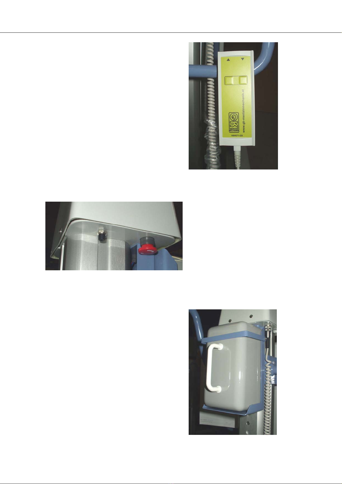
To do this, grasp the battery box by the handle, remove it from
the bracket on the lifter by tilting it slightly to the rear, and
insert it in the bracket of the charger.
Make sure that the battery box engages properly in the socket and
lay the safety strap across the battery. As soon as the mains
power supply is connected, the green LED at the charger lights to
indicate that power is being supplied to the charger. The red LED
lights as long as charging current is flowing. If the charging
current drops below 40mA during the charging process, the red LED
is extinguished to indicate that the battery is fully charged. The
charging period lasts at least 12 hours. The battery can be re-
charged at any time.
After charging, remove the plug from mains power supply.
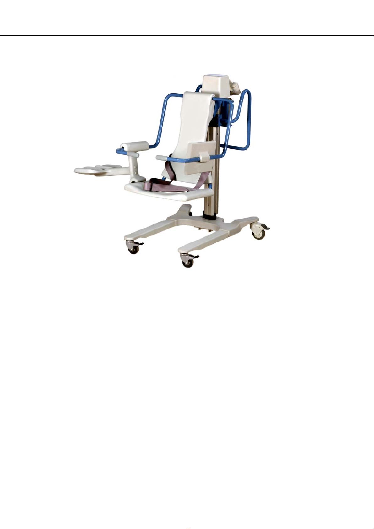
The red emergency off mushroom button serves down the lifter
drive.
Pressing the mushroom button brings the switch into the off posi-
tion and fixes it there mechanically. Turning the button clockwise
releases the locking mechanism and the switch turns the drive back
on again. In order to avoid a panic situation with the patient in
the raised position, the small black button can be pressed in or-
der to lower the lifter. This function is only available while the
emergency off button is in the operating position.
Note: The motor and gearing are lubricated for life and re-
quire no maintenance. The lifter column is lightly
greased to allow friction-free operation.
The electrical lifter controller switches off if:
1. There is an overload of more than 1500N.
2. The battery state of charge is very low (yellow LED
lights).
3. Resistance is felt while the lifter is being lowered.

8
Safety instructions
■Safety instructions:
Please make sure that...
...the lifter is always operated by trained personnel who fol-
low the instruction given in the Operating Manual.
...the lifter is cleaned thoroughly after every use.
It is recommended that the lifter is examined for visible damage
at regular intervals (regardless of how often it is used). We also
recommend that you ask our service Department to carry out a
safety and functional check at least once every year.
Note: The safety rules and instructions in this operating ma-
nual must be observed in order to ensure safe and proper
use of the equipment. Adjustments and repairs must be
carried out by authorized and appropriately qualified
persons. All claims under guarantee become void if these
requirements are not met.

Service
9
■Service
Lifter cannot be moved upwards or downwards:
? Emergency off button is engaged.
►Unlock by turning the button in a clockwise direction.
? Battery discharged – yellow LED lights.
►Charge the battery.
? Battery box not connected to plug.
►Connect to plug.
Lifter cannot be moved downwards without applying force:
? Pinching protection has been triggered.
►Gently push the Lifter downwards.
No movement is possible although the battery is fully charged:
? Defect fuse.
►Unscrew the cap and check the fuse on the electronic. Also
check the fuse in the battery box.
Note: These tasks must be performed only by trained and
authorized personnel.
?malfunction cause
►what to do

Technical data
10
■Technical data
For the Patient lifter — seat type “Hektor”
- Lifting Power 1500N
- Own weight 650N
- Lifting height 630mm
- Lifting speed 20mm/sec.
- Electrical power lead accumulator, gas-tight
12V, 7.2Ah
Battery fuse 20Atr
Overload protection at 14A
Loading time 12 hours
- „On“ period 1 Min. / Pause 10 Min.
- Tested in accordance with EN 60601-1 und Nr. 93/42 EWG
- Degree of protection IP 24
- Protection against
electric shock Typ B
- Transport and storage - 20°C at + 40°C
- Operating temperature + 10°C at + 40°C
- Dimensions 116 x 68 x 95 (HxBxT) cm
- EMC tested in accordance with EN 60 601-1-2
- Charger Type DL 12/1
- Power supply voltage 230V, 50Hz
- Charging power 13.6V, 1A
- Protection class II
- Loading characteristic IU
- Protection against ingress
of moisture IP 20
- Tested in accordance with EN 60 335 / 2-29
Disposal of the lifter at the end of its lifetime:
Metals Iron galvanized coated,
aluminium anodized, copper
with PVC, high-grade steel
Plastic Epoxy with glass-fibre,
polyurethane
Battery Lead with gel-type electrolyte
(sulphuric acid)
Table of contents