POLI-TAPE Clam Press Service manual

operators handbook
Model PT-05
Model PT-06

Preface
Dear User
Welcome to the growing group of PT-06 Clam-Press and PT-05 Clam-
Press Mini users. The product you have purchased has been carefully
designed and manufactured to ensure that you, the user, will gain the
maximum benefit.
All POLI-TAPE products are specifically designed to ensure ease of
use with particular attention to safety requirements.
Should you discover any fault or damage upon receipt of this product,
you should immediately contact your supplier.

Contents
1. Introduction PT-06 Clam-Press and PT-
05 Clam-Press Mini
1
1.1 Specifications of the PT-06 Clam-Press and PT-05
Clam-Press Mini 1
1.2 Safety 2
2. Installation 4
2.1 Transport instructions 4
2.2 Installing the machine 4
2.3 Electrical requirements 4
2.4 Adjusting the pressure 5
3. How to operate the PT-06 Clam-Press
and PT-05 Clam-Press Mini
6
3.1 Starting with the PT-05 Clam-Press Mini and PT-06
Clam-Press 6
3.2 Working with heat transfer materials 6
3.3 Pressing pad assembly 7
3.4 Shutting down the machine 7
4. Maintenance of the Machine 8
4.1 Daily maintenance 8
4.2 Periodic maintenance 8
4.3 Cleaning 8
5. Machine Drawings and Diagrams 9
5.1 General Layout 10
5.2 Exploded diagram and parts list - PT-06 Clam-Press 11
5.3 Exploded diagram and parts list - PT-05 Clam-Press
Mini 12
5.4 Control Unit operation 13
6. Design Change 14
7. Guarantee (Limited Warranty) 15
Declaration of Conformity 16

Page 1
1. Introduction PT-06 Clam-
Press and PT-05 Clam-Press
Mini
1.1 Specifications of the PT-06 Clam-Press and PT-
05 Clam-Press Mini
The PT-06 Clam-Press and PT-05 Clam-Press Mini are manually
operated heat presses for transfer printing and material fusing. They
are ideal for medium volume production.
The work areas are:
PT-06 Clam-Press 38 x 38 cms (15 x 15 ins) and PT-05 Clam-Press
Mini 28 x 38 cms (11 x 15 ins).
Specifications European Machine
PT-06 Clam-Press PT-05 Clam-Press
Mini
Power consumption 2200 Watts 1750 Watts
Power supply 230 Volts AC 230 Volts AC
Max. working temperature 260oC260
oC
Machine height open 86 cms 86 cms
Machine height closed 34.5 cms 34.5 cms
Machine width 38 cms 28 cms
Machine depth 61 cms 61 cms
Net weight 31 kg 27 kg
Press pad dimensions 38 x 38 cms 28 x 38 cms
Auxiliary Fuses 2 A 2 A

Page 2
1.2 Safety Tips
iIf required, our customer service team can arrange
maintenance service.
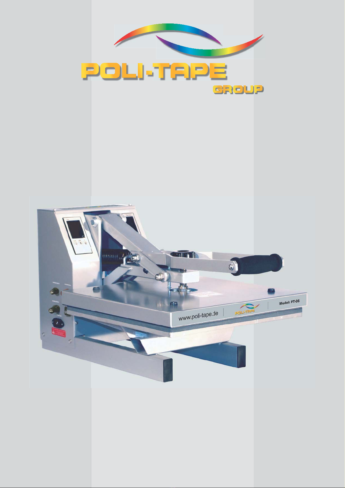
iThe PT-06 Clam-Press and PT-05 Clam-Press Mini
meet the European Legislation standard. Under normal
conditions accidents are rare. However listed below are
some practical points to ensure your safety.
x Always use both hands when opening or closing the
press for positive control of the movement of the
handle.
x Always switch off the current (and pull plug out of the
socket) when undertaking maintenance work or when
cleaning the machine.
x Ensure that there is sufficient space around the
machine. Cables and connections must not get
jammed. Although the heat radiation of the press is
low, there should be enough space for cooling down.
x Avoid contact with the heat plate.
iDO NOT REMOVE THE INSTRUMENT COVER
UNLESS QUALIFIED TO DO SO - touching internal
parts is dangerous and may cause shock hazard. All
electrical connections inside covers are live. Never operate
Press with any covers and/or guards removed.
iPROTECT THE MAINS CABLE - damage to the mains
cable may cause fire or shock hazard. When unplugging,
hold by the plug only and remove carefully. Take care that
the mains cable does not come into contact with the heat
plate (or moving parts of the mechanism) during operation
of the machine.
iOPERATING AMBIENT TEMPERATURE RANGE -
the operating ambient temperature range is 32oF - 104oF, (0
- 35oC) and humidity of 20 - 80%.
iMACHINE FUSES - type: ultra rapid (FF) fuses 1¼” 240 Vac
max. 15 amps. (110 Vac max. 15 amps) for the PT-06 Clam-
Press 240 Vac max. 10 amps. (110 Vac max. 10 amps) for the
PT-05 Clam-Press Mini.
iWARNING - THIS APPARATUS MUST BE
EARTHED (GROUNDED)

Page 3
Safety Tips (cont.)
iCAUTION
This machine gets hot whilst operating. Take care
not to touch any surfaces that are labelled “Caution
this plate is HOT”.
iMACHINE OPERATION
Only persons trained to do so should operate this machine.

Page 4
2. Installation
2.1 Transport instructions
The machine comes to you either shrink-wrapped or in a box. If you
have to transport the machine at any time it is recommended that you
use a similar box and packing method. Please let the machine cool
down and lower the handle to the locked position.
2.2 Installing the machine
2.2.1 Remove all packaging from the heat press.
2.2.2 Check to ensure that no damage has been caused to the
machine during transit.
2.2.3 Place the machine on a sturdy horizontal surface that is within
easy reach of the operator and allow space for the handle to
move up to the loading position. Ensure that no items
vulnerable to heat radiation are too close to the machine.
2.3 Electrical requirements
The PT-06 Clam-Press and PT-05 Clam-Press Mini should be
connected to the mains supply, (nominally 230V AC for the European
Market or 110V AC for America) by the mains cable provided and a
suitable plug.
The presses are designed for 230 volts AC 50/60 hertz and require
exclusive use of a power outlet rated for at least 15 amps for PT-06
Clam-Press and 10 amps for PT-05 Clam-Press Mini.
Ensure that the supply rating on the machine specification plate
corresponds with your local supply and that the correct plug is fitted.
MAINS LEAD
The wires in this mains lead are coloured in accordance with the
following code:
Green and Yellow:EARTH
Blue: NEUTRAL
Brown: LIVE
As the colours of the wires in the mains lead of this apparatus may not
correspond with the coloured markings identifying the terminals in your
plug, proceed as follows:-

Page 5
1. The wire coloured green and yellow must be connected to the
terminal in the plug that is marked by the letter E, or by the
safety earth symbol coloured green, or green and yellow.
2. The wire coloured blue must be connected to the terminal,
which is marked with the letter N.
3. The wire coloured brown must be connected to the terminal,
which is marked with the letter L.
4. NOTE:
Replacement of the mains cable must be done by a competent
service engineer.
HEATING ELEMENT
The heating element fitted to the PT-06 Clam-Press is rated at 2200
Watts and the element for the PT-05 Clam-Press Mini is rated at 1750
Watts.
Never connect to any outlet or power supply having a different
voltage/frequency from that on the machine data plate.
2.4 Adjusting the pressure
This press is fitted with a pressure-adjusting unit, which enables the
heat plate assembly to be raised or lowered by use of a pressure
adjustment knob located on the top of the heat plate:
a) To increase pressure or to use thinner materials turn knob
clockwise.
b) To decrease pressure or to raise the heat plate assembly to
enable thicker materials to be used, turn the adjustment knob
anticlockwise.
NOTE
DO NOT adjust the pressure when the machine is clamped shut
CAUTION
This machine is designed to be used with a light to medium
clamping pressure. If the pressure of the machine is adjusted too
high this may cause damage to the machine and invalidate your
warranty. Other machines are available for high-pressure
applications. Please ask your supplier for details.

Page 6
3. How to Operate the PT-06
Clam-Press and PT-05 Clam-
Press Mini
3.1 Starting with the PT-06 Clam-Press and PT-05
Clam-Press Mini
3.1.1 Plug into your supply outlet and switch supply on.
N.B. Please ensure the mains plug is easily accessible to the
operator so that in the event of a fault the machine can be
unplugged.
3.1.2 Turn on the PT-06 Clam-Press and PT-05 Clam-Press
Mini; the on/off switch is on the side of the machine. Set the
machine controls as necessary. See instructions for adjusting
the pressure, page 5 and operation of Control Units page 13.
Press red on/off button to activate and heat the Heat Plate.
3.2 Working with Heat Transfer Materials
Always ascertain from the supplier of material and transfer paper, that
the material to be used is suitable for, and has been prepared for transfer
printing.
3.2.1 Close the press to check the amount of closing pressure the
machine has been set at. If more or less pressure is required
then open the machine and turn the pressure-adjusting knob
located on top of the heat plate. For further instructions see
“pressure adjustment”.
3.2.2 Ensure that the heat controller is set to the correct setting for
the material being used. Before using the machine, preheat the
base pad of the machine by closing and re-opening the press a
number of times.
After pre-heating ensure that the machine is in the fully open
position.
3.2.3 Place the article to be transfer printed onto the pressing pad
and locate the transfer paper/substrate material on top in the
position required. Take care not to touch the heat plate to
avoid the risk of a burn.
3.2.4 Lower the heat plate by pulling down the handle.

Page 7
3.2.5 When the required time interval has elapsed the alarm will
sound and the press should be opened by lifting the handle up
until it locks into position.
Unload the garment from the table of the machine taking
care not to touch the heat plate to avoid risk of a burn.
3.3 Pressing Pad Assembly
The pressing pad normally supplied with this machine is silicone
rubber. The pressing pad must be maintained in good condition at all
times and replaced when showing signs of wear. A worn pressing pad
will always affect the quality of printing/fusing. Do not insert items
into the machine, which would tend to cut the pressing pad, i.e. buttons,
pins, press-studs or zips.
Never allow the hot heat plate to rest on the pressing pad when the
press is not being used as the pad may be damaged.
IMPORTANT NOTE:
The pressing pad supplied with the machine is of the correct thickness.
Using a thicker pad may invalidate your warranty.
3.4 Shutting Down the Machine
To shut down the machine, turn off the on/off switch at the side of the
machine. The handle should be in the up position.

Page 8
4. Maintenance of the Machine
4.1 Daily Maintenance
For good press results it is important to keep the press surfaces clean.
Wipe the surface of the heat plate with a dry cloth before use when the
plate is cold.
4.2 Periodic Maintenance
Put a few drops of oil onto the various pivot pins and the pressure
adjusting screw every three months.
4.3 Cleaning
Clean the outside of the machine frequently with a clean, moist cloth.
This may conveniently be carried out before starting when the machine
is cool. First unplug the machine!

Page 9
5. Machine Drawings and
Diagrams
On the following pages are the schematic diagrams for the PT-06
Clam-Press and PT-05 Clam-Press Mini.
5.1 General Layout……………………………... Page 10
5.2 Exploded diagram and parts list
PT-06 Clam-Press…………………………... Page 11
5.3 Exploded diagram and parts list
PT-05 Clam-Press Mini……………………. Page 12
5.4 Control Unit operation…………………….. Page 13

www.poli-tape.de
Model: PT-05
5.1 Machine General Layout
MACHINE
OPERATING
HANDLE
TIME AND TEMPERATURE
CONTROLLERS
PRESSURE
ADJUSTING
KNOB
PAD
TABLE
HEAT PLATE
ON/OFF
SWITCH
Page 10

5.2 Exploded Diagram and Parts List
(PT-06 Clam-Press - 38cmx38cm Heat Plate)
1233
3
4
22
5
6
7
34
35
8
9
10
11
25
24
25
12
26
13
15
18
32
19
20
21
29
14
13
27
12
23
16
17
36
37
28
30a
30
38
Page 11
www.poli-tape.de
Model: PT-06
No.
Description
Qty.
Part No.
1 Pedestal Frame 1 ASCL 1
2 Right Body Box 1 ASCL 2
3 Left Body Box 1 ASCL 3
4 Line Board 1 ASCL 4
5 Fix Action Board 1 ASCL 5
6 Back Cover Board 1 ASCL 6
7 Timer 2 ASCL 7
8 Pressure Adjust Knob 1 ASCL 8
9 Screw 1 ASCL 9
10 Nut 1 ASCL 10
11 Operating Handle 1 ASCL 11
12 Grooved Axle Pins 2 ASCL 12
13 Threaded Axle Pins 2 ASCL 13
14 Handle Links 2 ASCL 14
15 Handle Grip 1 ASCL 15
16 Stay Bar Arm 1 ASCL 16
17 Magnetic Switch 1 ASCL 17
18 Insulation Cover 1 ASCL 18
19 Heater (2.2 Kw) 1 ASCL 19
20 Silicone Pad 1
ASCL 20/38
21 Mother Table 1
ASCL 21/38
22 Temp Controller 1 ASCL 22
23 Axle End Cap Washer 2 ASCL 23
24 Axle End Cap Washer 2 ASCL 24
25 Circlip 2 ASCL 25
26 Pressure Springs 2 ASCL 26
27 Probe 1 ASCL 27
28 3 Pin Socket 1 ASCL 28
29 On/Off Switch 1 ASCL 29
30 Auxiliary Fuse Holder 1 ASCL 30
30a
Auxiliary Fuse 1 ASCL 30A
31 2 Amp Auxiliary Fuse 1 ASCL 31
32 Insulation Cover Rubbers 4 ASCL 32
33 Main Control Unit 1 ASCL 33
34 Solid State Relay 1 ASCL 34
35 Heat Sink 1 ASCL 35
36 Main Fuse Holder 1 ASCL 36
37 15 A Mains Fuse 1 ASCL 37
38 Mains Indicator Light 1 ASCL 38

33
12
3
4
22
5
6
7
8
9
10
11
25
24
25
12
26
13
15
18
32
19
20
21
29
14
13
27
12
23
16
17
28
34
35
5.3 Exploded Diagram and Parts List
(PT-05 Clam-Press Mini - 28cmx38cm Heat Plate)
Page 12
www.poli-tape.de
Model: PT-05
36
37
30a
30
38
No.
Description
Qty.
Part No.
1 Pedestal Frame 1 ASCL 1
2 Right Body Box 1 ASCL 2
3 Left Body Box 1 ASCL 3
4 Line Board 1 ASCL 4
5 Fix Action Board 1 ASCL 5
6 Back Cover Board 1 ASCL 6
7 Timer 2 ASCL 7
8 Pressure Adjust Knob 1 ASCL 8
9 Screw 1 ASCL 9
10 Nut 1 ASCL 10
11 Operating Handle 1 ASCL 11
12 Grooved Axle Pins 2 ASCL 12
13 Threaded Axle Pins 2 ASCL 13
14 Handle Links 2 ASCL 14
15 Handle Grip 1 ASCL 15
16 Stay Bar Arm 1 ASCL 16
17 Magnetic Switch 1 ASCL 17
18 Insulation Cover 1 ASCL 18
19 Heater (1.75 Kw) 1 ASCL 19A
20 Silicone Pad 1
ASCL 20/28
21 Mother Table 1
ASCL 21/28
22 Temp Controller 1 ASCL 22
23 Axle End Cap Washer 2 ASCL 23
24 Axle End Cap Washer 2 ASCL 24
25 Circlip 2 ASCL 25
26 Pressure Springs 2 ASCL 26
27 Probe 1 ASCL 27
28 3 Pin Socket 1 ASCL 28
29 On/Off Switch 1 ASCL 29
30 Auxiliary Fuse Holder 1 ASCL 30
30a
Auxiliary Fuse 1 ASCL 30A
31 2 Amp Auxiliary Fuse 1 ASCL 31
32 Insulation Cover Rubbers 4 ASCL 32
33 Main Control Unit 1 ASCL 33
34 Solid State Relay 1 ASCL 34
35 Heat Sink 1 ASCL 35
36 Main Fuse Holder 1 ASCL 36
37 10 A Mains Fuse 1 ASCL 37A
38 Mains Indicator Light 1 ASCL 38

MODE DOWN UP
H
O
L
D
S
T
OP
PV
°
C
S
V
COUNTER
MODE DOWN UP
HOL
D
S
TO
P
PV
°
C
SV
COUNTER
Page 13
Setting Temperature
1. Switch on machine
2. Press 'UP' and 'DOWN' buttons to change
temperature values
3. The unit stores automatically once required
value is achieved
4. Press 'START/STOP' button to start machine
heating
Setting Digital Counter to Zero
1. Press 'CLEAR' button and 'COR' will appear in controller window and 'COUNTER'
value will flash
2. Press 'CLEAR' button again to zero counter
Setting Time
1. Switch on machine
2. Press 'UP' and 'DOWN' buttons to change
time values
3. The unit stores automatically once required
value is achieved
4. Press 'START/STOP' button to start machine
5.4 Operation Of Control Units, Setting Temperature and Time
(The press must always be in the open position before the controller is set)

Page 14
6. Design Change
With the policy of constant improvement and/or modification to meet
changing conditions, the right is reserved to change the design and/or
specifications at any time without prior notification, and therefore
specifications may vary and not be in accordance with this manual.

Page 15
7. Guarantee (Limited Warranty)
POLI-TAPE Klebefolien GmbH warrants that the press is free from
defects in material and workmanship for a period of 12 months from the
date of supply to the customer. The machine comes with a one year
warranty on parts and 90 days labour.
This warranty covers all parts to repair the defects, except when
damage results from misuse or abuse, accident, alteration or negligence
or when a machine has been improperly installed.
If a press covered by warranty should need to be returned to the
factory for examination and repair, if on-site component replacement is
not possible, POLI-TAPE Klebefolien GmbH will make every effort to
repair the customers press. The warranty will only be effective when
POLI-TAPE Klebefolien GmbH authorises the original purchaser to
return the machine to the factory and only when the product upon
examination has proven to be defective.
Should in our opinion any part of this press be defective in materials or
workmanship, it will be replaced or repaired free of charge, provided
that the press has been installed and operated in the correct manner and
not subjected to misuse. If POLI-TAPE Klebefolien GmbH authorise a
replacement press, the warranty of the replacement press shall expire on
the anniversary date of the original machines invoice to the customer.
In order for this warranty to be effective, no return of machine or
parts may be made without prior factory authorisation. (This will
exclude any travelling and/or carriage costs which will be charged at
our discretion).
This is the sole warranty given by the company; there are no
warranties, which extend beyond the description on the face hereof. The
seller disclaims any implied warranty of merchantability and/or any
implied warranty of fitness for a particular purpose; the buyer agrees
that the goods are sold “as is”. POLI-TAPE Klebefolien GmbH does not
warrant that the functions of the press will meet the customer’s
requirements or expectations. The entire risk as to use, quality and
performance of the press lies with the customer. (No claim of any kind
shall be greater than the sale price of the product or part to which the
claim is made).
In no event will POLI-TAPE Klebefolien GmbH be liable for any
injury, loss or damage, including loss of profits, destruction of goods or
any special, incidental, consequential or indirect damages arising from
the use of the press or accompanying materials. This limitation will
apply even if POLI-TAPE Klebefolien GmbH or its authorised agent
had been advised of the possibility of such damage.

A. ADKINS & SONS LIMITED
DECLARATION OF CONFORMITY
on behalf of
POLI-TAPE KLEBEFOLIEN GmbH.
Application of Council Directives:
Standards to which Conformity is
Declared:
Manufacturer's Name: A. Adkins & Sons Limited
Manufacturer's Address: High Cross, 18 Lancaster Road,
Hinckley, Leicester, LE10 0AW, United Kingdom.
Type of Equipment: Machine Range:
PT-02 Mug Press, PT-05 Clam-Press Mini, PT-06 Clam-Press,
PT-11Cap-Press, PT-14 Cap-Pocket Press,
PT-15Swing-Head Press, PT-16 Auto-Clam Press,
PT-20Pneumatic Press, PT-21 Twin-Table Press.
Model Number: .....................................................................
Serial Number: .....................................................................
Year of Manufacture: .....................................................................
I, the undersigned, hereby declare that the equipment specified above conforms to the above
Directives and Standards.
Place: Hinckley, United Kingdom Signature: ..............................................
Date: .................................. Full Name: Marie McMahon
Position: General Manager
www.poli-tape.de
Page 16
Machinery, Low Votage. E.M.C.
BS EN ISO 12100-1:2003+A1:2009
- Safety of machinery: Basic Technology.
BS EN ISO 12100-2:2003 - Safety of machinery: Principles of Design.
BS EN 60204-1:2006
- Safety of machinery: Electrical Equipment of Machines.
BS EN 60529:1992 - Degrees of protection provided by enclosures.
BS EN ISO 13850:2008 - Safety of machinery: Emergency Stops.
BS EN ISO 141211:2007
- Safety of machinery: Principles for Risk Assessment.
BS EN 55011:1998 - Class A Group 2 equipment - EMC Emissions.
BS EN ISO 61000-6-4:2007 - EMC Conducted Emissions.
BS EN ISO 61000-6-2:2005 - EMC Immunity.
This manual suits for next models
3
Table of contents
Popular Power Tools manuals by other brands

Skil
Skil 2230 Original instructions

Makita
Makita TM3000CX7 instruction manual

Hitachi
Hitachi F C J 65V Handling instructions

Chicago Electric
Chicago Electric 35 LB Owner's manual and safety instructions

Georges Renault
Georges Renault KC9035-7 instruction manual

NovoPress
NovoPress ACO403 BT operating manual