POLITEC s.r.l. | Manuale MANA IR SMA –Ver. 2.5
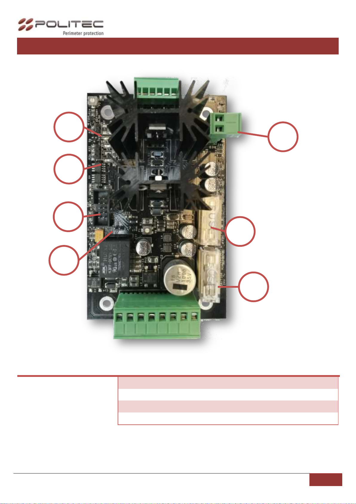
POWER SUPPLY CABLE (PS01B)
CONNECTION TO TERMINAL BLOCK (MES9C)
CONNECTION AND SETTING HEATERS
SERIAL CONNECTION TO THE ADEBUS
Connection to serial port for each column
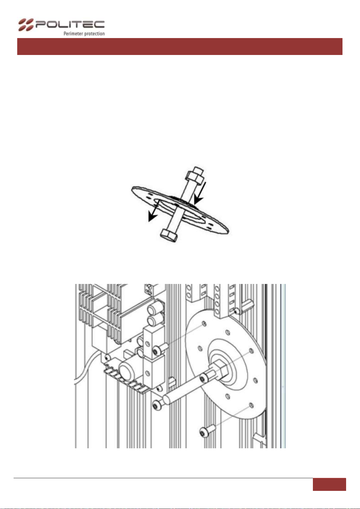
CALIBRATION THROUGH SMA SYSTEM
CALIBRATION WITH PARALLEL BEAMS
CALIBRATION WITH CROSSED BEAMS
SETTING AND PROGRAMMING MOTHER BOARD (MES 9012)
CHARACTERISTICS AND DIP SWITCHES SET
TECHNICAL CHARACTERISTICS
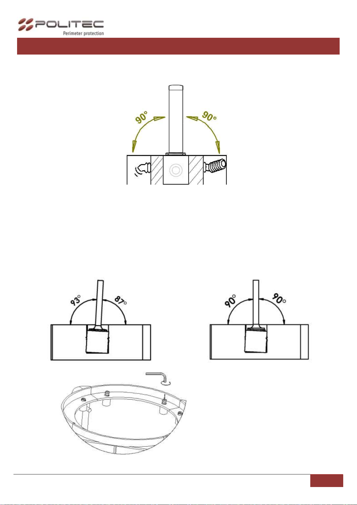
Installation recommendation
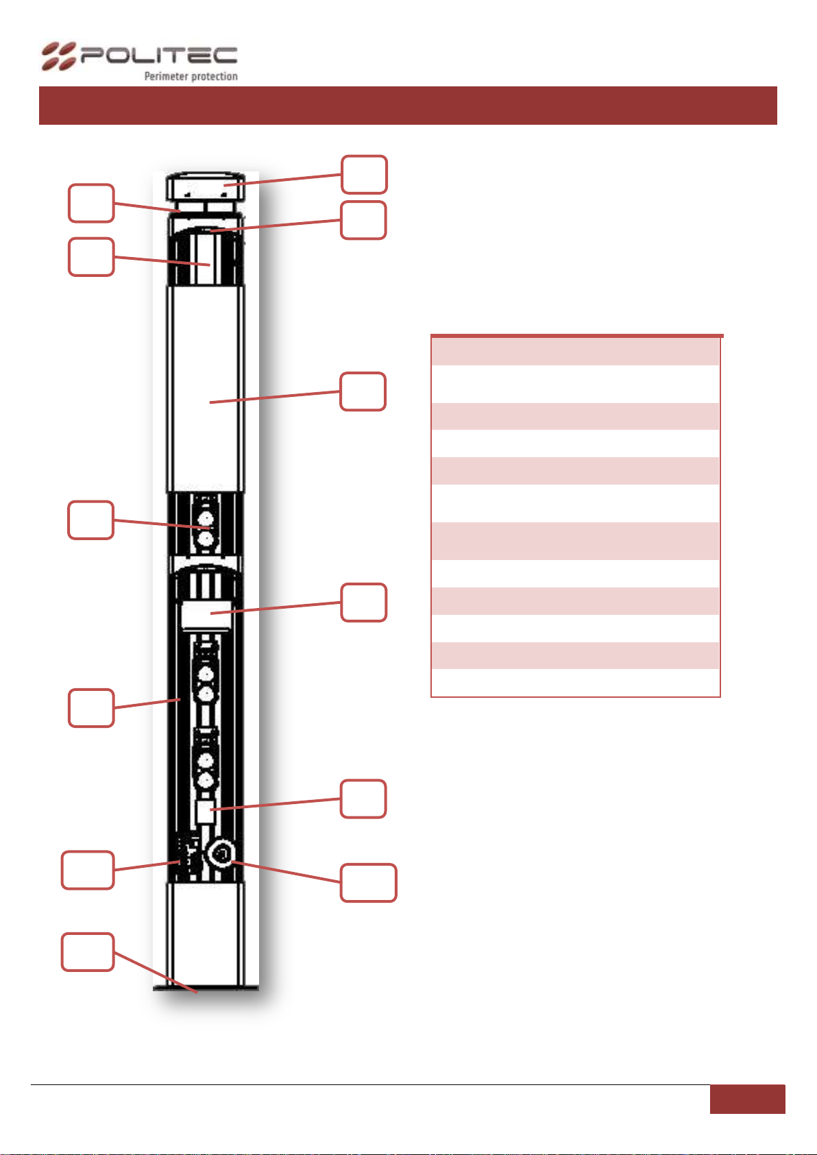
Verify that the beam tower is fully watertight once the cover and end caps have been correctly filled at the
end of the installation.
Use the cable glands supplied on the tower for all cabling must pass through the lower end cap using the
cable glands supplied. The missed used of proper accessories decrease the IP grade protection of the
tower.
Avoid any type of obstruction between the transmitter and receiver.
Avoid installing the receivers beams in a position where direct sunlight, at the same angle as the receivers
beams, can enter directly into optics especially at sunset and sunrise
Do not install multiple beams where the transmitter beam can interfere with other receiver beams. It is
always better place either transmitter or receivers back to back.