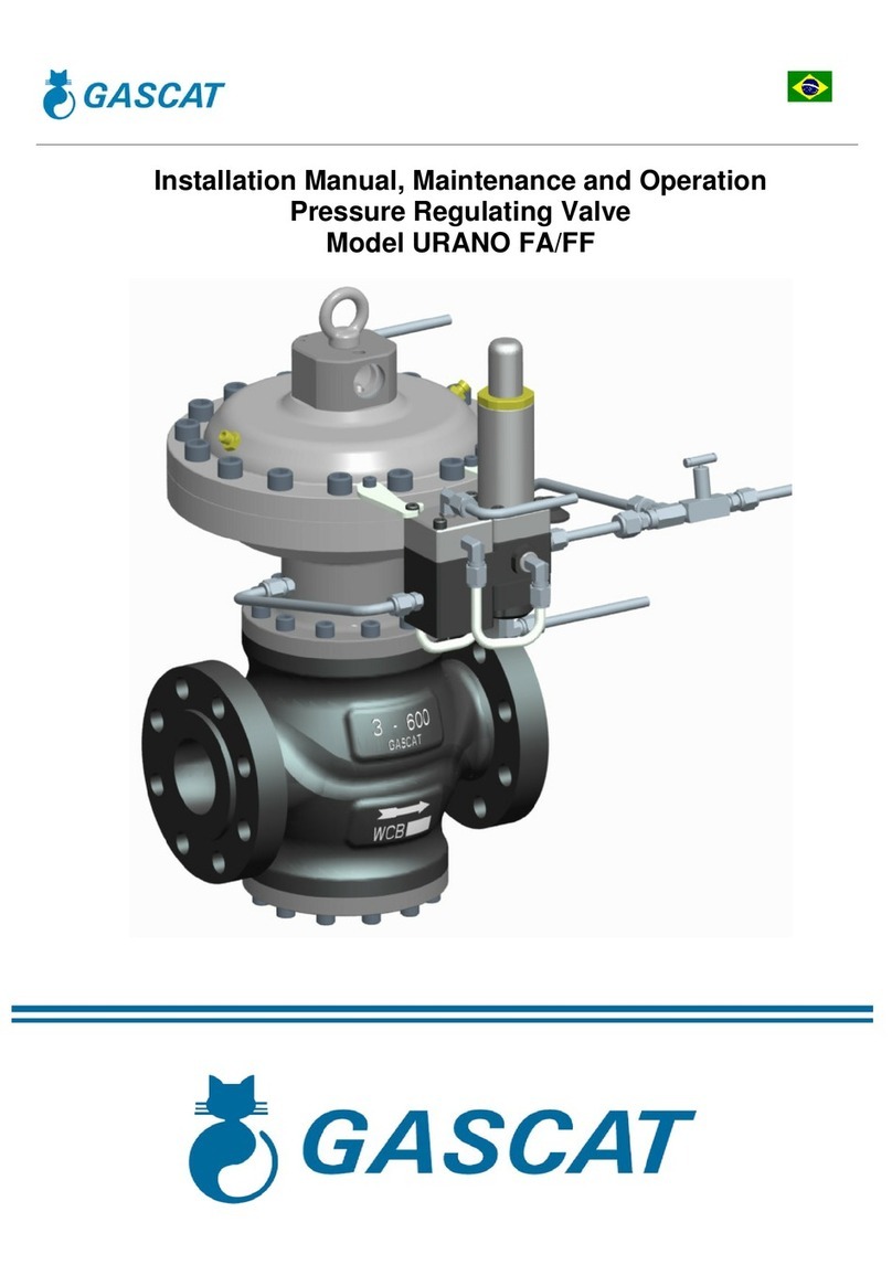
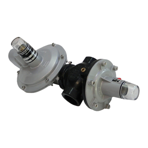
Gascat ARGOS WA User manual

INSTALLATION & OPERATION MANUAL
PRESSURE REGULATOR VALVE
MODEL ARGOS WA

Installation and Operation Manual
Argos WA - Pressure Regulating Valve MI-44
Elaborado Verificado / Aprovado CSQ Data Revisão Página
JJ
GN JM 03/09/18 01 2 de 20
INDEX
1 – INSTRUCTIONS PRIOR TO COMMISSIONING ........................................................................ 3
1.1 – SAFETY AND HEALTH ........................................................................................................ 3
1.1.1 – NOISE ............................................................................................................................ 3
1.1.2 – INSTALLATION .............................................................................................................. 4
1.1.3 – OPERATION .................................................................................................................. 4
1.1.4 – MAINTENANCE ............................................................................................................. 4
2 – INTRODUCTION ........................................................................................................................ 5
2.1 – SCOPE OF MANUAL ........................................................................................................... 5
2.2 – DESCRIPTION ..................................................................................................................... 5
2.3 – SPECIFICATIONS ................................................................................................................ 5
2.3.1 – AVAILABLE CONFIGURATIONS ................................................................................... 5
2.3.2 – AVAILABLE CONNECTIONS ........................................................................................ 6
2.3.3 – TEMPERATURE LIMITS ................................................................................................ 6
2.3.4 – FLOW COEFICIENT ...................................................................................................... 6
2.3.5 – VALVE WEIGHT ............................................................................................................ 6
2.3.6 – PRESSURE REGULATOR SPRING RANGE (SET-POINT) ......................................... 7
2.3.7 – ACCURACY AND LOCK UP .......................................................................................... 7
2.3.8 – PRESSURE REGULATOR DIMENSIONS ..................................................................... 8
3 – OPERATING PRINCIPLE ........................................................................................................... 9
3.1 – THE REGULATOR ............................................................................................................... 9
3.2 – REGULATOR - ACTIVE / MONITOR SYSTEM .................................................................... 9
3.3 – PILOT ................................................................................................................................. 11
4 – INSTALLATION ........................................................................................................................ 11
4.1 – CHECKING SYSTEM INTEGRITY ..................................................................................... 11
4.2 – FILTER ............................................................................................................................... 12
4.3 – CLEANING ......................................................................................................................... 12
4.4 – OTHER IMPORTANT DEVICES FOR A SAFETY INSTALLATION ................................... 12
5 – OPERATION (START UP) ........................................................................................................ 14
5.1 – PRESSURE REGULATOR ADJUSTMENT ........................................................................ 15
5.2 – BACK UP LINE ADJUSTMENT (IS APPLICABLE) ............................................................ 15
5.2 – RECOMMENDED TOOLS FOR START-UP ...................................................................... 15
6 – TROUBLESHOOTING .............................................................................................................. 16
7 – WARRANTY ............................................................................................................................. 16
8 – STORAGE ................................................................................................................................ 17
9 – GENERAL RECOMMENDATION ............................................................................................. 17
10 – COMPONENTS & SPARE PARTS ......................................................................................... 17

Installation and Operation Manual
Argos WA - Pressure Regulating Valve MI-44
Elaborado Verificado / Aprovado CSQ Data Revisão Página
JJ
GN JM 03/09/18 01 3 de 20
1 – INSTRUCTIONS PRIOR TO COMMISSIONING
It should be clearly understood that the information given under the Commissioning Instructions below do not intend to
revoke or substitute instructions laid by any relevant entity and reference should be made to the relevant Standards and/or
existent recommendations on this subject.
It is implied that before Commissioning the performance of the appropriate "Cleaning and Purification Procedures" will
be observed and all the instructions contained in "Pressurization" and "Labor Safety and Health Standards" shall be strictly
attended.
The recommendations of valves' suppliers, as for instance, "open slowly" or "open very slowly" should be strictly
observed.
1.1 – SAFETY AND HEALTH
Regulators, valves, and other pressurized components that contain toxic or flammable gases, or other hazardous
products, are potentially dangerous if not correctly operated and maintained. It is mandatory that all users of these
equipments are properly instructed and warned on their potential danger, and certify yourself that the personnel
responsible for installation, test, commissioning, operation, and maintenance of the plant are skilled enough to perform
their duties. Instruction manuals are provided for orientation of the operators, but it is supposed that they have a basic
knowledge level. If any doubts or ambiguities remain that could affect the proper procedures ask Gascat, which will be
pleased to instruct, or to provide the suitable service or instruction. NOT TO TAKE ANY RISK. Our telephone, fax
numbers, and e-mail are the following:
Gascat Indústria e Comércio Ltda.
Rodovia SP 73, 1141 – Indaiatuba / São Paulo.
CEP 13347-390 – Brazil
Phone: 55 19 3936-9300
Fax: 55 19 3935-6009
E-mail sales@gascat.com.br
The comments below, while not completely inclusive, provide guidance on possible sources of risk to safety and health.
1.1.1 – NOISE
Regulators, valves, and other pressure reducers can produce high noise levels, which can be harmful to persons
exposed to them for long periods of time. Users should assure themselves that appropriate provisions will be taken, in
order to foresee health safety of employees and/or third parties, according to valid standards and recommendations.

Installation and Operation Manual
Argos WA - Pressure Regulating Valve MI-44
Elaborado Verificado / Aprovado CSQ Data Revisão Página
JJ
GN JM 03/09/18 01 4 de 20
1.1.2 – INSTALLATION
All equipment, piping, and vessels are designed to support mechanical efforts, as, for instance, torque and bending
momentum, in addition to internal pressure. However, careful shall be exercised during installation not to develop
excessive efforts, which can cause cracks that may result in serious breakage when the regulator is put into operation.
Excessive tensions can also be caused if the equipment is overburden by piping, which should be otherwise appropriately
supported.
All regulators, shutoff valves, relief valves, etc., shall be installed taking into account the correct flow sense.
Impulse lines are important components of any control system and it is essential for them to be correctly installed
according to instructions.
Impulse lines should be appropriately supported to reduce excessive vibration, which can provoke fatigue breaks. They
should also be positioned so that they cannot serve as feet or hands supports. Impulse lines should be slightly sloping so
that liquids and condensates drain towards the main piping.
Auxiliary systems should not be changed, or modified, without knowledge of the operation conditions and permission of
the responsible in charge.
1.1.3 – OPERATION
Depending on the regulator type, its valve can be positioned fully open. Consequently, when a regulator is put into
operation, the shutoff valves should be open slowly so that the regulator valve can assume its regulating position. If the
valves are quickly opened the upstream pressure can pass downstream through the regulator and over-pressurize
downstream the main line.
All regulators, etc., should operate with the regulating spring specified by the manufacturer. This provision is particularly
important when operating relief or shutoff valves, since incorrect springs can hinder a relief valve to open and a shutoff
valve to close at the proper time.
Provisions should be taken to avoid water input through breathing and ventilation openings.
1.1.4 – MAINTENANCE
Regulators and valves contain gases at pressures that sometimes are higher than the atmospheric pressure. Before
trying to investigate any problem or to perform service maintenance of the equipment, they should be safely de-
pressurized. Besides, as most gases can be flammable, poisonous, corrosive, or somehow, dangerous, it may be
necessary to purge the installation with an inert gas, as nitrogen. Special precautions are necessary for operation with
oxygen or hydrochloric gas and the user should be reassured that appropriate procedures are implemented.
Eventually, it is not enough to isolate the high-pressure device, since high pressures can be retained downstream of
isolation valves. Do not try to remove covers, plugs, etc., before these parts are properly freed-up. Even so, it is advisable
to consider if high-pressure gas can be present at the time of removal of covers and plugs.

Installation and Operation Manual
Argos WA - Pressure Regulating Valve MI-44
Elaborado Verificado / Aprovado CSQ Data Revisão Página
JJ
GN JM 03/09/18 01 5 de 20
Most regulators use spiral springs as the loading device. It is important to reduce the load of these springs relieving
their loaders as much as possible. In some cases, some residual load may last, even though the spring is relaxed to the
limits of its housing.
There is not a recommendation about the frequency to change the repair kit due several different variables in the
process that changes installation by installation as, for example, process gas quality, service conditions etc. The repair kit
should be changed when the regulator has problems during operation, as leakage, increase in set pressure and also
others that become the quality and regulator performance different.
However, Gascat recommends that after all regulators opening during maintenance service the repair kit must be
changed. It is also indicated to change a complete repair kit and not only specific part (example o’ring, obturator), to have
the all spare parts with same life time.
Gascat already inform to avoid all non original and genuine parts.
2 – INTRODUCTION
2.1 – SCOPE OF MANUAL
This Instruction manual has as objective supply information about operation, installation and maintenance about
ARGOS WA pressure regulator manufactured by GASCAT.
2.2 – DESCRIPTION
Argos Axial WA Series is a regulator designed by Gascat’s engineering, that is included into the pilot-operated pressure
regulators family, to be applied with all gases.
This wafer type regulator is developed with face-to-face short what allow an utilization with pressure regulating stations
with few available space for installation; it is also for compact installations with underground stations, saving space and
reducing the costs with boxes and skids.
Because of robust construction, simple, flangeless type, with few components, it also reduce non-programable
maintenance. These qualities result in a repair kit with low price. Additionally, this valve can be supplied with pipe screws
necessary to assemblage in the pipe or skid (it is not included in the standard version – it should be requested).
Easy installation and simple regulation; the restrictor installed near the inlet pilot according to the schemes below
adjusts the loading and unloading pilot velocity allowing the adjustment of this relative response to the set-point achieved
and lock-up pressure.
2.3 – SPECIFICATIONS
2.3.1 – AVAILABLE CONFIGURATIONS
ARGOS WA:
- Single regulator;
- Active / Monitor system;

Installation and Operation Manual
Argos WA - Pressure Regulating Valve MI-44
Elaborado Verificado / Aprovado CSQ Data Revisão Página
JJ
GN JM 03/09/18 01 6 de 20
2.3.2 – AVAILABLE CONNECTIONS
ND FLANGE ASME
B16.5
1” 150#/300#
2” 150#/300#
3” 150#/300#
4” 150#/300#
2.3.3 – TEMPERATURE LIMITS
Operating temperature: -20°C a 60°C
Ambient temperature: -20°C a 60°C
The temperature limits informed at this manual or in any applicable standard must not be exceeded under any
circumstances, at risk of damage the equipment, safety of installation and safety of people involved in the operation.
2.3.4 – FLOW COEFICIENT
DN KG
1” 400
2” 1140
3” 2800
4” 4900
2.3.5 – VALVE WEIGHT (Kg)
DN SINGLE ACTIVE/MONITOR
150# 300# 150# 300#
1” 7 10 13 16
2” 11 14 29 35
3” 21 15 - -
4” 32 38 - -

Installation and Operation Manual
Argos WA - Pressure Regulating Valve MI-44
Elaborado Verificado / Aprovado CSQ Data Revisão Página
JJ
GN JM 03/09/18 01 7 de 20
2.3.6 – PRESSURE REGULATOR SPRING RANGE (SET-POINT)
G-80 PILOT
SPRING COLOR PART NUMBER RANGE
YELLOW / GREY 01.50.09 20 – 50 mbar
BLUE 01.50.10 45 – 100 mbar
WHITE / GREY 01.50.21G 90 – 250 mbar
SILVER 01.50.21P 150– 430 mbar
GREY 01.50.24 340 – 1100 mbar
G-31 PILOT
SPRING COLOR PART NUMBER RANGE
SILVER 01.49.62 0.7 – 2.8 bar
GREEN 01.49.65 2.0 – 5.5 bar
RED 01.49.64 4.5 – 14.0 bar
BROWN 01.49.65 4.0 – 18.3 bar
BLACK 01.49.65 14.7 – 32.0 bar
2.3.7 – ACCURACY AND LOCK UP
Pressure regulator: AC up to 2,5% / SG up to 5%
SSV: AG up to 5

Installation and Operation Manual
Argos WA - Pressure Regulating Valve MI-44
Elaborado Verificado / Aprovado CSQ Data Revisão Página
JJ
GN JM 03/09/18 01 8 de 20
2.3.8 – PRESSURE REGULATOR DIMENSIONS

Installation and Operation Manual
Argos WA - Pressure Regulating Valve MI-44
Elaborado Verificado / Aprovado CSQ Data Revisão Página
JJ
GN JM 03/09/18 01 9 de 20
3 – OPERATING PRINCIPLE
3.1 – THE REGULATOR
The pressure regulator Argos works by principle of drop pressure in the upper chamber (diaphragm of main valve).
In the flow absence the pressure regulator stays close, because the pressure in the upper chamber of diaphragm (feed by
the pilot), added to the spring force is superior to the pressure that acts below the diaphragm (inlet pressure).
The pilot, in this condition of flow absence, stays closed, because the outlet pressure added to obturator spring of pilot is
superior to the regulating spring force, and moves the obturator set upward, against the pilot seat, closing the pilot gas
passage.
In case of flow, the pressure in the sensing line start decreasing, causing the pilot opening because of the regulating spring
of pilot added to the pressure under its diaphragm. In parallel, the discharge pressure also decreases. In this condition,
occur the reducing of the pressure in the upper chamber of diaphragm of main valve. Then, the inlet pressure become
superior to the spring force of main valve added to the pressure in the upper chamber of diaphragm of main valve, allowing
that the main valve opens, releasing the gas to the process.
3.2 – REGULATOR – ACTIVE / MONITOR SYSTEM
In the active / monitor system, the regulator working principle is similar then previously explained.

Installation and Operation Manual
Argos WA - Pressure Regulating Valve MI-44
Elaborado Verificado / Aprovado CSQ Data Revisão Página
JJ
GN JM 03/09/18 01 10 de 20
The upstream regulator (monitor) keeps in the open position, because the pilot sensing line monitors the active pressure
regulator set point and, as its set point is lightly higher, the pilot keeps opened. The reason that this pilot stays opened is
due of pressure under its diaphragm that added to the obturator spring that are lower than the regulating spring force that
moves this obturator set downward opening the pilot.
With this, the pressure in the diaphragm upper chamber in the monitor regulator keeps lightly lower than the inlet pressure
allowing the valve stays in the open position during normal process service conditions.
In case of active regulator fail that results in increase in outlet pressure, the pilot of monitor regulator start closing up to
achieve the set point of this pilot, and then the monitor regulator can assume the control of pressure reduction in the
system. From this moment, the working principle of this valve is similar then the active regulator.
The configuration of assemblage active / monitor is highly utilized in the gas distribution and transmission. This
configuration is normally adopted when the difference between the inlet and outlet pressure is over than 16 bar and the
strength pressure test in the pipe and other components upstream the regulator is inferior than the inlet pressure as

Installation and Operation Manual
Argos WA - Pressure Regulating Valve MI-44
Elaborado Verificado / Aprovado CSQ Data Revisão Página
JJ
GN JM 03/09/18 01 11 de 20
specified, for example in the standard DIN EN 12186, in this case the objective of use of monitor regulator is to increase
the system safety level.
However, is important to remember that this is a recommendation of DIN EN 12186 and that there are other standards that
specifies different conditions of use of active / monitor system.
The active / monitor system consists of utilization of two pressure regulators in series being one of them called active that
will be in operation (regulating the pressure) under normal process service conditions and one monitor regulator that
should stay totally open under normal process service conditions, and will assume the pressure regulating in case of active
regulator fail.
3.3 – PILOT
The pressure regulator model ARGOS WA manufacture by GASCAT use pilot the G-30 or G-80 model depending
of the desired set-point. If the set-point is greater than 0.7 bar, applies the G-30.
This pilot is responsible by the control of feed pressure of main regulator actuator and by consequence of the pressure
regulator aperture.
4 – INSTALLATION
4.1 – CHECKING SYSTEM INTEGRITY
Before installing the pressure regulator it’s necessary to insure that:
1) The equipment are in perfect conditions or has evidences of damage during the transport, in case of
perceptible damage in the equipment do not proceed with installations and get in contact with GASCAT.
2) The space provided for the acess and installation of equipment is appropriate, including future maintenance.
3) The installation was designed to support the load imposed by the equipment.
G-30 PILOT
G-80 PILOT

Installation and Operation Manual
Argos WA - Pressure Regulating Valve MI-44
Elaborado Verificado / Aprovado CSQ Data Revisão Página
JJ
GN JM 03/09/18 01 12 de 20
4) The inlet and outlet pipe connections are in the same level.
5) All connections for sense line and discharge line requested by the model of pressure regulator are arranged in
the pipeline and respect the dimensions provided by manufacturer.
6) Was arranged pressure indicators at the inlet and outlet of the pressure regulator to insure the correct
adjustment of set point during the commissioning.
7) Was arranged a vent line between the pressure regulator and the first block valve in the outlet of stream to help
the operator during the start-up.
8) Check the flow direction in the valve body and pay attention in the installation to assure that the valve are in the
correct position.
4.2 – FILTER
We recommended the installation of a basket type filter, with minimum 150 mesh, as close as possible to the regulator
input, without being joined flange to flange, because, if the filter is installed immediately upstream of the regulator, it can
produce turbulence that will cause disturbances in the pressure control of the regulator. Care with the filter installation is
essential to the perfect operation of the apparatus, because, particles eventually found in the piping can lodge themselves
the seat and the shutter, damaging them and producing direct flow.
4.3 – CLEANING
Check piping cleaning before the installation of the regulator. We recommended a complete purge of the line with
nitrogen or compressed air.
4.4 – OTHER IMPORTANT DEVICES FOR A SAFETY INSTALLATION
It is recommended for a safety installation:
1. Manual On-Off valve (sphere or similar) 6. Manometer (for outlet pressure)
2. Filter (with drain if possible) 7. Purge valve ND ½’’
3. Manometer (for inlet pressure) 8. Partial Pressure Relief Valve (CH Series)
4. Slam-shut Valve (model GIPS FC) 9. Manual On-Off valve (sphere or similar)
5. Pressure regulator (ARGOS WA)

Installation and Operation Manual
Argos WA - Pressure Regulating Valve MI-44
Elaborado Verificado / Aprovado CSQ Data Revisão Página
JJ
GN JM 03/09/18 01 13 de 20

Installation and Operation Manual
Argos WA - Pressure Regulating Valve MI-44
Elaborado Verificado / Aprovado CSQ Data Revisão Página
JJ
GN JM 03/09/18 01 14 de 20
5 – COMMISSIONING AND START UP
5.1 – PRESSURE REGULATOR ADJUSTMENT
Always, before proceeding with the equipment commissioning it is important to:
1) Check if the equipment is properly installed according to the recommendations of item 4.5 of this manual.
2) Shut the blocking valves of the inlet, output and bypass (if applicable)
3) Open vent valve downstream of the last pressure regulator installed on the span.
4) Make sure that the station is depressurized.
5) Check if all connectors are properly secured in the station before starting pressurization of the span.
6) Check if the installed equipment has suitable operating conditions, using the information available on the
nameplate attached to the equipment.
7) Make sure that the SSV is in the shut position.
ATTENTION:
* Under no circumstances proceed with pressurization of the span where the
equipment is installed by the downstream valve of the equipment.
* Under no circumstances proceed with the depressurization of the span
where the equipment is installed by the valve located upstream of the
equipment, such as the filter drain.
ATTENTION:
GASCAT’s SSV are sent to the field already calibrated, however,
depending on transport conditions and the equipment handling the
valve may have its set point changed.
Therefore, we recommend that you check the SSV set point with the
help of an external air supply directly connected to the actuator,
before proceeding with the pressurization of the span.
The model BRISE PLUS valves are not sent to the field with adjusted
set points; this measure tends to preserve the life of the equipment
internals. Therefore, after receiving a pressure regulator valve model
BRISE PLUS, remember that you must perform the set point
adjustment before putting the equipment into operation.
The pressure reducing station setting shall be in accordance with the DIN EN 12186 / NBR 12712
standards and all other regulations in force in the region where it will operate.

Installation and Operation Manual
Argos WA - Pressure Regulating Valve MI-44
Elaborado Verificado / Aprovado CSQ Data Revisão Página
JJ
GN JM 03/09/18 01 15 de 20
1) Close slowly the on-off manual valve upstream of regulator.
2) Close slowly the on-off manual valve downstream of regulator.
3) Certify that the springs of pre pilot and pilot are totally released.
4) Certify that bleed (discharge valve / needle valve) is open in 1/8 of turn.
5) Open the purge valve installed downstream of regulator 1/8 of turn.
6) Open slowly the on-off manual valve upstream of regulator verifying the gas pressure.
5.1 – PRESSURE REGULATOR ADJUSTMENT
1) Open the purge valve located downstream of the regulator with approximately 20% of passage.
2) Adjust the regulator pressure with the regulator screw located in the pilot’s upper part, under the protection
cover, to the requested operation pressure.
3) Close the purge valve.
4) Check for regulator lockup with the pressure gauge manometer located downstream of the regulator; a stable
pressure indication for, approximately, 3 minutes.
5) Close the purge valve, and then slowly open the gas output blocking valve.
6) Make fine pressure adjustments; if is necessary using the restrictor passage.
Notes:
1 – The lockup pressure active / monitor systems is always the monitor lockup pressure.
2 – In this type of stations, the pressure line adjusment for blocking test, should be obtained through monitor regulator
before, however, it should be increase up to active regulator until this valve opens totally and the monitor regulator assume
the system regulation.
5.2 – BACK UP LINE ADJUSTMENT (IF APPLICABLE)
Isolate the main line depressurizing the system.
Adjust the secondary line pressure as already described with a pressure at the active regulator 10% below the
active regulator pressure of the main line.
5.3 – RECOMMENDED TOOLS FOR START-UP
Combination spanner size: 3/8” and 19 mm
Adjustable spanner 1”

Installation and Operation Manual
Argos WA - Pressure Regulating Valve MI-44
Elaborado Verificado / Aprovado CSQ Data Revisão Página
JJ
GN JM 03/09/18 01 16 de 20
6 – TROUBLE SHOOTING
To maintain the pressure regulator in the correct conditions of operation, the pressure regulators model
ARGOS WA must be submitted to preventive maintenance, the periodicity depends of the flow, quantity/type of
contaminants and the operation conditions.
Defect Probable Cause Solution
Fall of output pressure /
insufficient flow Dirt Filter Check the filter and clean it.
Increase of output pressure
/ direct passage
Particles between seat /
shutter
- Loose the lock screws of the regulator top
cover and remove the lid / pilot assembly from its
body.
- Check the shutter / diaphragm and grid / seat
condition.
- Clean or replace them, if damaged.
Particles between shutter
shaft / pilot seat
Remove the central plug of the pilot cartridge.
Clean or replace the cartridge, if damaged.
Diaphragm rupture Replace the diaphragm.
7 – WARRANTY
We warrant our products, for a 12 months period from the date of invoicing, if the products are in operation, extending
the warrant up to 18 months, in case they are in stock. Such warranty only covers those cases for which the occurrence of
production defects are evidenced, which remained unnoticed at the time the product delivery.
To present warranty is not valid if it is found that the defect or mishap was caused by accident, normal wear,
inadequate installation, improper maneuvering or use, inadequate storage, assembly disregarding technical standards or if
the buyer undertook repairs or changes in equipment by himself, without the manufacturer's previous authorization.
The information contained in this manual contains Gascat's supply conditions, independently of the verified
performance.
The information herein contained shall not be interpreted or suggest performance warranty in relation to the final
products, or the system usage purpose, nor should they serve as usage recommendation for any product or process
mentioned in the specifications. This system should only be operated by qualified technician trained for this purpose; and
no changes that may affects the system safety can be executed without our previous authorization.
GASCAT Ind and Com. Ltda. withhold the right to make changes without notice, introducing improvements in the
described products drawings or specifications.

Installation and Operation Manual
Argos WA - Pressure Regulating Valve MI-44
Elaborado Verificado / Aprovado CSQ Data Revisão Página
JJ
GN JM 03/09/18 01 17 de 20
8 – STORAGE
The regulators should not suffer mechanical shock, not to risk internal components' damages.
The regulators should be stored at a clean and dry place, protected from bad weather
9 – GENERAL RECOMMENDATION
1) We test our regulators and valves at the requested operation conditions.
2) Criteria and maintenance steps are contained in manuals, however, for any doubt on the use, operation, or
maintenance, contact Gascat's technical department that will give you proper guidance.
3) Gascat supplies, on request, a complete replacement kit.
10 – COMPONENTS & SPARE PARTS
Find below the components positions and spare parts components of ARGOS WA, G-30 PILOT and G-80 PILOT.

Installation and Operation Manual
Argos WA - Pressure Regulating Valve MI-44
Elaborado Verificado / Aprovado CSQ Data Revisão Página
JJ
GN JM 03/09/18 01 18 de 20
POS. DESCRIPTION QTY
1 DIAPHRAGM 1
2 O’RING 1
3 O’RING 1
4 O’RING 2
5 O’RING 1

Installation and Operation Manual
Argos WA - Pressure Regulating Valve MI-44
Elaborado Verificado / Aprovado CSQ Data Revisão Página
JJ
GN JM 03/09/18 01 19 de 20
G-30 PILOT → CODE: 28.20.41F
POS.
DESCRIPTION QTY
1 DIAPHRAGM 1
2 RELIEF 1
3 SHUTTER 1
4 FILTER ELEMENT 1
5 O'RING 1
6 O'RING 1
7 O'RING 1
8 O’RING 1
9 O’RING 1

Installation and Operation Manual
Argos WA - Pressure Regulating Valve MI-44
Elaborado Verificado / Aprovado CSQ Data Revisão Página
JJ
GN JM 03/09/18 01 20 de 20
G-80 PILOT → CODE: 28.21.28A_KIT
POS.
DESCRIPTION QTY
POS.
DESCRIPTION QTY
1 RELIEF 2 11 O'RING 1
2 DIAPHRAGM 1 12 O'RING 1
3 DIAPHRAGM 1 13 O'RING 2
4 SHUTTER 1 14 O'RING 1
5 SHUTTER 1 15 O'RING 1
6 INTERNAL RELIEF 1 16 O'RING 1
7 FILTER ELEMENT 1 17 O'RING 1
8 GASKET 1 18 O'RING 1
9 O'RING 1 19 O'RING 1
10 O'RING 1 20 O'RING 1
Table of contents
Other Gascat Control Unit manuals
Popular Control Unit manuals by other brands

Aaeon
Aaeon PCM-3536 Quick installation guide
Unex
Unex DNMA-H5 manual
SpinCore Technologies
SpinCore Technologies PulseBlasterUSB manual
Emerson
Emerson Thermo TCLE Series installation instructions

Microchip Technology
Microchip Technology RN41 manual
NIPPON VALVE CONTROLS
NIPPON VALVE CONTROLS Vpro WT9 2TG0 Series instruction manual
Velocity
Velocity VL-SLC installation instructions
Phylrich
Phylrich DFPHYID 001 Series Installation & owner's manual
Bray
Bray TRI LOK Series Installation, operation and maintenance manual

Siemens
Siemens LMV51 Series Basic documentation
Aritech
Aritech VDS2000 Ferrite Installation sheet

Lush Projects
Lush Projects LushOne Echo Build instructions
