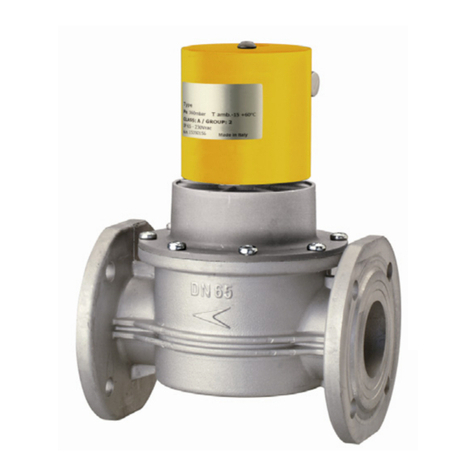
Geca AV015SO User manual

Italiano
ELETTROVALVOLE AUTOMATICHE
SLOW OPENING
AV015-SO
321
Valvole automatiche Dimensioni:
015 = 1/2”
020 = 3/4”
025 = 1”
032= 1” 1/4
040= 1”1/2
050= 2”
SO=Apertura lenta
Tutte le elettrovalvole sono a riarmo automatico e normalmente chiuse.
Esse infatti hanno bisogno di essere continuamente alimentate per restare
aperte.
Le elettrovalvole automatiche SLOW OPENING permettono la regolazione di:
- PORTATA.
-SCATTO di APERTURA.
-TEMPO di APERTURA.
Le elettrovalvole automatiche SLOW OPENING si chiudono automaticamente
se viene a mancare tensione alla bobina.
1 Tappo di protezione regolazioni.
2 Sistema ammortizzante.
3 Connettore per collegamento elettrico.
4 Bobina.
5 Tappo prese di pressione G 1/4”.
6 Corpo valvola.
7 Regolazione PORTATA.
8 Regolazione SCATTO di apertura.
9 Regolazione TEMPO di apertura.
3
1
4
5
6
2
INSTALLAZIONE
1 • Prima dell’installazione assicurarsi di chiudere il rubinetto del gas.
2 • L’elettrovalvola deve essere installata con la freccia stampata sul corpo
valvola rivolta verso l’utenza.
3 • Verificare che all’interno dell’ elettrovalvola non vi siano detriti o corpi estranei.
4 • Verificare che la pressione della linea non sia superiore alla pressione mas-
sima dichiarata dell’elettrovalvola.
5 • Verificare che la tensione di rete corrisponda alla tensione di alimentazione
della bobina dell’elettrovalvola.
6 • Verificare la tenuta dell’impianto.
N.B. L’installazione e manutenzione del prodotto deve essere eseguita
da personale qualificato.
230V
C1+
C 2-
Simboli che identicano i connet-
tori “raddrizzatori” (vedi tabella
Timbratura bobina).
8
7
DIMINUIZIONE PORTATA AUMENTO PORTATA
DIMINUIZIONE SCATTO APERTURA AUMENTO SCATTO APERTURA
DIMINUIZIONE TEMPO APERTURA AUMENTO TEMPO APERTURA
7
8
Senso antiorario
Senso antiorario
Senso orario
Senso orario
Senso orario
Senso antiorario
Con l’aiuto di un cacciavite piatto ruotare la vite nel senso desiderato:
Con l’aiuto di una chiave inglese o pinza ruotare il perno nel senso desiderato:
Con l’aiuto di un cacciavite piatto ruotare la vite nel senso desiderato:
REGOLAZIONE PORTATA
REGOLAZIONE SCATTO di APERTURA
REGOLAZIONE TEMPO di APERTURA
9
9
ATTENZIONE: NON ALLENTARE O TOGLIERE IL SISTEMA
AMMORTIZZANTE CON GAS IN PRESSIONE.
0497
DESCRIZIONE GENERALE
SLOW OPENING

La casa costruttrice riserva il diritto di apportare qualsiasi modifica, estetica o funzionale, senza preavviso alcuno
ed in qualsiasi momento.
CARATTERISTICHE TECNICHE
- Pressione max: 360mbar.
- Tempo di apertura (1/2” - 3/4” - 1”): da < 0,5 sec. a 25 secondi.
- Tempo di apertura (1”1/4 - 1”1/2 - 2” ): da < 0,5 sec. a 40 secondi.
- Tempo di chiusura: < 1 sec.
- Numero max operazioni: 20 al minuto.
- Alimentazione elettrica: 230Vac (-15%+10%) 50-60Hz.
- Regolazioni: Portata; Scatto di apertura, Tempo di apertura.
- Potenza elettrica: 15VA.
- Impiego: Gas non aggressivi (Metano, Propano, GPL....).
- Temperatura di lavoro: -20°C..... +60°C.
- Attacchi: da 1/2” a 2” lettati secondo ISO 228/1.
da DN65 a DN100 Flangiati secondo UNI 2223.
- Grado di protezione elettrica: IP65.
- Gruppo: 2.
- Conforme: Direttiva 97/23/CE (PED) (solo per modelli 6bar).
Direttiva 2009/142/CE (GAS) - EN161
GECA Srl
Via E. Fermi, n°98 25064 Gussago (BS)
Italy Tel. +39 030 3730218
www.gecasrl.it
Tecnocontrol Srl
Via Miglioli, n°47 20090 Segrate (MI)
Italy Tel. +39 02 26922890
www.tecnocontrol.it
A(mm)
196
196
196
320
320
320
B (mm)
68
68
68
154
154
154
C (mm)
72
72
72
164
164
164
φ
AV015SO
AV020SO
AV025SO
AV032SO
AV040SO
AV050SO
Misure d’ingombro in mm.
Attacchi lettati: da 1/2” a 2” secondo ISO 228/1. Corpo in alluminio.
Attacchi angiati: da DN65 a DN100 secondo UNI 2223. Corpo in alluminio.
TIMBRATURA BOBINA
:con queste bobine, utilizzare il connettore Cod. 2.180.1906 che
funge da “ritardatore” e “raddrizzatore”, presente nell’imballo.
230Vac
230VRAC 17W B
N.C.
B
Leggere attentamente il foglietto istruzioni prima dell’uso.
Questo dispositivo deve essere installato montando un ltro idoneo per gas (conforme alla norma EN161) a monte di esso, riferirsi
inoltre alle leggi in vigore per una corretta installazione.
L’elettrovalvola deve essere installata con la freccia stampata sul corpo rivolta verso l’utenza. Deve essere posizionata a monte
degli organi di regolazione e preferibilmente all’esterno dell’ambiente in cui è presente l’utenza.
N.B. Installare l’elettrovalvola al riparo dagli agenti atmosferici.
Si consiglia di vericare periodicamente l’intervento
dell’elettrovalvola. In caso di necessità, prima di effettuare qual-
siasi operazione sull’elettrovalvola, accertarsi che all’interno
della stessa non ci sia gas in pressione e che non sia alimen-
tata elettricamente. Qualsiasi operazione di manutenzione
dev’essere eseguita da personale qualicato.
NEUTRO
FASE TERRA
NO
Attacchi Posizione orizzontale Posizione verticale Posizione capovolta
da 1/2” a 2”
COLLEGAMENTO ELETTRICO
MANUTENZIONE
POSIZIONAMENTO
DIAGRAMMA PERDITE DI CARICO
DIMENSIONI (mm)
1”
1/4
1”
1/2
2”

English
AV015-SO
321
Automatic Valve Dimensions:
015 = 1/2”
020 = 3/4”
025 = 1”
032= 1” 1/4
040= 1”1/2
050= 2”
SO=Slow Opening
All solenoid valves are automatic reset and normally closed.
The automatic valves SLOW OPENING allow the regulation of:
- Flow rate.
- Rapid stroke.
- Opening time.
Gas automatic valve normally closed open when the coil is powered and close
when there is no tension.
1Protection cap for adjustments.
2Damping system.
3Electrical connector
4Coil.
5Test point G 1/4”.
6Valve body.
7Flow rate regulation.
8Rapid stroke regulation.
9Opening time regulation.
3
1
4
5
6
Made
in
Italy
2
1The gas supply must be shut off before installation.
2They must be installed with the arrow facing towards the user appliance.
3During installation take care not to allow debris or scraps of metal to enter
the device.
4Check the pressure in the line is not more then max pressure of the valve.
5 Check the voltage is the same as the coil voltage.
6Always check that the system is gas-tight after installation.
CAUTION: Installation and maintenence must be carried out only by
qualified technicians.
230V
C1+
C 2-
Identication symbol of the “rectier”
connectors. (see table coil marking)
8
7
FLOW DECREASING FLOW INCREASING
SLOW RAPID STROKE FAST RAPID STROKE
OPENING TIME DECREASING OPENING TIME INCREASING
7
8
Counter clockwise
Clockwise
With a at screwdriver rotate the screw in the desired direction:
With a wrench rotate the ferrule in the desired direction:
With a at screwdriver rotate the screw in the desired direction:
FLOW RATE
RAPID STROKE
OPENING TIME
Counter clockwise
Clockwise
0497
9
9
Counter clockwise Clockwise
WARNING: NOT SLACKEN OR REMOVE THE DAMPING SYSTEM
WITH GAS PRESSURIZED.
AUTOMATIC GAS VALVES
SLOW OPENING
SLOW OPENING
GENERAL DESCRIPTION
INSTALLATION VALVES

The manufacturer firm reserves the right to make any aesthetic or functional modification to the without prior notice
at any time.
TECHNICAL CHARACTERISTIC
- Max pressure: 360mbar
- Opening time (1/2” - 3/4” - 1”): from < 0,5 second to 25 seconds.
- Opening time (1”1/4 - 1”1/2 - 2” ): from < 0,5 second to 40 seconds.
- Closing time: < 1 sec.
- Max number of operations: 20 for minute.
- Supply voltage: 230Vac (-15%+10%) 50-60Hz
- Adjustments: Flow rate, Rapid stroke, Opening time.
- Power: 15VA
- Use: Non Aggressive gases (Family 1-2-3) and Air.
- Working temperature: -20°C..... +60°C.
- Connections: from 1/2” to 2” threaded as ISO 228/1
from DN65” to DN100 anging as UNI2223
- Degree of protection: IP65
- Group: 2
- Approval: Directive 97/23/CE (PED) (only for 6bar model)
Directive 2009/142/CE (GAS)-EN161
GECA Srl
Via E. Fermi, n°98 25064 Gussago (BS)
Italy Tel. +39 030 3730218
www.gecasrl.it
Tecnocontrol Srl
Via Miglioli, n°47 20090 Segrate (MI)
Italy Tel. +39 02 26922890
www.tecnocontrol.it
Overall measurements (mm)
Threaded connections: from 1/2” to 2” as ISO 228/1. Body in brass.
Flanging connections: from DN65 to DN100 as UNI 2229. Body in brass.
a particular (230Vca) connector must be associated to these coils
which acts as a “delayer” and “rectier” included in the packaging:
Cod.21801906.
230Vac
230VRAC 17W B
N.C.
B
Read instructions before use.
This devise must be installed by tting a suitable gas lter (according to UNI EN 161) upstream of it, also refers to the rules in force
for proper installation. The solenoid valve must be positioned with the arrow stamped on the body turned towards the user appli-
ance. The solenoid valve must be positioned with the arrow stamped on the body turner towards the user appliance upstream of
the regulation apparatus and preferably outside the measurement zone and repaired to the atmospheric agents.
The solenoid valve’s intervention should be checked periodi-
cally. Should disassembly be necessary, make sure there is no
gas under pressure inside the valve and that is not connected
to the power supply before starting. All maintenance operations
should be carried out by qualied personnel.
NO
Connection Horizontal position Vertical position Overtumed position
from 1/2” to 2”
NEUTRAL
PHASE GROUND
dis.8034092a Cod.2.710.2987 MADE IN ITALY
DIMENSIONS (mm) COIL MARKING
ELECTRICAL CONNECTION
MAINTENANCE
INSTALLATION AND POSITION
FLOW CHART
A(mm)
196
196
196
320
320
320
B (mm)
68
68
68
154
154
154
C (mm)
72
72
72
164
164
164
φ
AV015SO
AV020SO
AV025SO
AV032SO
AV040SO
AV050SO
1”
1/4
1”
1/2
2”
This manual suits for next models
5
Table of contents
Languages:
Other Geca Control Unit manuals
Popular Control Unit manuals by other brands

Phoenix Mecano
Phoenix Mecano Dewert Okin ACCUCONTROL 4.5 installation instructions

VitaLight
VitaLight 576841 user manual

Grundfos
Grundfos CIM 1 Series Installation and operating instructions

Kontron
Kontron ETX-LX2 manual

Vimar
Vimar by-me Eikon Evo 21509 quick start guide

Sanhua
Sanhua SBV Series instructions