Pololu 3pi Robot User manual

Pololu 3pi Robot User’s Guide
Pololu 3pi Robot User’s Guide © 2001–2019 Pololu Corporation
https://www.pololu.com/docs/0J21/all Page 1 of 85

1. Introduction . . . . . . . . . . . . . . . . . . . . . . . . . . . . . . . . . . . . . . . . . . . . . 3
2. Contacting Pololu . . . . . . . . . . . . . . . . . . . . . . . . . . . . . . . . . . . . . . . . . . 4
3. Important Safety Warning and Handling Precautions . . . . . . . . . . . . . . . . . . . . . . . 5
4. Getting Started with Your 3pi Robot . . . . . . . . . . . . . . . . . . . . . . . . . . . . . . . . 6
4.a. What You Will Need . . . . . . . . . . . . . . . . . . . . . . . . . . . . . . . . . . . . . 7
4.b. Powering Up Your 3pi . . . . . . . . . . . . . . . . . . . . . . . . . . . . . . . . . . . . 8
4.c. Using the Preloaded Demo Program . . . . . . . . . . . . . . . . . . . . . . . . . . . . 8
4.d. Included Accessories . . . . . . . . . . . . . . . . . . . . . . . . . . . . . . . . . . . 10
5. How Your 3pi Works . . . . . . . . . . . . . . . . . . . . . . . . . . . . . . . . . . . . . . . 11
5.a. Batteries . . . . . . . . . . . . . . . . . . . . . . . . . . . . . . . . . . . . . . . . . . 11
5.b. Power management . . . . . . . . . . . . . . . . . . . . . . . . . . . . . . . . . . . . 13
5.c. Motors and Gearboxes . . . . . . . . . . . . . . . . . . . . . . . . . . . . . . . . . . 15
5.d. Digital inputs and sensors . . . . . . . . . . . . . . . . . . . . . . . . . . . . . . . . . 20
5.e. 3pi Simplified Schematic Diagram . . . . . . . . . . . . . . . . . . . . . . . . . . . . . 23
6. Programming Your 3pi . . . . . . . . . . . . . . . . . . . . . . . . . . . . . . . . . . . . . . 26
7. xample Project #1: Line Following . . . . . . . . . . . . . . . . . . . . . . . . . . . . . . . 27
7.a. About Line Following . . . . . . . . . . . . . . . . . . . . . . . . . . . . . . . . . . . 27
7.b. A Simple Line-Following Algorithm for 3pi . . . . . . . . . . . . . . . . . . . . . . . . . 27
7.c. Advanced Line Following with 3pi: PID Control . . . . . . . . . . . . . . . . . . . . . . 35
8. xample Project #2: Maze Solving . . . . . . . . . . . . . . . . . . . . . . . . . . . . . . . . 37
8.a. Solving a Line Maze . . . . . . . . . . . . . . . . . . . . . . . . . . . . . . . . . . . . 37
8.b. Working with Multiple C Files in Atmel Studio . . . . . . . . . . . . . . . . . . . . . . . 37
8.c. Left Hand on the Wall . . . . . . . . . . . . . . . . . . . . . . . . . . . . . . . . . . . 41
8.d. The Main Loop(s) . . . . . . . . . . . . . . . . . . . . . . . . . . . . . . . . . . . . . 42
8.e. Simplifying the Solution . . . . . . . . . . . . . . . . . . . . . . . . . . . . . . . . . . 44
8.f. Improving the Maze-Solving Code . . . . . . . . . . . . . . . . . . . . . . . . . . . . . 51
9. Pin Assignment Tables . . . . . . . . . . . . . . . . . . . . . . . . . . . . . . . . . . . . . . 54
10. xpansion Information . . . . . . . . . . . . . . . . . . . . . . . . . . . . . . . . . . . . . 61
10.a. Serial slave program . . . . . . . . . . . . . . . . . . . . . . . . . . . . . . . . . . . 61
10.b. Serial master program . . . . . . . . . . . . . . . . . . . . . . . . . . . . . . . . . . 75
10.c. Available I/O on the 3pi's ATmegaxx8 . . . . . . . . . . . . . . . . . . . . . . . . . . 82
11. Related Resources . . . . . . . . . . . . . . . . . . . . . . . . . . . . . . . . . . . . . . . 84
12. Revision History and rrata . . . . . . . . . . . . . . . . . . . . . . . . . . . . . . . . . . . 85
Pololu 3pi Robot User’s Guide © 2001–2019 Pololu Corporation
Page 2 of 85

1. Introduction
Note: Starting with serial number 0J5840, 3pi robots are shipping with the newer
ATmega328P microcontroller instead of the ATmega168. The serial number is located
on a white bar code sticker on the bottom of the 3pi PCB. The ATmega328 is essentially
a drop-in replacement for the ATmega168 with twice the memory (32 KB flash, 2 KB
RAM, and 1 KB of PROM), so the 3pi code written for the ATmega168 should
work with minimal modification on the ATmega328 (the Pololu AVR Library
[https://www.pololu.com/docs/0J20] now supports the ATmega328P).
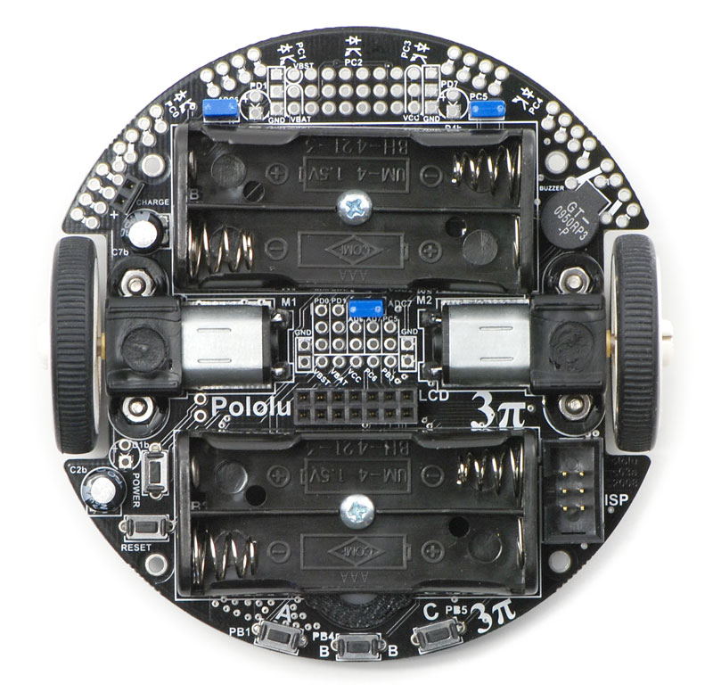
The Pololu 3pi robot is a small, high-performance, autonomous robot designed to excel in line-
following and line-maze-solving competitions. Powered by four AAA batteries (not included) and a
unique power system that runs the motors at a regulated 9.25 V, 3pi is capable of speeds up to 100
cm/second while making precise turns and spins that don’t vary with the battery voltage. This results
in highly consistent and repeatable performance of well-tuned code even as the batteries run low.
The robot comes fully assembled with two micro metal gearmotors, five reflectance sensors, an 8×2
character LCD, a buzzer, three user pushbuttons, and more, all connected to a user-programmable
AVR microcontroller. The 3pi measures approximately 3.7 inches (9.5 cm) in diameter and weighs 2.9
oz (83 g) without batteries.
The 3pi is based on an Atmel ATmega168 or ATmega328 microcontroller, henceforth referred to as
the “ATmegaxx8”, running at 20 MHz. ATmega168-based 3pi robots feature 16 KB of flash program
memory and 1 KB RAM, and 512 bytes of persistent PROM memory; ATmega328-based 3pi robots
feature 32 KB of flash program memory, 2 KB RAM, and 1 KB of persistent PROM memory.
The use of the ATmegaxx8 microcontroller makes the 3pi compatible with the popular Arduino
development platform. Free C and C++ development tools are also available, and an extensive set
of libraries make it a breeze to interface with all of the integrated hardware. Sample programs are
available to show how to use the various 3pi components, as well as how to perform more complex
behaviors such as line following and maze solving.
Please note that an external AVR ISP programmer, such as our USB AVR Programmer v2.1
[https://www.pololu.com/product/3172] is required to program the 3pi robot.
For a Spanish version of this document, please see Pololu 3pi Robot Guia Usuario
[https://www.pololu.com/file/0J137/Pololu3piRobotGuiaDeUsuario.pdf] (3MB pdf) (provided by
customer Jaume B.).
Pololu 3pi Robot User’s Guide © 2001–2019 Pololu Corporation
1. Introduction Page 3 of 85

2. Contacting Pololu
You can check the 3pi product page [https://www.pololu.com/product/975] for additional information,
including pictures, videos, example code, and other resources.
We would be delighted to hear from you about any of your projects and about your experience
with the 3pi robot. You can contact us [https://www.pololu.com/contact] directly or post on our forum
[http://forum.pololu.com/]. Tell us what we did well, what we could improve, what you would like to see in
the future, or share your code with other 3pi users.
Pololu 3pi Robot User’s Guide © 2001–2019 Pololu Corporation
2. Contacting Pololu Page 4 of 85

3. Important Safety Warning and Handling Precautions
The 3pi robot is not intended for young children! Younger users should use this product only under
adult supervision. By using this product, you agree not to hold Pololu liable for any injury or damage
related to the use or to the performance of this product. This product is not designed for, and should
not be used in, applications where the malfunction of the product could cause injury or damage. Please
take note of these additional precautions:
• Do not attempt to program your 3pi if its batteries are drained or uncharged. Losing power
during programming could permanently disable your 3pi. If you have purchased
rechargeable batteries for use with the 3pi, do not assume they come fully charged; charge
them before you first use them. The 3pi has the ability to monitor its battery voltage; the
example line-following and maze-solving programs we provide show how to use this feature,
and you should include it in your programs so you can know when its time to recharge or
replace your batteries.
• The 3pi robot is intended for use indoors on relatively flat, smooth surfaces. Avoid running
your 3pi on surfaces that might scrape or damage the underside of your robot’s PCB as it
drives around.
• Avoid placing the robot so that the underside of the PCB makes contact with conductive
materials (e.g. do not place the 3pi in a bin filled with metal parts). This could inadvertently
short out the batteries and damage your robot, even with the 3pi turned off. Shorting various
pads or components together could also damage your 3pi.
• Since the PCB and its components are exposed, take standard precautions to protect your
3pi robot from SD (electrostatic discharge), which could damage the on-board electronics.
When picking up the 3pi, you should first touch a safe part of the robot such as the wheels,
motors, batteries, or the edges of the PCB. If you first touch components on the PCB, you
risk discharging through them. When handing the 3pi to another person, first touch their hand
with your hand to equalize any charge imbalance between you so that you don’t discharge
through the 3pi as the exchange is made.
• If you remove the LCD, take care to replace it in the right orientation such that it is over the
rear battery back. It is possible to put the LCD in backwards or offset; doing so could damage
the LCD or the 3pi.
Pololu 3pi Robot User’s Guide © 2001–2019 Pololu Corporation
3. Important Safety Warning and Handling Precautions Page 5 of 85

4. Getting Started with Your 3pi Robot
Getting started with your 3pi can be as simple as taking it out of the box, adding batteries, and turning
it on. The 3pi ships with a demo program that will give you a brief tour of its features.
General features of the Pololu 3pi robot, top view.
Pololu 3pi Robot User’s Guide © 2001–2019 Pololu Corporation
4. Getting Started with Your 3pi Robot Page 6 of 85

Labeled bottom view of the Pololu 3pi robot.
The following subsections will give you all the information you need to get your 3pi up and running!
4.a. What You Will Need
The following materials are necessary for getting started with your 3pi:
•4 AAA batteries. Any AAA cells will work, but we recommend NiMH batteries, which are
rechargeable and can be purchased from Pololu [https://www.pololu.com/product/1002] or at a
local store. If you use rechargeable batteries, you will also need a battery charger. Battery
chargers designed to connect to external series battery packs, such as the iMAX-B6AC
[https://www.pololu.com/product/2588], may be used with the 3pi’s battery charger port.
•AVR ISP programmer with 6-pin connector. The 3pi features an ATmega328P
microcontroller, which requires an external programmer such as the Pololu USB AVR
Programmer v2.1 [https://www.pololu.com/product/3172] or Atmel’s AVRISP series. The 3pi has
Pololu 3pi Robot User’s Guide © 2001–2019 Pololu Corporation
4. Getting Started with Your 3pi Robot Page 7 of 85

a standard 6-pin programming connector, so your programmer will need to have a 6-pin ISP
cable [https://www.pololu.com/product/972] for connecting to the target device. (You will also need
whatever cable your programmer requires to connect to a computer.
•A desktop or laptop computer. You will need a personal computer for developing your
code and loading it onto the 3pi. The 3pi can be programmed on Windows, Mac, and Linux
operating systems, but Pololu support for Macs is limited.
You might find the following materials useful in creating an environment for your robot to explore:
• Several large sheets of white posterboard (available at crafts or office supply stores) or dry-
erase whiteboard stock (commonly available at home/construction supply stores).
• Light-colored masking tape for joining multiple sheets together.
• 3/4" black electrical tape to create lines for your robot to follow.
4.b. Powering Up Your 3pi
The first step in using your new 3pi robot is to insert four
AAA batteries into the battery holders. To do this you will
need to remove the LCD. Pay attention to the LCD’s
orientation as you will want to plug it back in this way
when you are done. With the LCD removed your 3pi
should look like the picture to the right.
Once the batteries are in place, you should return the
LCD to its position over the rear battery holder. Make
sure each male LCD header pin goes into a
corresponding female socket.
Next, push the power button (located on the left side of
the rear battery pack) to turn on your 3pi. You should see
the two blue power L Ds on the underside of the 3pi light, and the 3pi should begin running its
preloaded demo program. You can simply push the power button again to turn the 3pi off, and you can
push the reset button (located just below the power button) to reset the program the robot is running.
4.c. Using the Preloaded Demo Program
Your 3pi comes preloaded with a program that demonstrates most of its features and allows you to
test that it is working correctly. When you first turn on your 3pi, you will hear a beep and see the
words “Pololu 3pi Robot”, then “Demo Program” appear, indicating that you are running the demo
program. If you hear a beep but do not see any text on the LCD, you may need to adjust the contrast
Pololu 3pi Robot User’s Guide © 2001–2019 Pololu Corporation
4. Getting Started with Your 3pi Robot Page 8 of 85

potentiometer on the underside of the board. When the program has started successfully, press the
B button to proceed to the main menu. Press C or A to scroll forward or backward through the menu,
and press B to make a selection or to exit one of the demos. There are seven demos accessible from
the menu:
1. Battery: This demo displays the battery voltage in millivolts, which should be above 5000
(5.0 Volts) for a fully-charged set of batteries. Removing the jumper marked ADC6 will
separate the battery voltage measurement circuit from the analog input, causing the number
displayed to drop to some low value.
2. LEDs: Blinks the red and green user L Ds on the underside of the board. If you have
soldered in the optional user L Ds, they will also blink.
3. Trimpot: Displays the position of the user trimmer potentiometer, which is located on the
underside of the board, as a number between 0 and 1023. While displaying the value, this
demo also blinks the L Ds and plays a note whose frequency is a function of the current
reading. It is easiest to turn the trimpot using a 2mm flat-head screwdriver.
4. Sensors: Show the current readings of the IR sensors using a bar graph. Bigger bars mean
lower reflectance. Placing a reflective object such as your finger under one of the sensors will
cause the corresponding reading to drop visibly on the graph. This demo also displays “C” to
indicate that button C has an effect—press C and the IR emitters will be turned off. In indoor
lighting conditions away from bright incandescent or halogen lights, all of the sensors should
return entirely black readings with IR off. Removing the jumper marked PC5 disables control
of the emitters, causing them to always be on.
5. Motors: Hold down A or C to run the motor on the corresponding side, or hold down both
buttons to run both motors simultaneously. The motors will gradually ramp up to speed; in
your own programs, you can switch them on much more suddenly. Tap A or C to switch the
corresponding motor to reverse (the button letter becomes lowercase if pressing it will drive
the corresponding motor in reverse).
6. Music: Plays an adaptation of J. S. Bach’s Fugue in D Minor for microcontroller and piezo,
while scrolling a text display. This demonstrates the ability of the 3pi to play music in the
background.
7. Timer: A simple stopwatch. Press C to start or stop the stopwatch and A to reset. The
stopwatch continues to count while you are exploring the other demos.
Note: If the 3pi receives any serial data while the demo program is waiting for a button
press from the user, it will switch into serial slave mode. See Section 10.a for more
information.
Pololu 3pi Robot User’s Guide © 2001–2019 Pololu Corporation
4. Getting Started with Your 3pi Robot Page 9 of 85

The source code for the demo program is included with the Pololu AVR C/C++ Library described in
Section 6, in the folder examples\atmega328p\3pi-demo-program .
4.d. Included Accessories
The 3pi robot ships with two through-hole red L Ds and
two through-hole green L Ds. There are connection
points for three optional L Ds on your 3pi: one next to
the power button to indicate when the 3pi is on and two
user-controllable L D ports near the front edge of the
robot. Using these L Ds is completely optional as the 3pi
will function just fine without them. You can customize
your 3pi by choosing your desired combination of red and
green L Ds, or you can even use your own LEDs
[https://www.pololu.com/category/20/leds] if you want more
color/brightness options.
Note that you should only add L Ds if you are comfortable soldering, and you should take care to
avoid desoldering any of the components near the through-hole L D pads. L Ds are polarized, so be
sure to solder them such that the longer lead connects to the pad marked with the +. Before you solder
them in you can press-fit them in place and check to make sure they light as expected. Once soldered
in place, carefully trim off the excess portion of the L D leads.
Your 3pi also ships with three shorting blocks of each color: blue, red, yellow, black. This means you
can customize your 3pi by selecting the shorting block color you most prefer, or you can use a mixture
of colors!
Pololu 3pi Robot User’s Guide © 2001–2019 Pololu Corporation
4. Getting Started with Your 3pi Robot Page 10 of 85

Two rechargeable AAA Ni-MH
batteries.
5. How Your 3pi Works
5.a. Batteries
Introduction to Batteries
The power system on the 3pi begins with the batteries, so it is
important to understand how your batteries work. A battery
contains a carefully controlled chemical reaction that pulls
electrons in from the positive (+) terminal and pushes them out of
the negative (-) terminal. The most common type is the alkaline
battery, which is based on a reaction between zinc and
manganese through a potassium hydroxide solution. Once
alkaline batteries are completely discharged, they cannot be
reused. For the 3pi, we recommend rechargeable nickel-metal-
hydride (NiMH) batteries, which can be recharged over and over.
NiMH batteries are based on a different chemical reaction from
alkaline batteries, but you don’t need to know anything about the
chemical details to use a battery: everything you need to know about it is measured with a few simple
numbers. The first is the strength with which the electrons are pushed, which we measure in volts (V),
the units of electric potential. An NiMH battery has a voltage of about 1.2 V. To understand how much
power you can get out of a battery, you also need to know how many electrons the battery can push
per second – this is the electric current, measured in amps (A). A current of 1 A corresponds to about
6×10¹⁸ electrons flowing out one side and in to the other each second, which is such a huge number
that it’s easier to talk about it just in terms of amps. 1 A is also a typical current that a medium-sized
motor might use, and it’s a current that will put a significant strain on small (AAA) batteries.
For any battery, if you attempt to draw more and more current, the voltage produced by the battery will
drop, eventually dropping all the way to zero at the short circuit current: the current that flows if you
connect one side directly to the other with a thick wire. (Don’t try this! The wire might overheat and
melt, and the battery could explode.) The following graph shows a good model of how the voltage on
a typical battery drops as the current goes up:
Pololu 3pi Robot User’s Guide © 2001–2019 Pololu Corporation
5. How Your 3pi Works Page 11 of 85

Battery voltage vs. current.
The power put out by a battery is measured by multiplying the volts by the amps, giving a
measurement in watts (W). For example, at the point marked in the graph, we have a voltage of
0.9 V and a current of 0.6 A, this means that the power output is 0.54 W. If you want more power,
you need to add more batteries, and there are two ways to do it: parallel and series configurations.
When batteries are connected in parallel, with all of their positive terminals tied together and all of
their negative terminals tied together, the voltage stays the same, but the maximum current output is
multiplied by the number of batteries. When they are connected in series, with the positive terminal
of one connected to the negative terminal of the next, the maximum current stays the same while the
voltage multiplies. ither way, the maximum power output will be multiplied by the number of batteries.
Think about two people using two buckets to lift water from a lake to higher ground. If they stand next
to each other (working in parallel), they will be able to lift the water to the same height as before, while
delivering twice the amount of water. If one of them stands uphill from the other, they can work together
(in series) to lift the water twice as high, but at the same rate as a single person.
In practice, we only connect batteries in series. This is because different batteries will always have
slightly different voltages, and if they are connected in parallel, the stronger battery will deliver current
to the weaker battery, wasting power even when there is nothing else in the circuit. If we want more
current, we can use bigger batteries: AAA, AA, C, and D batteries of the same type all have the same
voltage, but they can put out very different amounts of current.
The total amount of energy in any battery is limited by the chemical reaction: once the chemicals are
exhausted, the battery will stop producing power. This happens gradually: the voltage and current
produced by a battery will steadily drop until the energy runs out, as shown in the graph below:
Pololu 3pi Robot User’s Guide © 2001–2019 Pololu Corporation
5. How Your 3pi Works Page 12 of 85

Battery voltage vs. time.
A rough measure of the amount of energy stored in a battery is given by its milliamp-hour (mAH)
rating, which specifies how long the battery will last at a given discharge rate. The mAH rating is the
discharge rate multiplied by how long the battery lasts: if you draw current at a rate of 200 mA (0.2 A),
and the battery lasts for 3 hours, you would call it a 600 mAH battery. If you discharge the same battery
at 600 mA, you would get about an hour of operation (however, battery capacity tends to decline with
faster discharge rates, so you might only get 50 minutes).
Note: If you have purchased rechargeable batteries for the 3pi, you should fully charge
them before you first use them. You should never attempt to program your 3pi if
its batteries are drained or uncharged. Losing power during programming could
permanently disable your 3pi.
5.b. Power management
Battery voltage drops as the batteries are used up, but many electrical components require a specific
voltage. A special kind of component called a voltage regulator helps out by converting the battery
voltage to a constant, specified voltage. For a long time, 5 V has been the most common regulated
voltage used in digital electronics; this is also called TTL level. The microcontroller and most of the
circuitry in the 3pi operate at 5 V, so voltage regulation is essential. There are two basic types of
voltage regulators:
•Linear regulators use a simple feedback circuit to vary how much energy is passed through
and how much is discarded. The regulator produces a lower output voltage by dumping
unneeded energy. This wasteful, inefficient approach makes linear regulators poor choices
for applications that have a large difference between the input and output voltages, or for
Pololu 3pi Robot User’s Guide © 2001–2019 Pololu Corporation
5. How Your 3pi Works Page 13 of 85

applications that require a lot of current. For example, 15 V batteries regulated down to 5 V
with a linear regulator will lose two-thirds of their energy in the linear regulator. This energy
becomes heat, so linear regulators often need large heat sinks, and they generally don’t work
well with high-power applications.
•Switching regulators turn power on and off at a high frequency, filtering the output to
produce a stable supply at the desired voltage. By carefully redirecting the flow of electricity,
switching regulators can be much more efficient than linear regulators, especially for high-
current applications and large changes in voltage. Also, switching regulators can convert low
voltages into higher voltages! A key component of a switching regulator is the inductor, which
stores energy and smooths out current; on the 3pi, the inductor is the gray block near the ball
caster labeled “100”. A desktop computer power supply also uses switching regulators: peek
through the vent in the back of your computer and look for a donut-shaped piece with a coil
of thick copper wire wrapped around it – that’s the inductor.
The power management subsystem built into the 3pi is shown in this block diagram:
The voltage of 4 x AAA cells can vary between 3.5 – 5.5 V (and even to 6 V if alkalines are used).
This means it’s not possible simply to regulate the voltage up or down to get 5 V. Instead, in the
3pi, a switching regulator first boosts the battery voltage up to 9.25 V (Vboost), and a linear regulator
regulates Vboost back down to 5 V (VCC). Vboost powers the motors and the IR L Ds in the line
sensors, while VCC is used for the microcontroller and all digital signals.
Using Vboost for the motors and sensors gives the 3pi three unique performance advantages over
typical robots, which use battery power directly:
• First, a higher voltage means more power for the motors, without requiring more current and
Pololu 3pi Robot User’s Guide © 2001–2019 Pololu Corporation
5. How Your 3pi Works Page 14 of 85

a larger motor driver.
• Second, since the voltage is regulated, the motors will run the same speed as the batteries
drop from 5.5 down to 3.5 V. You can take advantage of this when programming your 3pi, for
example by calibrating a 90° turn based on the amount of time that it takes.
• Third, at 9.25 V, all five of the IR L Ds can be powered in series so that they consume the
lowest possible amount of power. (Note that you can switch the L Ds on and off to save even
more power.)
One other interesting thing about this power system is that instead of gradually running out of power
like most robots, the 3pi will operate at maximum performance until it suddenly shuts off. This can take
you by surprise, so you might want your 3pi to monitor its battery voltage.
A simple circuit for monitoring battery voltage is built in to the 3pi.
Three resistors, shown in the circuit at right, comprise a voltage
divider that outputs a voltage equal to two-thirds of the battery
voltage, which will always be safely below the main microcontroller’s
maximum analog input voltage of 5 V. For example, at a battery
voltage of 4.8 V, the battery voltage monitor port ADC6 will be at a
level of 3.2 V. Using 10-bit analog-to-digital conversion, where 5 V is
read as a value of 1023, 3.2 V is read as a value of 655. To convert
it back to the actual battery voltage, multiply this number by
5000 mV×3/2 and divide by 1023. This is handled conveniently by
the read_battery_millivolts_3pi() function (provided in the Pololu
AVR Library; see Section 6 for more information), which averages ten samples and returns the battery
voltage in mV:
5.c. Motors and Gearboxes
1
2
3
4
unsigned int read_battery_millivolts_3pi()
{
return readAverage(6,10)*5000L*3/2/1023;
}
?
Pololu 3pi Robot User’s Guide © 2001–2019 Pololu Corporation
5. How Your 3pi Works Page 15 of 85

A typical small brushed DC
motor, with no gearbox.
A motor is a machine that converts electrical energy to motion.
There are many different kinds of motors, but the most important
for low-cost robotics is the brushed DC motor, which is the type
used on the 3pi. A brushed DC motor typically has permanent
magnets on the outside and several electromagnetic coils
mounted on the motor shaft (armature). The “brushes” are sliding
pieces of metal that switch the power from one coil to the next as
the shaft turns so that magnetic attraction between the coil and
the magnets continuously pulls the motor in the same direction.
The primary values that describe a running motor are its speed,
measured in rpm, and its torque, measured in kg·cm or oz·in
(pronounced “ounce-inches”). The units for torque show the dependence on both force and distance;
for example, a motor that produces 6 oz·in of torque can product a force of 6 oz. with a 1-inch lever
arm, 3 oz. with a 2-inch lever, and so on. Multiplying the torque and speed (measured at the same
time) give us the power delivered by a motor. We see, therefore, that a motor with twice the speed and
half the torque as another has the same power output.
very motor has a maximum speed (when no force is applied) and a maximum torque (when the motor
is completely stopped). We call these the free-running speed and the stall torque. Naturally, a motor
uses the least current when no force is applied to it, and the current drawn from the batteries goes up
until it stalls, so the free-running current and stall current are also important parameters characterizing
the motor. The stall current is usually much higher than the free-running current, as shown in the graph
below:
Motor operation: current and speed vs. torque.
Pololu 3pi Robot User’s Guide © 2001–2019 Pololu Corporation
5. How Your 3pi Works Page 16 of 85

The 30:1 gearmotor used on the
3pi.
The free-running speed of a small DC motor is usually many
thousands of rotations per minute (rpm), much higher than the
speed we want the wheels of a robot to turn. A gearbox is a
system of gears that converts the high-speed, low-torque output
of the motor into a lower-speed, higher-torque output that is a
much better suited for driving a robot. The gear ratio used on the
3pi is 30:1, which means that for every 30 turns of the motor shaft,
the output shaft turns once. This reduces the speed by a factor of
30, and (ideally) increases the torque by a factor of 30. The
resulting parameters of the 3pi motors are summarized in this
table:
Gear ratio: 30:1
Free-running speed: 700 rpm
Free-running current: 60 mA
Stall torque: 6 oz·in
Stall current: 540 mA
The two wheels of the 3pi each have a radius of 0.67 in, which means that the maximum force it can
produce with two motors when driving forward is 2×6/0.67 = 18 oz. The 3pi weighs about 7 oz with
batteries, so the motors are strong enough to lift the 3pi up a vertical slope or accelerate it at 2 g (twice
the acceleration of gravity). The actual performance is limited by the friction of the tires: on a steep
enough slope, the wheels will slip before they stall – in practice, this happens when the slope is around
30-40°.
Driving a motor with speed and direction control
One nice thing about a DC motor is that you can change the direction of rotation by switching the
polarity of the applied voltage. If you have a loose battery and motor, you can see this for yourself by
making connections one way and then turning the battery around to make the motor spin in reverse.
Of course, you don’t want to take the batteries out of your 3pi and reverse them every time it needs
to back up – instead, a special arrangement of four switches, called an H-bridge, allows the motor to
spin either backwards or forwards. Here is a diagram that shows how the H-bridge works:
Pololu 3pi Robot User’s Guide © 2001–2019 Pololu Corporation
5. How Your 3pi Works Page 17 of 85

If switches 1 and 4 are closed (the center picture), current flows through the motor from left to right,
and the motor spins forward. Closing switches 2 and 3 causes the current to reverse direction and the
motor to spin backward. An H-bridge can be constructed with mechanical switches, but most robots,
including the 3pi, use transistors to switch the current electronically. The H-bridges for both motors
on the 3pi are all built into a single motor driver chip, the TB6612FNG, and output ports of the main
microcontroller operate the switches through this chip. Here is a table showing how output ports PD5
and PD6 on the microcontroller control the transistors of motor M1:
PD5 PD6 1 2 3 4 M1
0 0 off off off off off (coast)
0 1 off on on off forward
1 0 on off off on reverse
1 1 off off on on off (brake)
Motor M2 is controlled through the same logic by ports PD3 and PB3:
PD3 PB3 1 2 3 4 M2
0 0 off off off off off (coast)
0 1 off on on off forward
1 0 on off off on reverse
1 1 off off on on off (brake)
Pololu 3pi Robot User’s Guide © 2001–2019 Pololu Corporation
5. How Your 3pi Works Page 18 of 85

PWM speed control, showing gradual deceleration.
Speed control is achieved by rapidly
switching the motor between two states in
the table. Suppose we keep PD6 high (at 5 V,
also called a logical “1”) and have PD5
alternate quickly between low (0 V or “0”) and
high. The motor driver will switch between
the “forward” and “brake” states, causing M1
to turn forward at a reduced speed. For
example, if PD6 is high two thirds of the time
(a 67% duty cycle), then M1 will turn at
approximately 67% of its full speed. Since
the motor voltage is a series of pulses of
varying width, this method of speed control is
called pulse-width modulation (PWM). An
example series of PWM pulses is shown in the graph at right: as the size of the pulses decreases from
100% duty cycle down to 0%, the motor speed decreases from full speed down to a stop.
In the 3pi, speed control is accomplished using special PWM outputs of the main microcontroller that
are linked to the internal timers Timer0 and Timer2. This means that you can set the PWM duty cycle
of the two motors once, and the hardware will continue to produce the PWM signal, in the background,
without any further attention.
The set_motors() function in the Pololu AVR Library (see Section 6 for more information) lets you
set the duty cycle, and it uses 8-bit precision: a value of 255 corresponds to 100% duty cycle. For
example, to get 67% on M1 and 33% on M2, you would call
To get a slowly decreasing PWM sequence like the one shown in the graph, you would need to write
a loop that gradually decreases the motor speed over time.
Turning with a differential drive
The 3pi has an independent motor and wheel on each side, which enables a method of locomotion
called differential drive. It is also known as a “tank drive” since this is how a tank drives. It is completely
unlike the steering system of automobile, which uses a single drive motor and steerable front wheels.
Turning with a differential drive is accomplished by running the two motors at different speeds. In the
previous set_motors() example, the left wheel will spin faster than the right, driving the robot forward
and to the right. The difference in speeds determines how sharp the turn will be, and spinning in place
can be accomplished by running one motor forward and one backward. Spinning is an especially
effective maneuver for a round robot, and you won’t have to worry about parallel parking!
1set_motors(171,84); ?
Pololu 3pi Robot User’s Guide © 2001–2019 Pololu Corporation
5. How Your 3pi Works Page 19 of 85

The 3pi demonstrating the effects of various motor
settings.
5.d. Digital inputs and sensors
The microcontroller at the heart of the 3pi, an Atmel AVR mega168 or mega328, has a number of pins
which can be configured as digital inputs: they are read by your program as a 1 or a 0 depending on
whether the voltage is high (above about 3 V) or low (below about 1.5 V). Here is the circuit for one of
the pushbutton inputs:
Normally, the pull-up resistor R (20-50 k) brings the voltage on the input pin to 5 V, so it reads as a 1,
but pressing the button connects the input to ground (0 V) through a 1 k resistor, which is much lower
than the value of R. This brings the input voltage very close to 0 V, so the pin reads as a 0. Without the
pull-up resistor, the input would be “floating” when the button is not pressed, and the value read could
be affected by residual voltage on the line, interference from nearby electrical signals, or even distant
lightning. Don’t leave an input floating unless you have a good reason. Since the pull-up resistors are
important, they are included within the AVR – the resistor R in the picture represents this internal pull-
Pololu 3pi Robot User’s Guide © 2001–2019 Pololu Corporation
5. How Your 3pi Works Page 20 of 85
This manual suits for next models
1
Table of contents
Other Pololu Robotics manuals