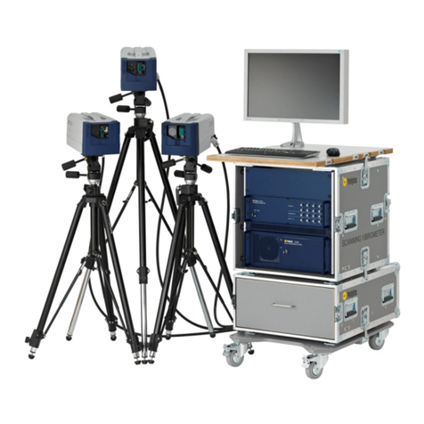
Polytec PSV-500 User manual

Title
Hardware Manual
Polytec Scanning Vibrometer
PSV-500
Scanning Head PSV-I-500
Front-End PSV-F-500-HM
Junction Box PSV-E-530
PC PSV-W-500-M
For the PSV-500-HM System

41529-Man-Vib-PSV500-HM-0214-04en *41529*
Warranty and Service
The warranty for this equipment complies with the regulations in our general terms and
conditions in their respective valid version.
This is conditional on the equipment being used as intended and as described in this manual.
The warranty does not apply to damage caused by incorrect usage, external mechanical
influences or by not keeping to the operating conditions. The warranty also is invalidated in the
case of the equipment being tampered with or modified without authorization.
To return the equipment always use the original packaging. Otherwise we reserve the right to
check the equipment for transport damage. Please mark the package as fragile and sensitive to
frost. Include an explanation of the reason for returning it as well as an exact description of the
fault. You will find information on fault diagnosis in
CHAPTER
6.
Trademarks
Brand or product names mentioned in this manual could be trademarks or registered
trademarks of their respective companies or organizations.
Identification Labels
PSV-F-500-HM Front-End PSV-E-530 Junction Box PSV-I-500 Scanning Head
PSV-W-500-M Data
Management System
PSV-A-T11 Pan-Tilt Head
(Optional)
PSV-A-T18 Test Stand
(Optional)

i
Contents
Contents
1 Safety Information 1-1
1.1 General Safety Information ................................................................................................. 1-1
1.2 Information on Laser Safety ............................................................................................... 1-2
1.2.1 Safety Information .................................................................................................... 1-2
1.2.2 Safety Precautions ................................................................................................... 1-3
1.2.3 Laser Warning Labels .............................................................................................. 1-4
1.3 Information on Electrical Safety ......................................................................................... 1-5
1.3.1 Safety Information .................................................................................................... 1-5
1.3.2 Safety Precautions ................................................................................................... 1-5
2 Introduction 2-1
2.1 Area of Application and System Summary ......................................................................... 2-1
2.2 Signal Flow between the System Components ................................................................... 2-2
2.2.1 Principle ................................................................................................................... 2-2
2.2.2 Decoder ...................................................................................................................2-3
2.3 Different Operating Modes ................................................................................................. 2-3
3 First Steps 3-1
3.1 Unpacking and Inspection .................................................................................................. 3-1
3.2 Operating and Maintenance Requirements ........................................................................ 3-2
3.3 Control Elements, Indicators and Connections ................................................................... 3-4
3.3.1 PSV-F-500-HM Front-End ......................................................................................... 3-4
3.3.2 PSV-E-530 Junction Box ........................................................................................... 3-6
3.3.3 PSV-W-500-M PC .................................................................................................... 3-7
3.3.4 PSV-I-500 Scanning Head .......................................................................................3-11
3.4 Assembly ......................................................................................................................... 3-14
3.4.1 Scanning Head ...................................................................................................... 3-15
3.4.2 VIB-A-T02 Light Duty Tripod with Fluid Head ......................................................... 3-16
3.4.3 PSV-A-013 System Cabinet ................................................................................... 3-17
3.5 Cabling ............................................................................................................................ 3-20
3.5.1 Connecting the Hardware........................................................................................ 3-20
3.5.2 Connecting the Signals (M System) ........................................................................ 3-24
3.5.3 Connecting the Signals (H System) ......................................................................... 3-25
3.5.4 Connecting the Mains Cables ................................................................................. 3-26
3.6 Functional Test ................................................................................................................ 3-26
4 Making Measurements 4-1
4.1 Starting the System ............................................................................................................ 4-1
4.2 Selecting Suitable Settings ................................................................................................ 4-2
4.2.1 Measurement Range ................................................................................................ 4-2
4.2.2 Tracking Filter .......................................................................................................... 4-3
ii
Contents
4.3 Setting up Optimal Stand-off Distances ...............................................................................4-5
4.3.1 Relation between Stand-Off Distance and Visibility Maximum ...................................4-5
4.3.2 Optimal Stand-Off Distances .....................................................................................4-6
4.3.3 Optimal Stand-off Distances with PSV-A-560 CoherenceOptimizer (optional) ............4-7
5 Operating the PSV 5-1
5.1 Switching On and Off ..........................................................................................................5-1
5.2 Blocking the Laser Beam ....................................................................................................5-1
5.3 Indicating Laser Activity ......................................................................................................5-2
5.4 Setting up the Scanning Head .............................................................................................5-2
6 Fault Diagnosis 6-1
6.1 General Tests .....................................................................................................................6-1
6.2 Problems with the Laser .....................................................................................................6-2
6.2.1 No Laser Beam .........................................................................................................6-2
6.2.2 Highly Fluctuating Signal Level Display .....................................................................6-3
6.3 No Measurement Signal or Implausible Measurement Signals ............................................6-3
7 Technical Specifications 7-1
7.1 Harmonized Standards Applied ...........................................................................................7-1
7.2 PSV-F-500-HM Front-End ...................................................................................................7-1
7.2.1 General Data ............................................................................................................7-1
7.2.2 Signal Inputs and Outputs .........................................................................................7-2
7.2.3 Metrological Properties .............................................................................................7-3
7.2.4 Data Acquisition (H System) .....................................................................................7-7
7.3 PSV-W-500-M PC ...............................................................................................................7-7
7.3.1 General Data ............................................................................................................7-7
7.3.2 PC Configuration .......................................................................................................7-7
7.3.3 Data Acquisition (M System) .....................................................................................7-8
7.4 PSV-E-530 Junction Box .....................................................................................................7-8
7.4.1 General Data ............................................................................................................7-8
7.4.2 Signal Inputs and Outputs .........................................................................................7-8
7.5 PSV-I-500 Scanning Head ..................................................................................................7-9
7.5.1 General Data ............................................................................................................7-9
7.5.2 Optics .....................................................................................................................7-12
7.5.3 Scanner ..................................................................................................................7-13
7.5.4 Video Camera (Only PSV-I-500) .............................................................................7-14
7.6 PSV-A-013 System Cabinet ..............................................................................................7-14
Appendix A: Optional Accessories
Appendix B: Basics of the Measurement Procedure
Appendix C: Declaration of Conformity
Index

1-1
1 Safety Information
1.1 General Safety Information
Notes
Please read this manual before using the instrument. It will provide you with
important information on using the instrument and on safety. This allows you
to protect yourself and prevents any damage being done to the instrument.
Pay particular attention to the basic safety information in
CHAPTER
1 and the
information on installation, operation and maintenance in
CHAPTER
3.
Keep this manual in a safe place and make it available to people using the
instrument. Never pass the instrument on without the manual.
In this manual, the following graded safety and warning labels are used:
NOTE!
Identifies an action that simplifies the usage of the instrument as well as requirements for a
safe usage!
CAUTION!
"Type and source of danger"! Identifies the danger caused by an action which could
result in damage to the instrument and how you can avoid it!
WARNING!
"Type and source of danger"! Identifies a possible danger resulting from an action which
could lead to death or (serious) injury and how you can avoid it !
Intended use
The instrument is intended for use in a laboratory and for operation in an
industrial environment. It may only be operated within the limits specified in
the technical specifications (refer to
CHAPTER
7).
Faultless and safe operation of the instrument presume proper transport and
proper storage, installation and assembly as well as careful operation of the
instrument.
When assembling, installing and operating the instrument, the safety and
accident-prevention regulations for the respective use must be adhered to.
Qualification
This instrument may only be operated by persons who are familiar with
electrical measurement equipment and have been instructed in the use of
lasers. Please pay attention to the information on laser safety in
SECTION
1.2.
Intervention for maintenance and repair work may only be carried out by the
manufacturer himself or by qualified personnel authorized by the
manufacturer.
Disposal
An instrument which is no longer required must be disposed of according to
the local regulations unless otherwise provided by the manufacturer.

1-2
1 Safety Information
1.2 Information on Laser Safety
1.2.1 Safety Information
The light source of the instrument is a laser. It is important to understand that
laser light has different properties from ordinary light sources. Laser light is
generally extremely intense due to the beam's low divergence. When
handling lasers, great care should be taken in any case to make sure that the
direct or reflected beam does not enter the eye.
NOTE!
For the detailed technical specifications, see
CHAPTER
7!
General
The protective measures described in the following support compliance with
the safety standards for
Laser Class 2
:
•
Polytec instruments generally comply with the standards
IEC
and
EN 60825-1
respectively
US 21 CFR 1040.10
and
1040.11
except for
deviations pursuant to Laser Notice no. 50, dated 24 June 2007.
•
The optical output power of the laser beam emitted from the instrument is
less than 1mW provided the equipment is used in the manner for which it
was intended. This means that the instrument conforms with
laser class 2
and is generally very safe. It is thereby usually assumed that eyes are
protected by prevention mechanisms including the blink reflex. This
reaction offers appropriate protection under reasonably foreseeable
operating conditions. This includes the use of optical instruments for
observing the laser beam. Even when optimally focused, the laser beam
is not intense enough to harm the skin.
•
The user should not attempt to open the housing of the instrument which
contains the laser unit as he could be exposed to a higher level of laser
radiation that is potentially hazardous.
•
Use of controls or adjustments or performance of procedures other than
those specified here may result in hazardous radiation exposure.
Specific
•
An
emission indicator
on the scanning head indicates the activity of the
installed laser and thus the potential hazard of laser beams emitted.
•
The laser is switched on using the
key switch
on the front-end. The key
can only be removed if the front-end and therefore also the laser is
switched off.

1-3
1 Safety Information
1.2.2 Safety Precautions
Pay attention to the following safety precautions when using the instrument:
•
Only qualified and fully trained persons should be entrusted with setting
up the instrument, adjusting and operating it!
•
Avoid looking directly into the laser beam with the naked eye or with the
aid of mirrors or optical instruments!
•
Wear suitable laser adjustment eyewear when you have to look at the
target area of the laser beam long and hard to set it up!
•
Never intentionally direct the laser beam at anyone!
•
Do not use any reflective tools, watches etc. when you are working in the
beam path of the laser!
•
Avoid staying in the scanning area! The laser beam can exit the scanning
head in an angle of ± 25°!
•
Always close the beam shutter, before positioning the scanning head. The
beam shutter should not be opened until the scanning head has been
roughly aligned and mounted securely!
•
The laser beam should be terminated at the end of its intended path
where this is practically possible.
•
Instruments which are not in use should be stored in places which
unauthorized persons do not have access to.

1-4
1 Safety Information
1.2.3 Laser Warning Labels
Warning labels
The laser warning labels are shown in the following figure. For countries in the
European Union (EU), labels 2 and 3 are affixed in the language spoken in
the customer's country (see right-hand-side).
Figure 1.1: Laser warning labels
Position
The position of the laser warning labels on the scanning head and of the
beam exit aperture is shown in the following figure.
Figure 1.2: Position of the laser warning labels on the scanning head
Beam
1
3
2

1-5
1 Safety Information
1.3 Information on Electrical Safety
1.3.1 Safety Information
The instrument complies with the electrical protection class 1 in accordance
with the EU Directive 2006/95/ EC (Low Voltage Directive). With correct
mains connection and intended use, exposure to electric current is prevented
by the closed, grounded metal housing.
The instrument is subjected to the EU Directive 2004/108/ EC (EMC
Directive) and therefore complies with the limit values for emission and
immunity of the standards they are based on (refer also to
SECTION
7.1 and
APPENDIX
C).
CAUTION!
Impairment caused by radio interference! This device is subjected to Limit Class A and
can cause radio interferences in residential areas. In this case, the user has to carry out
appropriate measures.
1.3.2 Safety Precautions
Pay attention to the following safety precautions when using the instrument:
•
The instruments may only be connected up using a three-pin mains cable
to AC systems 50/60Hz with a grounded protective conductor, and a
nominal voltage of between 100V and 240V.
•
Defective mains fuses may only be replaced by fuses of the same kind
with the rating given on the instrument.
•
If the mains switch is not freely accessible the mains plug is used as a
separator in case of danger. This means that the mains plug needs to be
freely accessible. Otherwise an additional disconnection device must be
installed.
•
The housing may not be opened when using the instrument as intended.
Opening the housing will invalidate the warranty. None of the instruments
may be operated with opened housing.
•
Maintenance and repair work may only be carried out by the manufacturer
or by qualified persons authorized by the manufacturer.
•
Disconnect the mains plug before you remove parts of the housing for
installation and servicing purposes.
•
Existing air inlets and outlets must always be kept free to allow sufficient
cooling. If you notice that a cooling fan is not working, immediately switch
off the affected instrument.

1-6
1 Safety Information

2-1
2 Introduction
2 Introduction
2.1 Area of Application and System Summary
The Polytec Scanning Vibrometer PSV measures the two-dimensional
distribution of vibrational velocity on the basis of laser interferometry. The
system components are shown in the following figure.
Figure 2.1: System components of the PSV-500-HM
Polytec Scanning Vibrometers consist of the basic components optics
(scanning head), electronics (front-end), junction box and control (data
management system). The components are adapted to suit the intended area
of application and can be customized by adding accessories and upgrading
the hardware. The decoders to analyze the vibrometer signal are designed as
digital wide range decoders and thus fit into the digital signal concept.
The scanning head consists of the interferometer, the scanner mirrors to
deflect the laser beam, and a video camera to visualize the measurement
object. As an option, the scanning head contains the geometry scan unit and
the CoherenceOptimizer (for the stabilization of laser modes). The PSV-A-515
digital video camera is available as an accessory. Then you can set which
video camera is being used in the software.
In the front-end the interferometer signal of the vibrometer is demodulated
using a velocity decoder and is transmitted to the PC. Synchronously to the
vibrometer data, reference channels are acquired and generator signals are
emitted. The front-end is applied for the operation as an H system and covers
bandwidths up to 100kHz.
The PSV-E-530 junction box provides the connections for the reference
channels and generator signals for the operation as an M system with
bandwidths of more than 100kHz.
The measurement data is acquired and saved in the PC. The PSV software
controls the entire measurement system and offers user-friendly functions to
evaluate the measurement data.
ICP1
SIGNAL3SIGNAL4
SIGNAL2
SIGNAL1
TRIGIN
AUXOUT
AUXIN SYNC
REF1REF2REF3REF4
REF5REF6REF7 REF8
ANALOG IN
GENERATOR OUT
DIGITALI/O
POWER
O
I
ICP4
PSV-500
VIBROMETER FRONT-END
ICP2ICP3
ICP5ICP6ICP7ICP8
DMS
DATA MANAGEMENT SYSTEM
Scanning head
Front-end
Junction box
PC

2-2
2 Introduction
2.2 Signal Flow between the System Components
2.2.1 Principle
In the front-end, the high-frequency Doppler signal coming from the scanning
head is fed in the decoder. Here, the velocity information is extracted from the
signal. You can run the system either as a PSV-500-H or as a PSV-500-M. To
do so, when starting the software select the corresponding data acquisition
board: Ethernet for the operation as an H system or PCI-6110 for the
operation as an M system.
Operation as an
H system
Synchronously to the decoder, analog reference signals are acquired and
generator signals are emitted in the front-end. The digital measurement data
is exchanged with the PC via an Ethernet interface. The signal flow in the
system is shown in the following figure.
Figure 2.2: Schematic diagram of the signal flow in the PSV-500-HM (H system)
Operation as an
M system
On the junction box, analog reference signals are connected and generator
signals are emitted. The measurement data is transmitted as analog signals
to the PC. The signal flow is shown in the following figure.
Figure 2.3: Schematic diagram of the signal flow in the PSV-500-HM (M system)
PC
Generator signals
Referencesignals
Camerasignal
Control signal
Vibrometer signals
Generator channels D/A
Referencechannels A/D
Decoder
Front-end
Camerasignal
Control signal
Doppler signal
Scanning head
Generator
D/A
Vibrometer,
Reference
A/D
PC
Generator signals
Referencesignals
Camerasignal
Control signal
Vibrometer signals
Generator connections
Referenceconnections
Junction box
Decoder
Front-end
Camerasignal
Control signal
Doppler signal
Scanning head

2-3
2 Introduction
2.2.2 Decoder
In the PSV-500-HM the digital velocity decoder DV-04 is used. It enables very
precise and high-resolution acquisition of vibrations. With the PSV-500-H, the
decoder signals are directly transmitted digitally to the PC. With the
PSV-500-M the signals are converted into analog signals and transmitted to
the data acquisition board of the PC.
The decoder is equipped with digital tracking filters which allow undisturbed
measurements, even if the optical signals are weak.
DV-04
With 13 measurement ranges, the DV-04 velocity decoder covers the
frequency range from 0Hz to 2 MHz.
2.3 Different Operating Modes
The decoder and the filter in the front-end as well as the data acquisition
board determine the metrological properties of the PSV. Depending on the
application, there are different operating modes available. Their properties
are summarized in the following table.
Table 2.1: Overview of the operating modes
PSV-500-HM
(H system)
PSV-500-HM
(M system)
Junction box – PSV-E-530
Front-end PSV-F-500-HM PSV-F-500-HM
Velocity decoder DV-04 DV-04
Measurement ranges
[mm/s] 13 ranges, 1 to 10000 13 ranges, 1 to 10000
Maximum frequency 100kHz 1MHz (2MHz)
1
1
The specifications in brackets are available as an option.
PC PSV-W-500-M PSV-W-500-M
Data acquisition PSV-F-500-HM PCI-6110
Reference channels 4 (8)
1
3
Maximum bandwidth 100kHz 1MHz (2MHz)
1
Function generator PSV-F-500-HM M2i.6030
Output channels 4 1
Maximum bandwidth 100kHz 1MHz (2MHz)
1

2-4
2 Introduction

3-1
3 First Steps
3 First Steps
NOTE!
The components marked with an (*) are described in detail in separate manuals!
3.1 Unpacking and Inspection
CAUTION!
Misalignment caused by shock! Protect the unpacked scanning heads from hard
shocks !
Unpacking
The scope of supply includes the following components:
•
PSV-F-500-HM front-end
•
PSV-E-530 junction box
•
PSV-I-500 scanning head
•
PSV-W-500-M data management system consisting of industrial PC with
mouse and keyboard
•
TFT monitor with monitor cable and mains cable
•
VIB-A-T02 light duty tripod with fluid head
•
Acquisition cable (ACQ HM)
•
SMB-SMB connecting cable
•
2 BNC-SMB connecting cables
•
Main cable (Umbilical)
•
Mains cable for the multiple mains socket
•
3 mains cables for the system components
•
3 BNC cables
•
3 network cables
Available as an option:
•
PSV-A-013 system cabinet
•
PSV-A-410 close-up unit
•
PSV-A-430 acoustic gate unit with BNC cable*
•
PSV-A-T11 heavy duty tripod with motorized pan-tilt head, connector box
and mains cable (instead of the VIB-A-T02)
•
PSV-A-T18 test stand
•
PSV-A-515 digital video camera with standard lens (optionally with zoom
lens), IEEE-1394 cable (FireWire®) and tripod adapter angle
•
Optical PSV-A-HNeBF block filter for the video camera of the scanning
head
•
VIB-A-T05 tripod with geared head
•
PSV-A-525 protective window
•
Laser adjustment eyewear

3-2
3 First Steps
Inspection
Please pay attention to the following steps when unpacking:
1. Check the packaging for signs of unsuitable handling during transport.
2. After unpacking, check all components for external damage (scratches,
loose screws, damaged components etc.).
3. In the case of a wrong delivery, damage or missing parts, immediately
inform your local Polytec representative, stating the serial number of the
instrument. The serial number can be found on the identification label.
You will find the identification label on the instruments (refer to
SECTION
3.3) as well as on the inside cover of this manual.
4. Carefully retain the original packaging in case you have to return the
instruments.
Install the instrument and carry out a first functional test as described in
SECTION
3.6.
3.2 Operating and Maintenance Requirements
Ambient
conditions
The instrument can be operated in dry rooms under normal climatic conditions
(refer to specifications in
CHAPTER
7). In particular the optical components are
sensitive to moisture, high temperatures, vibrations and dirt.
If you start operating the instrument after storing it in a cold environment,
allow a sufficient acclimatization period before switching it on. Avoid
condensing moisture on the optical components as a result of a rapid
temperature change.
Assembly
A scanning head must not be set up provisionally but must be securely
mounted as free of vibration as possible on a stable tripod or an alternative
stable base using the mounting threads.
Cooling
Remove the covers of the system cabinet, before you are operating the
instrument in the system cabinet.
Always keep the air inlets free. The distance to the wall must be at least
50mm! Provide sufficient free space under the instrument as air vents are
located there!
Cooling of the
scanning head
At ambient temperatures above 35°C (95°F) you may only operate the
scanning head if the scanning head is assembled on a tripod so that also its
bottom side is freely accessible (e.g. VIB-A-T02).
Refer also to
SECTION
7.5.1.

3-3
3 First Steps
Connecting
cables
As a general rule, the instrument may not be switched on until all connecting
cables have been connected up. Make sure that all connections are
connected properly and firmly.
Protect the connecting cables from mechanical damage and high
temperatures. The bending radius of the main cable (Umbilical) may not be
less than 120mm. We recommend a minimal bending radius of 150mm, in
order to keep the strain of the main cable as low as possible. The bending
radius of the other cables may not be less than 50mm.
Mains
connection
The mains voltage inputs of the instruments are designed as wide range
inputs and can be connected to all mains voltages with nominal values in the
range from 100V to 240V.
Warming-up
The helium-neon laser will take a while to reach the optimal operating
temperature after it has been switched on. The instrument does not reach its
optimal metrological properties until a warm-up period of approx. 30 minutes.
For measurement tasks with high angular stability requirements we
recommend a warm-up period of 120 minutes. This applies especially when
you are working with imported 3D geometries.
Cleaning
Clean the housing surfaces with mild detergent or disinfectant solutions. Do
not use organic solvents!
Switch off the instrument before cleaning it.
Cleaning
scanning head
Only use bellows to remove dirt such as dust on the scanner mirror.
Switch off the instrument before cleaning it.
Installation of
other
components
Hardware or software components which do not belong to the system can
damage the system or adversely affect the way the Polytec software
functions. Using them will result in the loss of warranty. If you want to install
such components, contact Polytec.
Opening the
instruments
Tampering with the instruments in any way is not necessary when using the
equipment as intended and will invalidate the warranty. Exchanging or
retrospectively installing subassemblies may only be carried out by
authorized service personnel of Polytec.

3-4
3 First Steps
3.3 Control Elements, Displays and Connections
3.3.1 PSV-F-500-HM Front-End
Front view
The connections on the front are only used for the operation as an H system
(exception: AUX IN and AUX OUT). The front view of the front-end is shown in
the following figure.
Figure 3.1: Front view of the front-end
1IEPE1
to
IEPE 8
L
ED
s
L
ED
is lit up: IEPE power supply for the corresponding reference input (REF 1 to
REF 8) activated in the software
2REF1
analog input (BNC jack)
Analog voltage input for the reference signal. You can also connect a sensor
equipped with an integrated amplifier to this input, according to the IEPE concept,
also known as ICP® (4 mA/24V). Activating or deactivating the IEPE power
supply is described in your software manual.
REF 2
to
REF 8
analog inputs (BNC jacks)
There are up to seven additional analog voltage inputs are available for reference
signals.
3SYNC
TTL output (BNC jack)
TTL output for the SYNC signal of the function generator
4TRIGIN
TTL input (BNC jack)
TTL input for an external trigger signal
5AUXOUT
TTL output (BNC jack)
TTL output for special applications (programmable via Visual Basic® Engine)
6AUXIN
TTL input (BNC jack)
TTL input for special applications and also to connect the PSV-A-430 acoustic
gate unit (programmable via Visual Basic® Engine)
9865 4 3
7
12
IEPE
IEPE
IEPE
IEPE
IEPE IEPE
IEPE
PSV-500
VIBROMETER FRONT-END
O
I
POWER
ANALOG IN
GENERATOR OUT
DIGITAL I/O
AUX INTRIGIN
AUX OUT SYNC
SIGNAL1SIGNAL2SIGNAL3SIGNAL4
REF5 REF6 REF8
REF7
REF1REF2REF3REF4
IEPE

3-5
3 First Steps
7SIGNAL1
generator output (BNC jack)
Analog voltage output for the signal of the function generator
SIGNAL 2
to
SIGNAL 4
generator outputs (BNC jacks)
There are three additional analog voltage outputs available for the signals of the
function generator.
8I/O
mains switch
9POWER
L
ED
L
ED
is lit up: ready to operate (key switch in position I)
Back view
The back view of the front-end is shown in the following figure.
Figure 3.2: Back view of the front-end
1 CONTROL
network connection (marked in yellow)
Connection for the yellow network cable to the PC for data exchange and to
control the system via the software
2VIDEO
network connection (marked in blue)
Connection for the blue network cable to the PC to transmit the video signal of
the video camera in the scanning head
3
Identification label
On the identification label you will find, among other things, the serial number of
the instrument. You will also find information on technical data for the fuses and
the mains connection there.
4POWER
mains connection (socket for standard power cord with built-in fuses)
5
Cooling fan
6 SCANNING SYSTEM
connection (industrial-style connector)
Connection for the main cable (Umbilical) to the scanning head
7VIBTOP
signal output (BNC jack)
Connection for the AI_0 line of the ACQ HM acquisition cable from the PC
75 6 5 4
123
SCANNING SYSTEM
CONTROL VIDEO
POWER
VIB
TOP
ACQUISITION 2MHz
GENERATOR IN
VIB
LEFT RIGHT
VIB
ACHTUNG !
Vor dem Öffnen
Netzstecker ziehen
WARNING !
Disconnect Mains
before opening
Manufacturedby:
GmbH
D-76337Waldbronn, Germany
Model No.:
Serial No.:
Mfg.-Date:
xxx xxxx
yyyy
Version:
xx
PSV-F-500
Mains: 100...240V50/60Hz
Fuses:
x.xAT
Powercons.: maxxxxVA

3-6
3 First Steps
3.3.2 PSV-E-530 Junction Box
The PSV-E-530 junction box is only used for the operation as an M system.
Front view
The front view of the junction box is shown in the following figure.
Figure 3.3: Front view of the junction box
1REF1
analog input (BNC jack)
Analog voltage input for the reference signal
2REF2
to
REF 3
analog inputs (BNC jacks)
There are up to two additional analog voltage inputs available for reference
signals (not for PSV-3D).
3TRIGIN
TTL input (BNC jack)
TTL input for an external trigger signal
4SYNC
TTL output (BNC jack)
TTL output for the SYNC signal of the function generator
5SIGNAL
generator output (BNC jack)
Analog voltage output for the signal of the function generator
Back view
The back view of the junction box is shown in the following figure.
Figure 3.4: Back view of the junction box
1Ch0
signal input (BNC jack)
Connection for the BNC-SMB connecting cable (Ch0) from the PC
2D0
signal input (BNC jack)
Connection for the BNC-SMB connecting cable (D0) from the PC
3TRIG
signal output (BNC jack)
Connection for the TRIG line of the ACQ HM acquisition cable from the PC
4REF3
signal output (BNC jack)
Connection for the AI_3 line of the ACQ HM acquisition cable from the PC
5REF2
signal output (BNC jack)
Connection for the AI_2 line of the ACQ HM acquisition cable from the PC
REF 1 REF 2 REF 3 TRIG IN SYNC SIGNAL
12
345
Ch0 D0 TRIG REF 3 REF 2 REF 1
12 34567
This manual suits for next models
1
Table of contents
Other Polytec Measuring Instrument manuals

Polytec
Polytec OFV-3001 User manual

Polytec
Polytec PSV 300 User manual

Polytec
Polytec PDV-100 User manual

Polytec
Polytec TMS-500 TopMap Pro.Surf User manual

Polytec
Polytec OFV-3001 User manual

Polytec
Polytec MSA-600 User manual

Polytec
Polytec PSV-500-3D User manual

Polytec
Polytec TMS-350 TopMap In.Line User manual