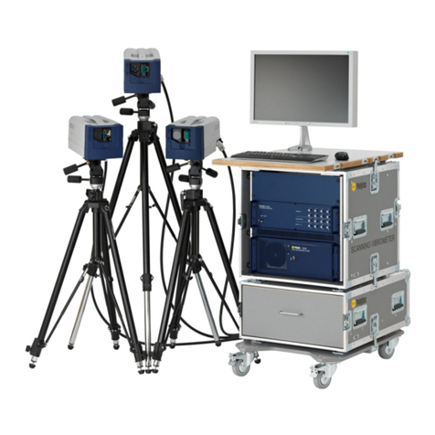
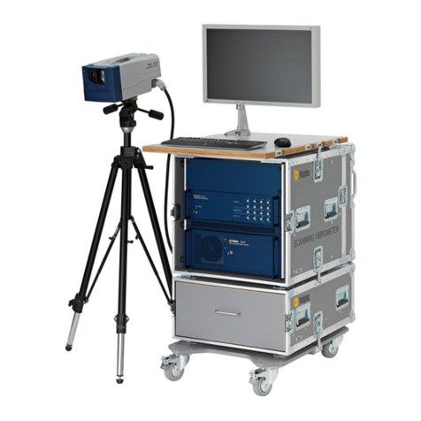
Polytec MSA-600 User manual

Title
Operating Instructions
Micro System Analyzer
MSA-600
Sensor Head MSA-I-620
Front-End MSA-F-620
Controller MSA-E-600
Data Management System MSA-W-620
For MSA-600-X/MSA-600-U Systems

41793-Man-MSA600-X/-U-0322-03en *41793*
Warranty and Service
The warranty for this equipment complies with the regulations in our general terms and
conditions in their respective valid version.
This is conditional on the equipment being used as intended and as described in these
operating instructions.
The warranty does not apply to damage caused by incorrect usage, external mechanical
influences, or by not keeping to the operating conditions. Do not tamper with the instrument or
modify it without authorization as this will invalidate the warranty.
To return the equipment, always use the original packaging. Otherwise, we reserve the right to
check the equipment for transport damage. Mark the package as fragile and sensitive to frost.
Include an explanation of the reason for returning it as well as an exact description of the fault.
You will find information on troubleshooting in these operating instructions.
Trademarks
Brand or product names mentioned in this documentation could be trademarks or registered
trademarks of their respective companies or organizations.
Name Plates
MSA-I-620 Sensor Head MSA-F-620-X/-U Front-End MSA-E-600 Controller
MSA-W-620-X/-U Data
Management System

i
Contents
Contents
1 Safety Information 1-1
1.1 Information on Using these Operating Instructions ............................................................. 1-1
1.1.1 Warning Notices Used .............................................................................................. 1-1
1.1.2 Notices Used ........................................................................................................... 1-1
1.2 Mandatory Signs ................................................................................................................ 1-2
1.3 General Safety Information ................................................................................................ 1-2
1.3.1 Operating the Instrument Safely ............................................................................... 1-2
1.3.2 Intended Use ........................................................................................................... 1-2
1.3.3 User Qualification ..................................................................................................... 1-3
1.3.4 Ambient Conditions .................................................................................................. 1-3
1.3.5 Personal Protective Equipment (PPE) ...................................................................... 1-3
1.3.6 Cleaning ..................................................................................................................1-4
1.3.7 Installing Other Components .................................................................................... 1-4
1.3.8 Disposal ................................................................................................................... 1-4
1.4 Laser Safety ...................................................................................................................... 1-5
1.4.1 Important Warning Notices ....................................................................................... 1-5
1.4.2 Applicable Standards and Directives ........................................................................ 1-6
1.4.3 Equipment ................................................................................................................ 1-6
1.4.4 Information on Laser Class 3R ................................................................................. 1-6
1.4.5 Warning Labels on the Instrument ............................................................................ 1-7
1.5 Lamp Safety ...................................................................................................................... 1-9
1.5.1 Important Warning Notices ....................................................................................... 1-9
1.5.2 Applicable Standards and Directives ........................................................................ 1-9
1.5.3 Equipment ................................................................................................................ 1-9
1.5.4 Information on Risk Category 2 ................................................................................ 1-9
1.5.5 Warning Labels on the Instrument .......................................................................... 1-10
1.6 Electrical Safety ................................................................................................................1-11
1.6.1 Important Warning Notices ......................................................................................1-11
1.6.2 Important Notices ................................................................................................... 1-12
1.6.3 Applicable Standards and Directives ...................................................................... 1-12
1.6.4 Warning Labels on the Instrument .......................................................................... 1-13
1.7 Information on REACH Regulation ................................................................................... 1-13
2 Introduction 2-1
2.1 Area of Application ............................................................................................................. 2-1
2.2 System Summary ............................................................................................................... 2-1
2.3 MSA-600 Options ............................................................................................................... 2-2
2.4 Out-of-Plane-, In-Plane- and Topography Measurements ................................................... 2-3
2.5 Differential Measurements ................................................................................................. 2-3

ii
Contents
3 First Steps 3-1
3.1 Unpacking and Inspection ...................................................................................................3-1
3.2 Control Elements, Displays, and Connections .....................................................................3-4
3.2.1 Sensor Head .............................................................................................................3-4
3.2.2 Front-End .................................................................................................................3-5
3.2.3 Controller ..................................................................................................................3-7
3.2.4 Data Management System .......................................................................................3-8
3.3 Assembly ..........................................................................................................................3-12
3.3.1 Sensor Head ...........................................................................................................3-12
3.3.2 Objective Adapter/Objective Turret ..........................................................................3-13
3.3.3 Objective Positioner (with MSA-A-TMS Option) .......................................................3-14
3.3.4 Holder for Objective Positioner (with MSA-A-TMS Option) ......................................3-16
3.4 Cabling .............................................................................................................................3-19
3.4.1 Connecting the Protective Earth Cable ...................................................................3-21
3.4.2 Connecting the Hardware .......................................................................................3-25
3.4.3 Connecting the Signals ...........................................................................................3-31
3.4.4 Connecting the Mains Cables .................................................................................3-33
3.5 Functional Test .................................................................................................................3-33
3.5.1 Out-of-Plane Vibrations ...........................................................................................3-33
3.5.2 In-Plane Vibrations .................................................................................................3-38
3.5.3 Topography Measurement .......................................................................................3-44
4 Operating 4-1
4.1 Software .............................................................................................................................4-1
4.2 Selecting and Exchanging Objectives .................................................................................4-1
4.3 Overview of the Parfocal Lengths of the Objectives ............................................................4-2
5 Troubleshooting 5-1
5.1 General Tests .....................................................................................................................5-1
5.2 Problems Connecting to the Signal Generator ....................................................................5-3
5.3 Problems Connecting to the Front-End ...............................................................................5-3
5.4 No Laser Beam ...................................................................................................................5-4
5.5 Illumination Module in the Sensor Head does not Light up ..................................................5-4
5.6 Laser Beam is Not Pointing at the Scan Points ...................................................................5-4
5.7 Measurement Signal is Faulty .............................................................................................5-5
5.8 Measurement Takes an Unusually Long Time .....................................................................5-5
6 Technical Specifications 6-1
6.1 Harmonized Standards Applied ...........................................................................................6-1
6.2 MSA-I-620 Sensor Head .....................................................................................................6-1
6.2.1 General Data ............................................................................................................6-1
6.2.2 Optics .......................................................................................................................6-5
6.3 MSA-F-620 Front-End .........................................................................................................6-6
6.3.1 General Data ............................................................................................................6-6
6.3.2 Signal Inputs and Outputs .........................................................................................6-7
6.4 MSA-E-600 Controller .........................................................................................................6-8

iii
Contents
6.5 MSA-W-620 Data Management System ............................................................................. 6-9
6.5.1 General Data ........................................................................................................... 6-9
6.5.2 Industrial PC Configuration ...................................................................................... 6-9
6.5.3 Data Acquisition ....................................................................................................... 6-9
6.5.4 Function Generator (only MSA-600-X) ..................................................................... 6-9
6.6 A-ESG-002 Signal Generator ........................................................................................... 6-10
6.7 Metrological Properties .................................................................................................... 6-10
6.7.1 MSA-600-X/-U ........................................................................................................ 6-10
6.7.2 Topography Measurements .................................................................................... 6-12
Appendix A: Declarations of Conformity
Index

iv
Contents

1-1
1 Safety Information
1.1 Information on Using these Operating Instructions
•
These operating instructions are part of the product. Keep them within
easy reach.
•
Read these operating instructions carefully before operating the
instrument. Pay attention to any documentation provided by other
manufacturers.
•
Make the operating instructions available to the person using the
instrument.
•
If you hand over the instrument, forward the operating instructions to the
next user.
•
If you lose the operating instructions, ask us for a replacement.
1.1.1 Warning Notices Used
The following warning notices are used in these operating instructions and will
give you important advice on how to use the instrument safely:
WARNING!
"Type and source of danger"!
Indicates a dangerous situation or action which could lead to death or serious
injury if this warning is not observed.
» Describes how to avoid the danger.
CAUTION!
"Type and source of danger"!
Indicates a dangerous situation or action which could lead to minor injury if
this warning is not observed.
» Describes how to avoid the danger.
ATTENTION!
"Type and source of danger"!
Indicates a dangerous situation or action which could lead to property
damage if this warning is not observed.
» Describes how to avoid the danger.
1.1.2 Notices Used
In addition, the following notice is used in these operating instructions which
provides additional information on operating the instrument:
INFORMATION
Provides useful notes and information to simplify the operation of the device.

1-2
1 Safety Information
1.2 Mandatory Signs
There is a mandatory sign affixed to the instruments which is briefly explained
in the following:
Figure 1.1: Mandatory sign “Refer to instruction manual”
1.3 General Safety Information
1.3.1 Operating the Instrument Safely
Faultless and safe operation of the instruments presume proper transport and
proper storage, installation and assembly as well as careful operation of the
instruments. In addition, it is imperative for the safe operation of the devices
that you pay attention to the safety and warning notices which are listed in
these operating instructions. When assembling, installing and operating the
instruments, make sure that you adhere to the safety and accident prevention
regulations applicable to the respective application.
1.3.2 Intended Use
The instrument is intended for use in a laboratory. It may only be operated
within the limits set in the specifications. It is not necessary to tamper with the
instruments to use them as intended as this will invalidate the warranty.
Any use other than the one described in these operating instructions is not
permitted. Polytec rejects any liability for damages which occur from improper
use.
The instruments are designed in accordance with good engineering practice
to meet state-of-the-art safety requirements, have been tested, and left the
factory in a condition in which they are safe to operate.

1-3
1 Safety Information
1.3.3 User Qualification
1.3.4 Ambient Conditions
ATTENTION!
Damage to the sensor head caused by impurities!
If dust and other dirt particles from the operating environment penetrate the
instrument, this can cause lasting damage to the instrument.
» Always protect the objective ports on the sensor head with the respective
covers if no objective is mounted.
Operation and
storage
Operate and store the instrument in the ambient conditions as specified in the
technical specifications.
1.3.5 Personal Protective Equipment (PPE)
Task Qualification
Assembly, cabling, adjustment,
operation
The instrument may only be used by qualified personnel
who are familiar with electrical measuring instruments,
have been trained to use the instrument, and have been
instructed on how to work with lasers.
Repair and maintenance The instrument may only be serviced or repaired by the
manufacturer or by qualified personnel authorized by the
manufacturer.
Exchange/installation of
subassemblies
Subassemblies may only be exchanged or installed by
authorized service personnel from Polytec.
PPE For the following work processes Source of danger
Safety shoes - Transport
- Assembly
- Disassembly
Heavy parts

1-4
1 Safety Information
1.3.6 Cleaning
WARNING!
Electric shock caused by penetrating moisture!
If the instruments are live, penetrating moisture can cause an electric shock.
» Switch off the instruments before cleaning them.
ATTENTION!
Damage to the housing surfaces caused by unsuitable cleaning agents!
» Do not use any aggressive solvents such as acetone or ethanol.
1.3.7 Installing Other Components
ATTENTION!
Impairment of the system caused by installing third-party hardware or
software components!
Third party hardware or software components could damage the system or
impair the function of the software.
» To install components which have not been distributed by Polytec, contact
Polytec first.
» Using Windows Update, do not install any optional updates but only
security updates.
» Do not update any installed drivers on your data management system.
» Do not change existing driver settings.
1.3.8 Disposal
Unless otherwise specified, instruments and their components which are
defective or no longer required must be properly disposed in accordance with
the applicable legal provisions.
Component Cleaning agents
Objectives (dust) Soft, lint-free cloth, bellows
Objectives (grease
contamination)
e.g. ethanol or isopropanol
Housing surfaces Mild detergents or disinfectant solutions

1-5
1 Safety Information
1.4 Laser Safety
1.4.1 Important Warning Notices
WARNING!
Eye damage caused by incorrect usage of laser radiation!
» Position the instrument so that the direct or reflected laser beam is not
dangerous.
» Do not look directly into the laser beam.
» Immediately turn away from the laser beam if it hits your unprotected eye.
» For some instruments, exchangeable front lenses are available. Always
mount the front lens first before taking the laser into operation.
» Do not use mirrors or other optical instruments to look into the laser beam.
» If you are working in the laser beam path, do not wear any jewelry and do
not use any tools which may reflect the laser beam and could deflect it into
your eyes.
» If you need to intensively focus for a long time on the target area of the
laser beam for adjustment purposes, wear laser safety eyewear suitable for
the specified laser wavelength.
» Do not use any operating or calibrating equipment other than specified in
these operating instructions and do not perform any other procedures as
this may result in hazardous radiation effect.
» Do not point the laser beam at creatures, when the laser beam could hit in
their unprotected eyes.
» If no measurement object is available, shield the target area of the laser
beam with suitable material so that the laser does not radiate unimpeded
through the room.
» If the instrument has a beam shutter, only open the beam shutter for a
functional test or measurements.
» Store instruments which are not in use in places which unauthorized
persons do not have access to.
» Never open the housing of an instrument which contains the laser unit, as
the laser light of the installed laser often conforms with a potentially
hazardous laser class.

1-6
1 Safety Information
1.4.2 Applicable Standards and Directives
The instrument complies with the standards IEC and EN 60825-1 (Safety of
Laser Products - Equipment Classification and Requirements).
CDRH Compliance Statement
Polytec GmbH confirms that its laser products comply with all applicable
standards and regulations that are set forth by the United States of America's
Health and Human Services (HHS), Food and Drug Administration (FDA),
Center for Devices and Radiological Health (CDRH) for laser products. The
laser products comply with US 21 CFR 1040.10 and 1040.11 except for
conformance with IEC 60825-1 Ed. 3., as described in Laser Notice No. 56,
dated May 8, 2019.
1.4.3 Equipment
Laser
The instrument is equipped with a laser with visible laser radiation.
1.4.4 Information on Laser Class 3R
The properties of laser radiation differ from those of conventional light
sources and are classified accordingly.
•
The emitted optical output power of the laser beam is less than 5 mW
provided the equipment is used in the manner for which it was intended.
This means that the instrument conforms to laser class 3R. It can be
hazardous for the eyes if the laser beam hits the unprotected eye directly.
The skin is not harmed even by the focused laser beam.
•
Instruments that fall into this laser class require additional safety
precautions in the vicinity of the measurement location. These
requirements vary from country to country. In general, at least the black
and yellow laser warning symbols are required at the entrance to the
room, or the area in which the laser system is operating. Inform yourself
about the applicable regulations and standards and, if necessary, contact
your Laser Safety Officer.

1-7
1 Safety Information
1.4.5 Warning Labels on the Instrument
Laser warning
labels
The laser warning labels are shown in the following figure. For countries in the
European Union (EU), labels [2] to [4] are affixed in the language spoken in
the customer's country.
Figure 1.2: Laser warning labels
:DUQXQJ/DVHUVWUDKOXQJ
.ODVVH%ZHQQJH|IIQHW
1LFKWGHP6WUDKODXVVHW]HQ
$XVWULWWV|IIQXQJ
IU/DVHUVWUDKOXQJ
/DVHUVWUDKOXQJ
'LUHNWH%HVWUDKOXQJ
GHU$XJHQYHUPHLGHQ
/DVHU.ODVVH5
1DFK(1
3P:FZȜ QP
:DUQLQJ&ODVV%ODVHU
UDGLDWLRQZKHQRSHQ
$YRLGH[SRVXUHWRWKHEHDP
/DVHU$SHUWXUH
&RPSOLHVZLWK&)5DQG
H[FHSWIRUFRQIRUPDQFHZLWK
,(&(GDVGHVFULEHGLQ
/DVHU1RWLFH1RGDWHG0D\
/DVHU5DGLDWLRQ
$YRLGGLUHFWH\HH[SRVXUH
&ODVV5/DVHU3URGXFW
$FFRUGLQJWR,(&(1
3P:FZȜ QP

1-8

1 Safety Information
Position of laser
warning labels
The position of the laser warning labels on the sensor head (front and back
view) is shown in the following figure.
Figure 1.3: Position of the laser warning labels [1], [2], [3] and [4] as well as the beam exit aperture with the
beam direction [5]
,,,706
"DIUVOH
3FTUTQBOOVOH
"UUFOUJPO
3FTJEVBM7PMUBHF
"DIUVOH
3FTUTQBOOVOH
"UUFOUJPO
3FTJEVBM7PMUBHF
3RO\WHF*PE+3RO\WHF3ODW]
:DOGEURQQ*HUPDQ\
6&$11(5
5()6&$11(5
9,'(2
6<67(0

1-9
1 Safety Information
1.5 Lamp Safety
1.5.1 Important Warning Notices
WARNING!
Damage to eyes caused by high light intensity!
» Do not look directly into the illumination module.
» Do not use any operating or calibrating equipment other than specified
here.
1.5.2 Applicable Standards and Directives
The instrument complies with the standards IEC and EN 62471
(Photobiological Safety of Lamps and Lamp Systems).
1.5.3 Equipment
Illumination
module
The instrument is equipped with an L
ED
-based illumination module.
1.5.4 Information on Risk Category 2
The instrument complies with risk category 2 and poses a low photochemical
risk of retinal damage in the event of direct exposure for > 100 s.
With a duration of < 100 s, the exposure hazard value EHV
1
= 2 at 200 mm
distance from beam exit.
With a duration of < 10000 s, the exposure hazard value EHV = 1 at 1.6 m
distance from the beam exit.
Under any operating conditions, there is no risk to the skin.
1
EHV = the exposure hazard value (EHV) is the relation between exposure level (EL) and the exposure
limit value (ELV). EL = extent of exposure to a source at a specified location for a proven duration. ELV
= maximum exposure level for eye and skin exposure to optical radiation which is not expected to result
in negative biological effects.The EHV is greater than 1 when the exposure level exceeds the exposure
limit value.

1-10
1 Safety Information
1.5.5 Warning Labels on the Instrument
Warning labels
The lamp warning label is shown in the following figure. For countries in the
European Union (EU), the warning label is affixed in the language spoken in
the customer's country.
Figure 1.4: Lamp warning label
Position of lamp
warning label
The position of the lamp warning label on the sensor head is shown in the
following figure.
Figure 1.5: Position of the lamp warning label [1] as well as the beam exit aperture with the
beam direction [2]
!"#$
!%&'
(!#)
* %+
,
(-./
0!!
1#'
%#23#
'/!#%
*+
,,,706

1-11
1 Safety Information
1.6 Electrical Safety
1.6.1 Important Warning Notices
WARNING!
Fire risk caused by inaccessible or missing disconnection device!
A fire risk exists in case of overheating, e.g. due to a device fault.
Furthermore, touching hot housing parts can cause burns. The mains switch
disconnects the device from the power supply and is used to switch it off in
case of danger. If the mains switch is not freely accessible, use the mains
plug to disconnect the device in case of danger.
» Always keep the mains switch or respectively mains plug freely accessible.
» If you can keep neither the mains switch nor the mains plug freely
accessible, install an additional disconnection device.
WARNING!
Fire risk caused by wrong fuses!
» Replace defective fuses only by fuses of the same kind with the amperage
given on the instrument.
WARNING!
Electric shock caused by missing protective earth cable!
In the case of a fault, missing or improperly connected protective earth cables
can lead to dangerous voltages that cause an electric shock when the devices
are touched.
» Before operating the measurement system, always connect the protective
earth cables of the controller, the objective positioner (with MSA-A-TMS
option) and the sensor head as described in S
ECTION
3.4.1.
» Make sure that the contact resistance is < 0.1 Ωat 25 A at all connection
points relevant for the assembly of the protective earth cables.
» Never remove the protective earth cables during operation.
WARNING!
Electric shock caused by dangerous voltage and residual charge on
piezo actuators!
Piezo actuators are installed both in the sensor head and in the objective
positioner (with MSA-A-TMS option). Temperature changes and compressive
stresses can induce charges in piezo actuators. If the equipment is under
voltage or residual voltage, touching the cable connections or short-circuiting
the contacts can lead to an electric shock (120 VDC max.).
» Do not remove any connection cables from the sensor head during
operation.
» Do not touch the contacts of the device plugs or connecting plugs.
» Always turn off the devices and wait some time before removing the
connecting cables.
» Secure the connection plugs on the sensor head against accidental
disconnection.

1-12
1 Safety Information
ATTENTION!
Damage to the device caused by insufficient opportunity for air
circulation!
Inside the device, heat is generated during operation. If the heat cannot
escape from the housing, a heat accumulation is being caused. This will
overheat the electronic parts inside the device and may result in a defect.
» Always keep free all air inlets and outlets of the device.
» Keep at least 50 mm distance to the wall when you set up the device.
» If the devices are in a system cabinet: Remove all covers of the system
cabinet before switching on the devices.
» If you notice a cooling fan failure, turn off the instrument immediately and
contact your local Polytec representative if necessary.
1.6.2 Important Notices
INFORMATION
The instrument is subject to Limit Class A and can cause radio interferences
with electrical devices in residential areas.
Take appropriate precautions to prevent these adverse effects.
1.6.3 Applicable Standards and Directives
Protection class
The instrument complies with the electrical protection class 1 according to
EN 61140. That means when the instrument is used as intended and
connected to the power supply correctly, exposure to electric current is
prevented by the closed, grounded metal housing.
Low voltage
The instrument is subject to the EU Directive 2014/35/EU (Low Voltage
Directive). With the CE marking Polytec confirms that the provisions of the
standards the directive is based on and that are applicable to the product are
fulfilled.
EMC
The instrument is subject to EU Directive 2014/30/EU (EMC Directive) and
therefore conforms with the limits for emission and immunity specified in the
standards it is based on. With the CE marking Polytec confirms that the
instrument has been tested successfully.
RoHS
The instrument is subject to EU Directive 2011/65/EU (RoHS) on the
restriction of the use of certain hazardous substances in electrical and
electronic equipment. With the CE marking Polytec confirms that the
provisions of the standard the directive is based on are fulfilled.

1-13
1 Safety Information
1.6.4 Warning Labels on the Instrument
The warning label is shown in the following figure.
Figure 1.6: Warning of residual voltage
1.7 Information on REACH Regulation
Information on the Duty to Register
Regulation (EC) No 1907/2006 of the European Parliament and of the Council
concerning the Registration, Evaluation, Authorization and Restriction of
Chemicals (REACH) regulates the manufacturing, placing on the market and
using chemical substances and products derived therefrom. We are a
manufacturer of measurement systems. According to the REACH regulation,
these products are considered as articles and therefore not subject to
registration.
Communication of Information on Substances in Articles
According to Article 33 of the REACH Regulation, suppliers of articles must
inform their customers if the delivered article contains a substance from the
REACH candidate list (SVHC list) in a concentration above 0.1 percent per
weight. On June 27, 2018, lead (CAS: 7439-92-1/EINECS: 231-100-4) was
added to the SVHC candidate list. This addition triggers a related information
obligation in the supply chain.
We hereby inform you that components of our products may be made of
copper alloys containing lead in concentrations above 0.1 percent per weight.
As lead is firmly bound as an alloying component, and therefore no exposure
is to be expected, no additional information on safe usage is required. Our
products are tested for handling, usage or recycling, and there is no risk if all
relevant technical specifications and directives are met. The hazardous
substance classification, the rules for safe handling of lead metal, and the
range of applications for our products remain unchanged. Refer to these
operating instructions for safe handling of our product.

1-14
1 Safety Information
This manual suits for next models
2
Table of contents
Other Polytec Measuring Instrument manuals

Polytec
Polytec TMS-350 TopMap In.Line User manual

Polytec
Polytec TMS-500 TopMap Pro.Surf User manual

Polytec
Polytec OFV-3001 User manual

Polytec
Polytec OFV-3001 User manual

Polytec
Polytec PSV-500 User manual

Polytec
Polytec PSV-500-3D User manual

Polytec
Polytec PSV 300 User manual

Polytec
Polytec PDV-100 User manual
Popular Measuring Instrument manuals by other brands

Swan Analytical Instruments
Swan Analytical Instruments AMI Soditrace Operator's manual

ATI Technologies
ATI Technologies Q45CT O & M Manual

Geotech
Geotech Biogas operating manual

Spacetronik
Spacetronik SP-OSM32 user manual

ZURN
ZURN ZEG6003EV Installation, operation, maintenance and parts manual

luxvision
luxvision LM-7800 Operation manual