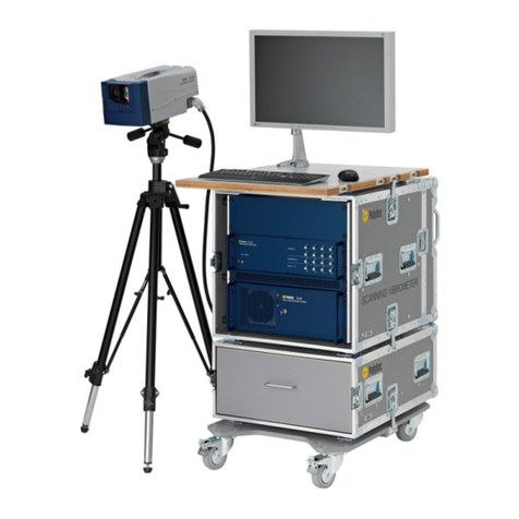
Polytec TMS-350 TopMap In.Line User manual

Title
Hardware Manual
3D Topography Measurement
System
TMS-350 TopMap In.Line
Interferometer TMS-I-350
Controller TMS-E-350
PC TMS-W-350

41671-Man-TMS350-TopMap-InLine-1015-01en *41671*
Warranty and Service
The warranty for this equipment complies with the regulations in our general terms and
conditions in their respective valid version.
This is conditional on the equipment being used as intended and as described in this manual.
The warranty does not apply to damage caused by incorrect usage, external mechanical
influences or by not keeping to the operating conditions. The warranty also is invalidated in the
case of unauthorized manipulation or modification of the equipment.
To return the equipment always use the original packaging. Otherwise we reserve the right to
check the equipment for transport damage. Please mark the package as fragile and sensitive to
frost. Include an explanation of the reason for returning it as well as an exact description of the
fault. You will find information on troubleshooting in this manual.
Trademarks
Brand or product names mentioned in this manual could be trademarks or registered
trademarks of their respective companies or organizations.
Name Plates
TMS-I-350 Interferometer TMS-E-350 Controller TMS-W-350 PC

i
Contents
Contents
1 Safety Information 1-1
1.1 Information on Using this Manual ....................................................................................... 1-1
1.1.1 Warning Notices Used .............................................................................................. 1-1
1.1.2 Notices Used ........................................................................................................... 1-1
1.2 General Safety Information ................................................................................................. 1-2
1.2.1 Operating the Instrument Safely................................................................................ 1-2
1.2.2 Intended Use ............................................................................................................ 1-2
1.2.3 User Qualification...................................................................................................... 1-2
1.2.4 Ambient Conditions ................................................................................................... 1-3
1.2.5 Transport ..................................................................................................................1-3
1.2.6 Personal Protective Equipment ................................................................................. 1-3
1.2.7 Cleaning ...................................................................................................................1-3
1.2.8 Installing other Components ..................................................................................... 1-4
1.2.9 Disposal.................................................................................................................... 1-4
1.3 Lamp Safety ...................................................................................................................... 1-4
1.3.1 Important Warning Notices ........................................................................................ 1-4
1.3.2 Applicable Standards and Directives ......................................................................... 1-4
1.3.3 Equipment................................................................................................................. 1-5
1.4 Electrical Safety ................................................................................................................. 1-6
1.4.1 Important Warning Notices ........................................................................................ 1-6
1.4.2 Applicable Standards and Directives ......................................................................... 1-7
2 Introduction 2-1
2.1 System Overview ............................................................................................................... 2-1
2.2 Operating Principle ............................................................................................................ 2-2
3 First Steps 3-1
3.1 Unpacking and Inspection ................................................................................................... 3-1
3.2 Control Elements, Displays and Connections ..................................................................... 3-3
3.2.1 Controller .................................................................................................................. 3-3
3.2.2 TMS-I-350 Interferometer ......................................................................................... 3-5
3.2.3 TMS-W-350 PC ......................................................................................................... 3-8
3.3 Assembly .......................................................................................................................... 3-10
3.3.1 Assembling or Exchanging the Desiccant Cartridge .................................................3-11
3.3.2 Assembling the Interferometer ............................................................................... 3-12
3.4 Cabling ............................................................................................................................ 3-12
3.5 Functional Test ................................................................................................................. 3-16
4 Measuring 4-1
4.1 Making a Measurement with the Instrument ....................................................................... 4-1
4.2 Making High-precision Measurements ............................................................................... 4-2
4.3 Reference Filter Exchange ................................................................................................. 4-3

ii
Contents
5 Troubleshooting 5-1
5.1 General Tests .....................................................................................................................5-1
5.2 Problems with the Interferometer ........................................................................................5-2
6 Technical Specifications 6-1
6.1 Harmonized Standards Applied ...........................................................................................6-1
6.2 TMS-E-350 Controller .........................................................................................................6-1
6.3 TMS-I-350 Interferometer ...................................................................................................6-2
6.3.1 General Data ............................................................................................................6-2
6.3.2 Optics .......................................................................................................................6-4
6.4 TMS-W-350 PC ..................................................................................................................6-6
Appendix A: TMS-A-305 Calibration Set
Appendix B: Declaration of Conformity
Index

1-1
1 Safety Information
1.1 Information on Using this Manual
•
This manual is part of the product. Keep it within easy reach.
•
Read this manual carefully before operating the instrument. Pay attention
to any provided manuals from other manufacturers.
•
Make the manual available to the person using the instrument.
•
If you pass on the instrument, also pass on the manual to the next user.
•
If you should lose the manual, please ask us for a replacement.
1.1.1 Warning Notices Used
The following warning notices are used in this manual and will give you
important advice on how to use the instrument safely.
WARNING!
"Type and source of danger"!
Indicates a dangerous situation or action which could lead to death or serious
injury if this warning is not noticed.
» Describes how to avoid the danger.
CAUTION!
"Type and source of danger"!
Indicates a dangerous situation or action which could lead to minor injury if
this warning is not noticed.
» Describes how to avoid the danger.
ATTENTION!
"Type and source of danger"!
Indicates a dangerous situation or action which could lead to property
damage if this warning is not noticed.
» Describes how to avoid the danger.
1.1.2 Notices Used
In addition, the following notice is used in this manual which provides
additional information on operating the instrument:
INFORMATION
Gives useful notes and information to simplify the operation of the device.

1-2
1 Safety Information
1.2 General Safety Information
1.2.1 Operating the Instrument Safely
Faultless and safe operation of the instrument presume proper transport and
proper storage, installation and assembly as well as careful operation of the
instrument. In addition, it is imperative for the safe operation of the device that
you pay attention to the safety and warning notices which are listed in this
manual. When assembling, installing and operating the instrument, make sure
that you adhere to the safety and accident prevention regulations applicable
to the respective application.
1.2.2 Intended Use
The instrument is intended for use in a laboratory. It may only be operated
within the limits set in the technical specifications. Tampering with the
instruments in any way is not necessary when using the equipment as
intended and will invalidate the warranty.
Any use other than the one described here and in S
ECTION
2.1 is not
permitted.
The instruments are designed in accordance with good engineering practice
to meet state-of-the-art safety requirements, have been tested, and left the
factory in a condition in which they are safe to operate.
1.2.3 User Qualification
Task Qualification
Assembly, adjustment, operation This instrument may only be used by qualified personnel
who are familiar with electrical measuring instruments and
have been trained to use the instrument.
Repair and maintenance This instrument may only be maintained by the
manufacturer or by qualified persons who have been
authorized by the manufacturer.
Exchange/Installation of
subassemblies
Subassemblies may only be exchanged or installed by
authorized service personnel from Polytec.

1-3
1 Safety Information
1.2.4 Ambient Conditions
Operation and
storage
Operate the instrument in the ambient conditions as specified in the technical
specifications.
ATTENTION!
Optics impaired by condensation!
If the instrument is started up in a warm environment after being stored in a
cold environment, this can cause condensation which impairs the optical
components.
» Wait with the start-up of the device until the temperature of the device
adapted to the ambient temperature.
1.2.5 Transport
CAUTION!
Risk of injury caused by heavy system components!
There is the risk of injury to hands and feet when carrying and lifting heavy
system components.
» Only lift system components in pairs or using a suitable lifting device.
» Wear safety shoes.
» Wear protective gloves.
1.2.6 Personal Protective Equipment
1.2.7 Cleaning
WARNING!
Electric shock caused by penetrating moisture!
If the instrument is under voltage, moisture penetrating can cause an electric
shock.
» Always disconnect the mains plug before you clean the device.
ATTENTION!
Damage to the housing surfaces caused by unsuitable cleaning agents!
» Do not use any aggressive solvents such as acetone or ethanol.
Source of danger Personal protective equipment
Heavy parts (transport, setup) Safety shoes
Component Cleaning agent
Exit window (dust) Soft, lint-free cloth; bellows
Exit window (grease) e.g. ethanol or isopropanol
Housing surfaces Mild detergent or disinfectant solutions

1-4
1 Safety Information
1.2.8 Installing other Components
ATTENTION!
Impairment of the system caused by installing third-party hardware or
software components!
Off-system hardware or software components could damage the system or
impair the function of the software.
» If you want to install components which have not been distributed by
Polytec, please contact Polytec first.
ATTENTION!
Damage of the devices caused by wrong combination of devices!
The individual devices are synchronized.
» Always combine only synchronized devices
1.2.9 Disposal
Instrument
Unless otherwise specified, defective or no longer required instruments and
their components must be properly disposed in accordance with the
applicable legal provisions.
1.3 Lamp Safety
1.3.1 Important Warning Notices
WARNING!
Damage to eyes caused by high light intensity!
» Do not look directly into the illumination module.
» Do not use any operating or calibrating equipment other than specified
here.
1.3.2 Applicable Standards and Directives
Polytec instruments generally comply with the standards of IEC and
EN 62471 (Photobiological Safety of Lamps and Lamp Systems).

1-5
1 Safety Information
1.3.3 Equipment
LED
The instrument is equipped with a light emitting diode (LED) as the light
source, complies with risk category 1 and poses a low photochemical risk of
retinal damage in the event of direct exposure for > 100 s. Exposure hazard
value (EHV) with a duration of < 100 s: 0.24 at 50 mm distance to the beam
exit.
1
There is no risk to skin under any operating conditions.
Safety
equipment
The LED is switched on using the mains switch on the device.
Beam exit
aperture
The position of the beam exit aperture on the instrument is shown in the
following figure.
Figure 1.1: Position of beam exit aperture
1
EHV = the exposure hazard value (EHV) is the relation between exposure level (EL) and the exposure
limit value (ELV). EL = extent of exposure to a source at a specified location for a proven duration. ELV
= maximum exposure level for eye and skin exposure to optical radiation which is not expected to result
in negative biological effects. The EHV is greater than 1 when the exposure level exceeds the exposure
limit value.
Beam

1-6
1 Safety Information
1.4 Electrical Safety
1.4.1 Important Warning Notices
WARNING!
Fire risk caused by inaccessible or missing disconnection device!
A fire risk exists in case of overheating, e.g. due to a device fault.
Furthermore, touching hot housing parts can cause burns. The mains switch
disconnects the device from the power supply and is used to switch it off in
case of danger. If the mains switch is not freely accessible, use the mains
plug to disconnect the device in case of danger.
» Always keep the mains switch or respectively mains plug freely accessible.
» If you can not keep neither the mains switch nor the mains plug freely
accessible, install an additional disconnection device.
WARNING!
Electric shock caused by applied voltage!
» Always disconnect the instrument from the power before you are
maintaining or cleaning it.
WARNING!
Fire risk caused by wrong fuses!
» Replace defective fuses only by fuses of the same kind with the amperage
given on the instrument.
ATTENTION!
Damage of the device caused by insufficient opportunity for air
circulation!
Heat is created inside the device during operation. If the heat can not exhaust
from the housing it leads to heat accumulation. This will overheat the
electronic parts inside the device and may result in a defect.
» Always keep free all air inlets and outlets of the device.
» Keep at least 50 mm distance to the wall if required when you set up the
device!
» If the devices are in a system cabinet: Remove all covers of the system
cabinet before switching on the devices.
» If you notice a cooling fan failure, switch off the device immediately.

1-7
1 Safety Information
1.4.2 Applicable Standards and Directives
The instrument complies with the electrical protection class 1 in accordance
with the EU Directive 2006/95/EC (Low Voltage Directive). That means, with
correct mains connection and intended use, exposure to electric current is
prevented by the closed, grounded metal housing.
The device is subject to EU Directive 2004/108/EC (EMC Directive) and
therefore complies with the limit values for emission and immunity of the
standards it is based on (refer also to S
ECTION
6.1). Being awarded the CE
mark confirms that Polytec has ensured that the instrument has been tested
successfully.

1-8
1 Safety Information

2-1
2 Introduction
2 Introduction
2.1 System Overview
The TMS-350 is a 3D topography measurement system for optical, non-
contact acquisition of the structure of rough and also reflective surfaces.
The TMS-350 measurement system is shown in the following figure:
Figure 2.1: System components of the TMS-350
Sensor head
Controller
PC Monitor

2-2
2 Introduction
2.2 Operating Principle
The TMS-350 is based on the principle of the white-light interferometer. In
one interferometer arm the test sample is fixed in position, in the other there
is a reference mirror. The reference mirror is moved with the aid of a piezo. A
camera depicts the test sample. The captured image is superimposed with the
reference mirror. Interference will only occur if the optical path length
difference between the reference mirror and the corresponding points on the
test sample is zero. During this measurement run, depending on the
topography of the test sample, the software finds interferences pixel by pixel.
Once the predefined distance has been traveled, the topographical structure
of the test sample is digitalized. The results can be evaluated on the screen
with the aid of numerous functions in the TMS software. The export function
and the automation interface also allow an evaluation of the topography data
with other applications.
Figure 2.2: Schematic design of the interferometer

3-1
3 First Steps
3 First Steps
3.1 Unpacking and Inspection
INFORMATION
The components marked with an (*) are described in detail in separate
manuals!
Always pay attention to these manuals, too!
Unpacking
The scope of supply includes the following components:
•
TMS-I-350 interferometer
•
TMS-E-350 controller
•
TMS-W-350 industrial PC
•
Keyboard and mouse
•
TFT monitor with power supply and mains cable
•
Supply cable (Supply)
•
Special Ethernet cable for the connection of the camera
•
Piezo cable from the controller to the interferometer (Piezo)
•
2 mains cables
•
TMS-A-301, TMS-A-302, TMS-A-303 or TMS-A-304 reference filter
•
2 desiccant cartridges
•
TMS software
•
Hardlock (dongle)
Optional:
•
TMS-A-301 (100%) reference filter
•
TMS-A-302 (12%) reference filter
•
TMS-A-303 (2.5%) reference filter
•
TMS-A-304 (0.15%) reference filter
•
Torx® screwdriver (size TX10)
•
λ/20 plate
•
TMS-A-305 calibration set
•
A-STD-TST-01 stand
•
A-STD-TST-300 stand

3-2
3 First Steps
Inspection
Pay attention to the following steps when unpacking:
1. Check the packaging for signs of unsuitable handling during transport.
2. After unpacking, check all components for external damage (scratches,
loose screws, damaged components, etc.).
3. In the case of a wrong delivery, damage or missing parts, immediately
inform your local Polytec representative, stating the serial numbers of the
instruments. The serial number can be found on the name plate. You will
find the name plate on the instruments as well as on the inside cover of
this manual.
4. Carefully retain the original packaging in case you have to return the
instruments.

3-3
3 First Steps
3.2 Control Elements, Displays and Connections
3.2.1 Controller
Front view
The front view of the controller is shown in the following figure.
Figure 3.1: Front view of the controller
1
L
ED
POWER
indicator
L
ED
lit up: ready to operate
2I/O
mains switch
TMS-350
CONTROLLER
POWER
1
2

3-4
3 First Steps
Back view
The back view of the controller is shown in the following figure.
Figure 3.2: Back view of the controller
1
Cooling fan
2
Warning label
3
Name plate
Plate with information on model, serial number, power specifications, etc.
4POWER
mains connection (socket for standard power cord with built-in fuses)
5 SUPPLY SENSOR
connector (7-pin circular jack)
Connection for the supply cable to the interferometer for the interferometer mains
supply
6
USB interface (Universal Serial Bus, type B)
Connector to connect the piezo controller with the PC
7
Connector
PIEZO SENSOR
(Sub-D jack with two coaxial applications)
Connection for the piezo control cable (Piezo Control) from the controller to the
interferometer to control the piezo
1
7
3
654
2
-20...+120V
PIEZO SENSOR
SUPPLY SENSOR
POWER
WARNING !
Disconnet Mains
before opening
ACHTUNG !
Vor dem Öffnen
Netzstecker ziehen

3-5
3 First Steps
3.2.2 TMS-I-350 Interferometer
Front view
The front view of the interferometer is shown in the following figure.
Figure 3.3: View of the interferometer
1
Reference filter
Filter to adjust the intensity of the reference light to the intensity of the object
light.
2
Beam exit window
1
2

3-6
3 First Steps
Back view
The back view of the interferometer is shown in the following figure.
Figure 3.4: Back view of the interferometer
1
Name plate
Plate with information on model, serial number, power specifications, etc.
2
Holder desiccant cartridge
3 PIEZO SENSOR
connector (Sub-D jack with two coaxial applications)
Connection for the piezo cable (Piezo) from the controller to control the piezo
4VIDEO
connection
Connection for the video camera cable (Ethernet) from the PC to control the
video camera and transmit the video signals
5 SUPPLY SENSOR
connector (7-pin circular jack)
Connection for the supply cable from the controller for the interferometer mains
supply
SUPPLY SENSOR VIDEO PIEZO SENSOR
12
543
This manual suits for next models
3
Table of contents
Other Polytec Measuring Instrument manuals