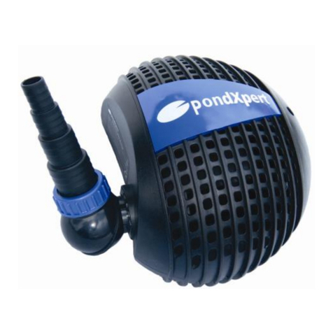
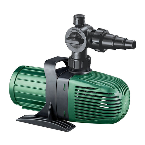
PondXpert VariFlow PXVF10000 User manual

42/52000
VariFlow 10000 / 20000 / 30000/ 42000/ 52000
OWNER’S MANUAL
Introduction
Congratulations on your purchase of one of the most advanced technological pumps
on the market. With PondXpert VariFlow you have full control over the water flow
from your pump.
The pumps are carefully inspected and tested to ensure both safety and operating
performance. However, failure to follow the instructions and warnings in this manual
may result in pump’s damage and/or serious injury. Be sure to read and save this
manual for future reference.
Performance Parameters Table
Model No:
Control
Box
(W)
Max
Power
Watts
Max
Flow
(L/H)
Max
Head
(Mtr)
Min
Flow
(L/H)
Min
Power
Watts
Hose Tail
Fittings
PXVF10000
100W
85W
9200
5.0m
4400
15W
20/25/32/38
PXVF20000
200W
187W
19800
7.0m
9300
34W
25/32/38/50
PXVF30000
400W
385W
30000
10.0m
12000
45W
25/32/38/50
PXVF42000
450W
450W
42000
6.5m
32060
105W
3”Outlet
PXVF52000
600W
600W
52050
8.5m
30658
180W
3” Outlet
All pumps voltage: AC220-240V 50/60Hz.
2m power cord to LCD controller unit then 8m power cord to pump.
Control and Panel Function
LED figures on LCD screen indicates the wattage output going to the pump.
There are three buttons located on the control panel with the following functions:
Pump ‘On’ or ‘Stop
Slow water flow (reduce power)
Increase Flow (increase power)

Operating instructions
After first attaching power to the unit a Power setting is revealed on LED display
(‘PXXX’in red digitals).
“P”is short for “power” and this is how much power is going through to the pump in
watts. When slow/fast button is pressed the “Flow” or ‘F’ setting is revealed –there
are 70 flow settings from 030 to 100. Press Slow or Increase to reveal setting, press
again in quick succession to change setting by one level, leave finger on button for
rapid increase/decrease.
Led Protection Mode
To protect the LED Screen after 30 seconds without touch the LED changes from micro
bright to the screen saver mode; Press any button to return to normal.
Memory Function
Control Panel stores the last setting used. It will retune to this setting when re-
connected.
Fault Code Description
Using intelligent circuitry, the control panel will sense any pump malfunction and will
return an error code to the LCD display for viewing. We include suggested remedies.
Er01: Abnormal working current; Check if pump short of voltage or controller broken
Er02: Controller over-heating; Check if Controller positioned in sun or high temperature
Er03: Pump idling;Check the Pump works dry.
Er04: The impeller stopped turning; Clean Pump & Impellor until impellor turns freely.
Er05: Abnormal running voltage; Check input supply voltage.
Auto-Off Function
Should your pond or water reservoir become too shallow for the pump to operate
correctly sensors built into the pump will detect this. After a period of two minutes
unless this situation is rectified, the pump will switch off automatically to prevent
motor damage.
Methods of Use
Your pump must always be immersed in water before it is switched on. The pump can
be submersed or run externally. In “dry”use water flow should be connected to the
water intake hose. As the name implies an external pump sits outside of the pond in a
dry location.

Fig. A) VariFlow Submerged Fig. B) VariFlow Dry Mounted
Pump can be positioned underwater (fig. A) or dry-mounted (Fig. B)
General safety Instructions
Read and observe all of the instructions clearly before installing, connecting and
operating the pump. Make sure the pump is securely and correctly installed before
switching on.
Always disconnect the pump when not in use and when carrying out maintenance.
Always disconnect all equipment in the pond before starting to handle, maintain,
repair or install any pond equipment.
The appliance is not intended for use by persons (including children) with reduced
physical, sensory or mental capabilities, or lack of experience and knowledge, unless
they have been given supervision or instruction concerning use of the appliance by a
person responsible for their safety.
Children should be supervised to ensure that they do not play with the appliance.
For safety reasons, servicing or repair of this item should only be carried out by
PondXpert.
Never hang or carry the pump by the power cord.
Do not operate the pump with a damaged cord or plug. The supply cord of the
appliance cannot be replaced.
If the electrical cord is damaged the product should be scrapped.
Safety and Electrical Connections
This unit is designed for outdoor use only. Take care to ensure that you can easily lift
your pump out of the water for routine maintenance. If this is necessary do not pick
your pump up by the electrical cable but by the main body/ cage of the pump.
Always disconnect all equipment in the pond before starting to handle, maintain,
repair or install any pond equipment.
The pump is electrically operated so great care must be taken during installation and
operation. The following electrical and safety guidelines must be carefully followed.
Each pump is supplied with an 8 metre length of 3 core electrical cable which is
permanently connected to the pump.
Safe Operation Conditions
The pump maximum operating depth is 1.5 meters. (2m for 42/52000).
Pump can handle solid particles up to 6mm.
Pump can be used in salt or freshwater conditions.
The LCD Control Unit is weatherproof and there are four slots on the unit to provide
the opportunity for wall fastening. For longer life it is advised that the unit is sheltered
and protected as much as possible from the weather to prevent UV damage or water
ingress.

Pump –Electrical Safety
Each pump is supplied with a 8metre length of 3 core electrical cable which is
attached to the Control Unit via a plug-in connector. A 2m length of permanently
attached power cable runs from the connector to the mains supply.
The termination to the mains supply should be permanent, inside a dry weatherproof
enclosure, through a double pole switched fused spur with a minimum contact gap of
3mm –(disconnected) to BS 3676 –and fitted with a 3 or 5 amp fuse.
Exposed cable runs should be sensibly positioned, and protected if necessary, by
armoured conduit.
A 10mA or 30mA Residual Current Circuit Breaker (RCD) MUST be fitted to the mains
supply.
Permanent installations to the mains supply (hard wiring) must comply with the
regulations of the local electricity authority which may stipulate the use of metal or
plastic conduit to protect the cable.
If in any doubt about wiring to the mains supply contact a qualified electrician or your
local electricity authority.
Protect from frost. In cold winter weather (when fish are inactive and algae growth
ceases) the pump may be switched off. It should then be drained of water, removed
(if possible) from its installation and stored in a dry, frost-protected area.
Directions for use
Installation
Once installed the pond water will flow through the pump as the pump’s impellor
draws in water. It is always best to position your pump at the opposite end to where
the water returns to the pond to provide maximum circulation.
10000, 20000, 30000
Your pond is supplied with a hosetail. This should be screwed into the threaded pump
inlet. Pond hose size 20-50mm (3/4” to 2”) can be attached to the inlet hosetail
The wires in the mains electrical lead are coloured in accordance with the
following code:
BLUE –Neutral (marked with an “N” in most terminal connections)
BROWN –LIVE (marked with an “L” in most terminal connections)
GREEN/YELLOW –EARTH (marked “E” or in most terminal connections)
1st January 2005 revised Building Regulations for England and Wales
Installing this product in the garden is classified as ‘notifiable’. The
Regulations now require you to tell your local authority building control
department that you intend to install this product before installation. Your
local authority will let you know how you can get your installation approved

(depending on model). Cut the inlet hose to the size appropriate to the size of hose
you are using. Then connect the hose from your pump to your filter system or position
it where you want the water to return. Ensure a watertight seal by the use of hose
clips.
42000, 52000
Pump is supplied without a hosetail or filter cage. Retailer to supply separately.
MAINTENANCE
To clean the pump, remove the back cover, sealing cover and the rotor/impeller.
Use a small brush or stream of water to remove any debris. Note: pump shaft can not
be removed. If the pump does not work, check the following:
- Check the circuit. Please try unit on another power socket.
- Check the pump outlet and tube. Algae and dirt may block them up
- Check the inlet to ensure not clogged by debris.
- Remove the pump inlet to access the impeller. Turn the rotor to check if broken or
jammed.
- Monthly maintenance prolongs your pump’s life. Clean rotor, remove the dirt. etc
NOTE: Ensure the electrical cord loops below the power socket like a “Drip Loop”. It
will prevent the water from running around the cable into the power socket
Limited Warranty
This product is guaranteed for a period of 36 months (excluding rotor assembly) from
the date of purchase for material or manufacturing defects. The guarantee covers the
substitution of defective parts. However, the guarantee is considered null and void in
the case of improper use, improper handling or negligence on the part of the buyer. If
your pondXpert pump fails please take it back to the retail outlet from where it was
purchased. You will be required to take your receipt/proof of purchase with you. This
does not affect your statutory rights.

PondXpert
A3 Bentley Avenue
Billingham
TS23 4BU
UK
01642 370898
www.pondxpert.co.uk
Your appliance
contains valuable
materials which can
be recovered or
recycled. Leave it at
a local civic waste
collection point.
This manual suits for next models
4
Table of contents
Other PondXpert Pond Pump manuals
Popular Pond Pump manuals by other brands
Messner
Messner system-N 850 operating instructions

Oase
Oase PondJet Eco operating instructions

Profi-pumpe
Profi-pumpe Rügen operating instructions

HEISSNER
HEISSNER F540-00 Instructions for use
Pond Technics
Pond Technics POND AIR 600 manual

Tsurumi Pump
Tsurumi Pump AquascapePro 8-PN 5500 Instructions & maintenance
