PoolPak PPK070 - 100 User manual

Dehumidifiers
PPK‐070toPPK‐530
Indoor/OutdoorModel
OperationandMaintenanceManual
PoolPakLLCPoolPak.com

B–TableofContent
OMM.B.P.AA.00
B‐
1
June
2018
TableofContent
ChapterC‐GeneralInformation C–1
OperatingSafety
C–1
ReferenceandAdditionalInformation
C–2
o
ContactUs
C–2
BasicInformation
C–3
o DehumidifierViewandOptions
C–3
o
DehumidifierExternalSystemsConnection
C–5
o DehumidifierOptionalArrangement
C–5
o AirConditioningOptions–OutdoorAirFluidCoolers
C–6
o
EquipmentSpecificData
C–8
ChapterD‐LayoutandComponents D–1
DehumidifierMainComponents
D–1
ControlSystem
D–4
OutdoorAirFluidCoolerLayoutandComponents
D–5
ChapterE‐SequenceofOperation E–1
SetPoints
E–1
Ventilation
E–1
o PurgeOption
E–1
o HeatRecoveryOption
E–2
SpaceHeating
E–2
AirConditioning,DehumidificationandPoolHeating
E–2
o EconomiserModeOption
E‐2
o Compressor(s)
E–3
ChapterF‐InterfaceandCommunication F–1
TouchDisplayOperatorPanel
F–1
o AlarmsF–2
RemoteCommunication
F–3
ChapterM‐BasicMaintenance M‐1
MaintenanceandSafety
M–1
MaintenanceKeyPoints
M–1
RoutineMaintenanceProgram
M–2
SpecificComponentsMaintenance
M–3
ChapterW‐Warranty W–1

B–TableofContent
B‐
2
Thispageisleftblank

C–GeneralInformation
OMM.C.P.AA.00
C‐
1
June
2018
GeneralInformation
Thismanualprovidesbasicinformationabouttheapplicabledehumidifieranditsoperation.
Importantinformationregardinginstallation,maintenance,andstartupaswellasadditionalandauxiliarysystems
anddevices(outdoorcondenser,communicationinterfaces,etc.)isnormallyprovidedwiththedehumidifierand
canalsobeobtainedatfactory(seeContactUsbelow).
OperatingSafety(Warnings,Cautions,andNotes)
FORYOURSAFETY:READBEFOREPERFORMINGANYOPERATIONS,MAINTENANCEORSERVICETASKS!
Onlyqualifiedtechniciansshouldinstall,operate,maintainorservicemechanicalequipment
includingcurrentdehumidificationsystem.
Makesuretoreadthismanualbeforeperforminganytaskstofamiliarizeyourselfwiththe
equipmentaswellaswithanypotentialhazards.Alwaysexercisecaution!
Bewareofelectricalpowerandhighelectricalvoltage!
• Followpropersafetyprocedures–lockout,tagout,andotherrespectiveprocedures
• Failuretofollowsafetyprocedurescanresultinseriousinjuryordeath
Bewareofmovingpartsandhotsurfaces!
• Makesuretostopallmovingparts(fans,blowers,etc.)beforeaccessingtheequipment’s
internalspace
• Beawareofhotsurfaces(hotrefrigeration,spaceheatingpipes,coils,heaters,etc.)
Bewareofhighpressuresandchemicals!
• Dehumidifiers,equippedwithcompressors,containrefrigerantunderhighpressure;oilis
alsocontainedinthecompressorandrefrigerationcircuit(s)
• Somedehumidifiersmayalsocontainotherliquidssuchasglycolmixturesandpoolwater
Thefollowingwarnings,cautions,andnotesappearthroughoutthismanualandreferenceddocumentation
wheneverspecialcaremustbetakentoavoidpotentialhazardsthatcouldresultinequipmentmalfunctionor
damage,personalinjury,ordeath.
WARNING
Indicatesapotentiallyhazardous
situationwhichcouldresultin
seriousinjuryordeathifhandled
improperly.
CAUTION
Indicatesapotentiallyhazardous
situationwhichcouldresultin
moderateinjuryorequipment
damageifhandledimproperly.
Note
Indicatesasituationthatcould
resultinequipmentdamageor
improper/ineffectiveoperationif
handledimproperly.

C–GeneralInformation
C‐
2
ReferenceandAdditionalInformation
Forsafe,efficientandproblem‐freeoperation,itiscriticaltohandlethedehumidifier(aswellasrelatedsystems
andcomponents)properlyateachstep‐fromreceivingandstoragetoinstallationandstartup.Relevant
informationcanbefoundintherespectivedocuments(likeInstallationManual)providedwiththedehumidifier.
Thismanualandotherrelateddocumentscouldbeobtainedfromthemanufacturer(seeContactUsbelow).
ContactUs
Headquarter
PoolPakLLC
3491IndustrialDrive
York,PA17403USA
Phone:
717.757.2648
Fax:
717.757.5085
Mainwebsite:
http://www.poolpak.com
Sales:[email protected]
Service:[email protected]
Parts:par[email protected]
Attention:InstallationandServiceContractors
WARNING!
Anywork(installation,startup,service,maintenance,repair,etc.)onanymechanical
equipment(dehumidifier,outdoorcondenser,fluidcooler,etc.)mustbeperformedinaccordancewith
respectivemanufacturer’srecommendationsaswellassubmittaldocumentation,localCodesandRegulations,
andappropriatefieldpractices.Failuretodosocouldresultinpersonalinjury,equipmentdamageor
malfunction,andwillvoidequipmentwarranty.Onlyqualifiedandproperlytrainedindividualsshouldperform
tasksonthisequipment.
Attention:MaintenanceTeam
CAUTION.
Toensureequipmentlongevityandproperandefficientoperation,thedehumidifierandits
auxiliarysystemsanddevices(outdoorcondenser,fluidcooler,boilerpackage,etc.)shouldbemaintained
properlyandregularly.Failuretodosocouldnegativelyaffectpremisecomfortlevelsandpeople’shealth.It
couldalsoleadtoequipmentdamage,malfunction,prematuretearandwareandmayvoidequipmentwarranty.

C–GeneralInformation
OMM.C.P.AA.00
C‐
3
June
2018
BasicInformation
DehumidifierViewandOptions
Pic.C.1

C–GeneralInformation
C‐
4
Standardlargedehumidifiersaresemi‐custom:whilebasicconceptandlayoutisthesame,optionsandspecific
systemsandcomponentslayoutandlocationmayvaryfromonedehumidifiertoanother.Oneofthetypical
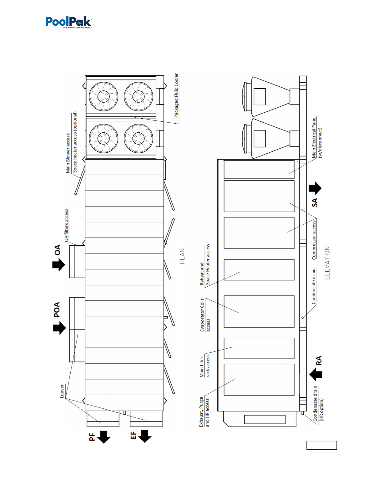
dehumidifierarrangementisshownonPic.C.1.
DehumidifierOptions
Indoororoutdoorinstallation.
o Note:Pic.C.1.showsoutdoormodel,equippedwithlouvers(toprotectairintakeanddischarge
openingsfromelements).Indoormodelwouldhaveductsconnectedtorespectiveopenings,no
louverswouldbeneeded.
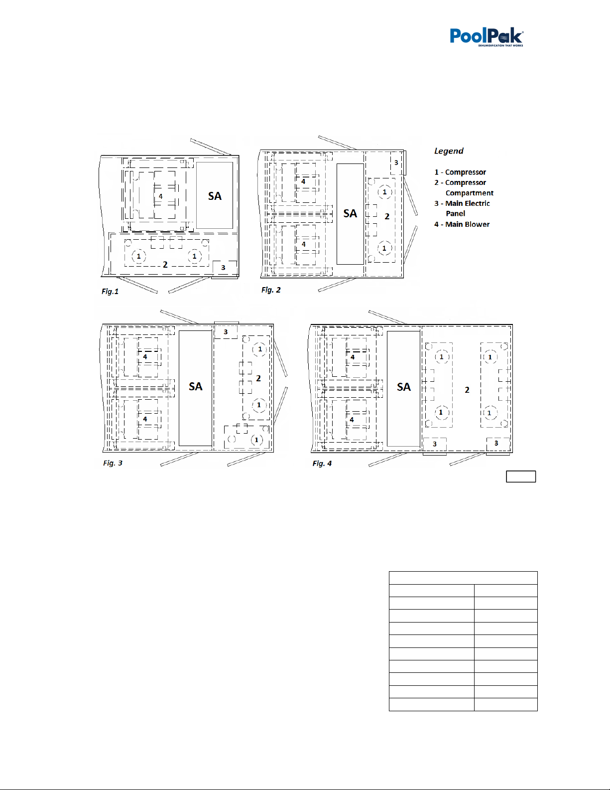
Capacity(numberofcompressors)–twotofourcompressors(seeDehumidifierOptionalArrangementbelow
formoredetails):
o Two‐compressordehumidifieroption(modelsPPK070toPPK340).
o Three‐compressordehumidifieroption(modelsPPK380andPPK420).
o Four‐compressordehumidifieroption(modelPPK530).
Airflow/ductworkconnection*.Pic.C.1showssomeoptionsonly;eachoptionlocationavailabilitydependson
thedehumidifierinstallation(indoororoutdoor)andotheroptions:
o ReturnAir(RA)ductworkconnection‐top,bottom,end,sides.
o SupplyAir(SA)ductworkconnection–top,bottom,sides.
o OptionalMinOutdoorAir(OA)ductworkconnection/termination–top,sides.
o OptionalMinExhaustFan(EF)andPurgeFan(PF)ductworkconnections/terminations–end,sides.
o OptionalPurgeOutdoorAir(POA)ductworkconnection/termination‐top,sides.
OptionalPoolWaterHeating**.
o Dehumidifiercanaccommodateuptotwopoolwaterheatingcircuits
OptionalSpaceHeating‐hotwatercoil,electricorgasheater***.
OptionalHeatRecovery(HR)circuit.
AirConditioning(AC)*–externalwatercoolingorfluidcooler(packagedorseparate).
o Note:Pic.C.1showsoutdoormodelwith“packaged”fluidcooler(mountedwiththedehumidifier).
“Packaged’ACoptionisavailableforoutdoormodelsonly;alternatively,indoorandoutdoormodels
couldbefittedforseparate/remoteACoption–remotefluidcoolerorotherexternalcoolingmedia
source.
*
Someavailableoptions(tonnage,ductworkconnections,ACoptionsetc.)areshown.Refertothesubmittal
andotherrelevantdocumentationforyourdehumidifier’soptions.
** Thepoolwaterheatingoptionreliesoncompressor‐createdexcessheatandisusedasanadditional
heatingsource.Itdoesnoteliminatetheneedforamainpoolwaterheater.
*** Forspecificdetailsonspaceheating(hotwater,gas,electric)option,refertothesubmittalandother
documentation:
Gas‐firedductheatercanbeinstalledinternally(fittedinsidethedehumidifieratthefactory)orprovidedforfield
installation(tobefittedinthesupplyairductwork).
Electricheaterorhotwatercoil,dependingoncapacity,model,size,etc.,canbeinstalledexternally(mountedonthe
topofSAopeningorfittedinthesupplyairductwork)orinternally.Refertoyourdehumidifier’ssubmittal
documentation.
Attention!EquipmentClearancesandDimensions!
CAUTION!
Forequipmentproperoperation,maintenanceandservice,respectiveclearancesshouldbe
maintained.Generally,30”clearancestotheequipmentmustbekeptforthemaintenanceandservicepurposes.
Forthespecificrequiredclearancesinformation,aswellasdehumidifieroveralldimensions,distancestopipe
connections,ductconnectionsetc.,refertothesubmittaldocumentation.

C–GeneralInformation
OMM.C.P.AA.00
C‐
5
June
2018
DehumidifierExternalSystemsConnection
Pic.C.1showsprovisionsforexternalsystemsconnections,includingductwork,electricpowerandcontrolwires
andvariouspipingconnections.
Exceptforthecondensate,allotherpipingsystemsareoptionalandmaynotbepresentineach
dehumidifier
CondensateDrainLine–bottom,side(throughthedehumidifierbase).
AirConditioning(AC)Connection.
o PackagedACoption(outdoordehumidifierwithoutdoorfluidcooler(OAFC)incorporatedwiththe
dehumidifier),doesnotrequirepipingconnectiontoexternalACsystemordevice.
Pic1.C.showspackagedoutdoormodelwithOAFCmountedattheendofthedehumidifier;
alternatively,ifrequested,OAFCcouldbemountedontheroofofthedehumidifier.
o Remote(“split”)ACoption(indoororoutdoordehumidifier,connectedtoexternalcooled
water/glycolsystemorremotefluidcooler)–sideorend(throughthecompressorcompartment
wall)connection.
PoolWaterHeating–bottom,side.
Spaceheating(HotWaterconnection)–bottom,side.
o Someconnectionlocationoptionsforboth,poolandspace,heatingpipelines,arelimitedtoindoor
installationonly–refertosubmittaldocumentation
SpaceHeating(GasHeaterconnection,gasline).Ifthedehumidifierisequippedwithagasheater(boiler,gas
furnaceetc.)forspaceheatingpurposes,thegaslineconnectionistobebroughttothegasheaterdirectly.
ElectricPowerandControlConnection.Electricpowerisnormallybroughttothedehumidifierdisconnect,
normallyincorporatedwithmainelectricpanel(seePic.C.1).Ifdehumidifierisnotequippedwiththe
disconnect,powerlinestobebroughtdirectlytothemainelectricpanel.
DehumidifierOptionalArrangement.
Multi‐CompressorArrangementandCompressorCompartmentLayout
Largemodeldehumidifiers,dependingonrequiredcapacity,couldhavetwo,threeorfourcompressors.Pic.C.2
showsoptionsofdehumidifiersupplyair(SA)endandcompressorcompartmentarrangement,basedonnumber
ofcompressors.
Pic.C.2showstopsupplyair(SA)connectionoptionasanexample–otherconnectionoptionsareavailablealso.
CAUTION!
Currentmanualshowsgeneral/defaultconnections’location.Fordetailsregardingspecific
dehumidifier’sconnections(actuallocation,pipingsizesandpositiondimensions,circuittypeandflowdirection
etc.),refertothedehumidifier’ssubmittaldocumentationaswellasdehumidifier’slabelsandstickers.
NOTE.
DehumidifierMUSTbeequippedwithaP‐trapatthecondensateconnectionforproperoperation!If
dehumidifierisrequestedfromthefactorywithoutP‐trap,oneMUSTbeinstalledonsitepriortodehumidifier
bein
g
commissioned.RefertotheInstallationManualfordetails.
WARNING!
GasLine.Thegaslinemustbeinstalledinaccordancewithrespectivedevicedocumentation
(boiler,furnace,etc.)andlocalcodesandregulations.

C–GeneralInformation
C‐
6
Fortwo‐compressordehumidifier,compressorcompartmentmayhaveside(Fig.1;sameasdehumidifier,shown
onPic.C.1)orend(Fig.2)location.Endlocationismostlyusedinhighercapacitydehumidifiers.
Three‐andfour‐compressordehumidifiers(Fig.3andFig.4,respectively)normallyhaveendlocationofthe
compressorcompartment.
AirConditioningOptions–OutdoorAirFluidCoolers(OAFC).
BasicviewsofstandardairconditioningoptionsareshownonPic.C.4(below);standardcombinationsofthe
dehumidifierandrespectivefluidcooler(basedontheircapacities)areshowninTableC.1.Note,thatdepending
onnumberoffactors,dehumidifiermayhavedifferentcoolerprovidedwithit‐refertothedehumidifier’s
submittaldocumentationformoredetails.
StandardfluidcoolersusedwiththismodelofdehumidifierisNG‐Vseries,
composedofnumberof“two‐coils‐two‐fans”blocks,basedonrequired
capacityofthecooler:
FluidcoolerNG‐V‐12(Pic.C.4,Fig.1)iscomposedofonesuchblock;
NG‐V‐22(Fig.2)composedoftwosuchblocksetc.largestsingle
fluidcooler,NG‐V‐62(Fig.3)composedofsixofthem.
Asanoption,eachblockoffluidcoolercouldbeequippedwiththepump
package(asshownonFig.1forNG‐V‐12).
TableC.1
Dehumidifier FluidCooler
PPK070–100 NG‐V‐12
PPK070–200 NG‐V‐22
PPK140–300 NG‐V‐32
PPK260–420 NG‐V‐42
PPK340–530 NG‐V‐52
PPK380–530 NG‐V‐62
PPK380–420 2*NG‐V‐32
PPK420–530 2*NG‐V‐42
PPK530 2*NG‐V‐52
Pic.C.2

C–GeneralInformation
OMM.C.P.AA.00
C‐
7
June
2018
Attention!EquipmentClearances!
Properclearancesshouldbemaintainedforadequateairflowandheatrejection!Generally,upto36”sideand
96”topclearancesarerequired.Formoreinformationonclearancesaswellasequipmentdimensionsandother
details
,
refertothesubmittaldocumentation.
Pic.C.4

C–GeneralInformation
C‐
8
EquipmentSpecificData
Specificinformationforindividualdehumidifiersisprovidedinthefollowingmethods:
MainLabel(Pic.C.5):themanufacturertag
attachedtothefrontofthedehumidifier
includesthedehumidifier’smostcritical
data:
Generaldataincluding:
o Serialnumber
o Dehumidifiermodel
(nomenclature)
o Designroomconditions(air
temperatureandhumidity)
Operationaldata,including:
o Refrigeration(refrigeranttype,
charge,etc.)
o Electrical/airflow
(dehumidifiervoltage,CFM,
etc.)
o Otherapplicabledata(pool
heating,space/auxiliary
heatingfeatures,etc.)
LabelsandStickers:attachedwhen
applicabletotheexteriorandinteriorofthe
dehumidifiertoshow:
Externalsystemsconnections
location/direction
(pool/spaceheating,coolingcircuits,
condensate)
Airfilterlocations,quantity,andsize.
AdditionalInfo(warning,cautionstickers,etc.)
WiringDiagrams:attachedtotheinteriorsideofthe
dehumidifier,depictdehumidifiercontrolandpower
wiring.
Remotelyinstalledcondenserorcoolerwouldhaveitsspecificinformationprovidedinsimilarmanner(labelsetc.).
Attention!GlycolCircuits.
Unlessotherwiseindicated,equipmentfluidcircuits(exceptforrefrigerationandpoolwatercircuits)suchasheat
recoveryloop,compressorglycolloop,boilerpackage,fluidcooleretc.,arenormallyfilled/tobefilledwith
water/glycolmixture;normally,rustinhibitor‐infusedfood‐gradepropyleneglycolisused.
GlycolmixtureconcentrationisnormallyshownonMainLabel–referasneeded.
Note:
Themainlabelshownaboveisjustanexample.
Pic.C.5

D–LayoutandComponents
OMM.D.P.AA.00
D‐
1
June
2018
LayoutandComponents
Thegenerallayoutandcomponentslocationisthesameforalldehumidifiersofcurrenttype,howeversomemay
vary,basedonthedehumidifier’sspecificoptions–refertosubmittaldocumentation.Pic.D.1belowshows
all/mostavailableoptions,someofwhichmaynotbepresentonyourdehumidifier.
DehumidifierMainComponents
MainBlower(1)isinthemainblowercompartmentbehindornexttotheCompressorCompartment(3)with
MainElectricPanel(2).Basedonairflowrequirements,numberofmainblowersmayvary(uptofour).
o Twoblowerscouldbeinstalledeithersidebysideorstackedonatopofeachother(Pic.D.1A);four
blowers’arrangementwouldhavetwostacks,shownonPic.1.DA,installedsidebyside.
MinOutdoorAir(OA)Opening(4)hasamotorizeddamperandfilter(s).TheManualOADamper(5)isusually
usedtosetproperamountofoutdoorairintake;insomecases,itcouldbeequippedwithmodulating
actuatorforautomaticadjustmentofoutdoorairintake.
o Outdoor‐installeddehumidifierwouldhavelouver(s)(76)installedattheOAopening.
MinExhaustFan(s)(EF)Assembly(6)(fanandmotorizeddamper)islocatedonthedehumidifier’sreturnair
side;ExhaustAiropeninginoutdoor‐installeddehumidifierisequippedwithlouver(s)(76)also.
o MinExhaustFanAssemblyishingedandcouldbeopenedforbetteraccesstothefanelectricbox.
Dehumidifier,equippedwithHeatRecovery(HR)option,wouldhaveHRglycolcoils(71),installedattheMin
Exhaust(EF)andMinOutdoorAir(OA)openings,andHRpump(72),installedinreturnaircompartment.
o IfHRoptionispresent,MinExhaustFanAssemblywouldnormallybeequippedwithafilterrack.
IfdehumidifierisequippedwithPurgeoption,additionalPurge‐exhaustfan(s)(PF)(73)withmotorized
damperwouldbeinstalledondehumidifier’sreturnairside,aswellasadditional(“Purge”)OutdoorAir(POA)
(74)opening(s),equippedwithmotorizeddampers,wouldbelocateddirectlyupstreamofMainFilterRack
(9).MotorizedReturnAir(RA)damper(75)wouldbelocatedbetweenreturnairsideandPOAopening(s).
o Outdoor‐installeddehumidifierwouldhavelouvers(76)installedatthePurge‐exhaustfanandPurge
OutdoorAiropenings.
RefrigerationEvaporatorcoils(7)andwater/glycolReheatcoils(8)arelocateddirectlydownstreamofthe
MainFilterRack(9).
o MotorizedEvaporatorBypassDamper(10)is
locatednexttotheevaporatorcoils;itby‐passes
portionofairaroundevaporator,thusadjusting
compressorcircuitoperation.Somedehumidifiers,
basedonairflowrequirement,couldbeequipped
withadditionalmanualby‐passdamperalso.
o Eachcompressorcircuithasitsownevaporator
coil(s)set(oneortwocoilspercircuit,dependingon
capacity),whileallreheatcoils,generally,are
manifoldedtogetherandservebothcompressor
circuitstogether.
Spaceheaterlocation,ifthedehumidifierisequippedwith
one,dependsontheheatertype:
o HotwatercoilorElectricheater(11a)isusually
locateddirectlydownstreamofthereheatcoil;
o Gasheater(11b)isusuallylocateddownstreamof
themainblower(s).
Pic.D.1A

D–LayoutandComponents
D‐
2
11b 2
1
3
5
4
7
8
9
11a
10
Pic.D.1B
72
75
71
74
6
71
73
76
76
21
22
23
24
29

D–LayoutandComponents
OMM.D.P.AA.00
D‐
3
June
2018
CompressorCompartmentandMainElectricPanel(detailed;seePic.D.1C).
Compressor(s)(13),Receiver(s)(14)andothercomponentsarelocatedwithintheCompressorCompartment
(3):
o Eachcompressorcircuithasglycol‐to‐refrigerantplateheatexchanger(16)and,commontoboth
circuits,glycolpump(16a),thatcirculateswater/glycoltorejectcompressor‐generatedheat.
o Motorizedwater/glycolReheat(79)andAC(80)valves’openingpositiondetermineshowmuchfluid
isdivertedtorespectivecoil(s)(reheatandfluidcoolerorexternalheatsink).
o Ifthedehumidifierhasthestandardpoolwaterheatingoption,thecompressorcircuitadditionally
includesthecoaxialpoolwaterheatexchangers(15)andrefrigerationpoolwaterheatingsolenoid
valves.Numberofpoolwaterheatexchangervariesbasedondehumidifiertypeandcapacity.
o Controlsub‐panelwithMainControl
Board(17)andOperatorPanel(18)is
normallymountedonthecompressor
standframe.
MainElectricPanel(2)containsmain
blower(s)VFD(variablefrequencydrive)
(78),mainDisconnect(77),ifoneis
installed,andotherelectricalandcontrol
components(contactors,fuses,control
transformeretc.).
PackagedOutdoorFluidCooler(19),if
dehumidifierisequippedwithit,is
normallymountedattheendofthe
dehumidifier,adjacenttocompressor
compartment/supplyairend(seePic.
D.1D).
13
14
15
18
17
19
77
Pic.D.1C
Pic.D.1D
78
16
16a
13
27
28
25,26
80
79

D–LayoutandComponents
D‐
4
ControlSystem
Thedehumidifiercontrolsystemiscomposedofsensors,spreadthroughoutthedehumidifier,MainControl
Board,OperatorPanelandotherelectriccomponents,locatedintheMainElectricPanel.
TemperatureSensors(Pic.D.2):
a) Temperaturesensors(thermistors)areusedtomonitor
varioustemperatures(air,water,compressor,etc.);
b) Combosensorisusedtomonitorairtemperatureand
humidity.
Compressoroperationismonitoredwithpressuresensors(Pic.D.3):
c) PressureTransducers(asmainoperationalcontrolandsafety)and
d) PressureSwitches(fast‐reactingbackupsafety).
Note.SensorsandsafetiesapproximatelocationisshownonPic.D.1Band
D.1C–referasneeded.
RAComboSensor(21)measurestemperatureandhumidityofthepoolroomair(ReturnAir)enteringthe
dehumidifier.Itislocatedatthereturnairductworkconnectiontothedehumidifier.
OATemperatureSensor(22)measuresoutdoorairtemperature;it’slocatedattheOAfilterrack.
o Asanoption,thecombosensor(insteadofregularthermistor)canbeinstalledattheOAintaketo
measureboththetemperatureandhumidityoftheoutdoorair.
ET(EvapT)TemperatureSensor(23)measuresthetemperatureofairleavingevaporatorcoil.It’slocated
directlydownstreamoftheevaporatorcoil(s)(onesensorpereachcompressorcircuit).
SAtemperaturesensor(24)measuresthetemperatureoftheairleavingthedehumidifier(suppliedtothe
premise).Itmustbelocateddownstreamofthespaceheater:
o SAtemperaturesensorofdehumidifier,equippedwithgasheater,wouldbecomposedoffour
regulartemperaturesensors,installedindifferentpointsatsupplyductconnection,averaging
temperaturereading.
Ifthedehumidifierisequippedwiththepoolheatingoption,thePoolWaterTemperaturesensors(PoolIn
(25)andPoolOut(26))measuretheenteringandleavingpoolwatertemperature.Thesensorsarelocatedat
respectivemanifolds.
o Asanoption,thepoolwaterheatexchangerpiping/manifoldmayhavewaterflowswitchalso.
Thecompressor’sdischargeline(highpressureside)isequippedwithTemperatureandPressuresensorsset‐
DischargeTemperatureSensor,HighPressureTransducerandHighPressureSwitch(27)‐toprotectthe
compressorandcontrolitsoperation.AsimilarfunctionisperformedbySuctionTemperatureSensor,Low
PressureTransducerandLowPressureSwitch(28)locatedatcompressor’ssuctionline(lowpressureside).
o Saidsafeties/sensorsareinstalledoneachcompressor.
IfdehumidifierisequippedwithHeatRecoveryoption,itcouldalsohaveExhaustAir(EA)Temperature
Sensor(29),installeddownstreamofexhaust‐sidelocatedheatrecoveryglycolcoil.
MainElectricPanel,apartfromdeviceslistedabove(controlboard,OP,etc.)alsocontainsVoltageMonitor;some
optionalcontrolsensorsanddevicessuchasanairpressuredifferentialsensor,currentsensor(s).Itmayalsobe
locatedinmainelectricalpanelorinthedehumidifieringeneral.
b
a
c
d
Pic.D.3
Pic.D.2

D–LayoutandComponents
OMM.D.P.AA.00
D‐
5
June
2018
OutdoorAirFluidCoolersLayoutandComponents
.
ThegenerallayoutofACoptions(air‐andwater‐cooled)isshownonPic.D.5belowwiththeoutdoorfluidcooler
NG‐V‐12,equippedwithadditionalpumppackage(Fig.1)andNG‐V‐32(Fig.2)asanexample.Whilelayoutand
maincomponentsaresimilarforallapplicableACoptions,therearesomedeviations(numberoffans,
composition,etc.).RefertoACOptionsBasicView(BasicInformationchapter)foradditionalinformation.
Cooling(AC)coils(31)(whereheatfromglycolmixtureisrejectedtotheambientair)ismountedontometal
frame,upstream(before)thefans(32),thatpullstheairthroughthecoilstoabsorbtheheat.
o Normally,fluidcoolerwouldhavemultiplecoilsandfans.CoolerNG‐V‐12(Fig.1),comprisedoftwo
coils,mountedontheangletoeachother,andtwofans,presentsasingleblock.Dependingonthe
capacity,coolercouldbecomprisedofuptosixsuchsingleblocks,stackedsidebysideonthesame
frameandmanifoldedtogether–NG‐V‐32iscomprisedofthreesuchblocks.
Coolerpipingconnections(33)areidentifiedrespectively(IN–OUT);
o Insomecases,fluidcoolerpipingconnection(s)maybelocatedwithinpumppackagebox(37),iffluid
coolerisprovidedwithone.
o Pipingconnectionlocationmayvary–refertoparticularcoolerlabels,stickers,submittalandother
documentation.
Electricpowerisnormallytobebroughttodisconnect(35)(ifcoolerisequippedwithsuch),whichfeedsitto
theelectricalbox(36),thatcontainscoolerpowerandcontrolapparatuses.
o Dependingonfluidcoolerspecifics,locationofelectricalboxmayslightlydiffer;insomecases,
electricalboxmaybeincorporatedintopumppackageorlocatedontheoppositesideofthefluid
cooler.
32
36
35
33
37 31
Pic.D.5
33
31

D–LayoutandComponents
D‐
6
FluidCoolersPumpPackage.
FluidCoolers,ifequippedwithsuchoption,wouldhaveapumppackagebox.Pic.D.6belowshowsgenerallayout
ofpumppackages,usedforNG‐Vmodelfluidcoolers.Note,thatthepackagecouldbemountedontothefluid
coolerdirectly(standard)orprovidedseparately.
Pump(38)establishesglycolmixturecirculationthrough
thefluidcooleranddehumidifier;
Expansiontank(39)compensatesfortemperature‐
basedglycolvolumefluctuation;
Thepumppackageelectricalsub‐panel(40)containsthe
pumppackageelectricalpowerandcontrolapparatuses.
Thepumppackagemanifoldsareusuallyequippedwith
pressuregauges,automaticairventingvalve,draining
andothervalves.
Pic.D.6
38
40
39

E–SequenceofOperation
OMM.E.P.AA.00
E‐
1
June
2018
SequenceofOperation
Thedehumidifier’sventilationsystemestablishestherequiredairflowthroughthedehumidifier.Thecontrol
systemcomparesairtemperatureandhumiditytotheirdesiredvalues(setpoints)andproceedstodehumidify,
coolorheattherecirculatingair.
Ifthedehumidifierisequippedwiththepoolwaterheatingoption,thepoolwatertemperatureiscomparedtoits
setpointandpoolheatingisprovidedifrequired.
SetPoints
Thecontrolsystemisconstantlyadjustingunitoperationtoachieveandmaintainsaidparameterswithincouple
degrees/percentofthesetpoint.
Refertothedehumidifier’smainlabelforthedesignvalueofcontrolparameters,aswellasthefollowingnote.
Ventilation.
Themainblowerrunscontinuously,establishingrequired.Themainblowerspeedispre‐setviaadjustablevariable
signal.
MinimumExhaustFan(EF),ifdehumidifierisequippedwithsuchoption,directsportionofreturnairoutdoors.
Likemainblower,exhaustfan(s)speedisalsocontrolledviaadjustable(pre‐set)variablesignal,thatvariesbased
onscheduledventilationmode(Occupied,Non‐OccupiedandSpectator)orcallforEconomiserMode(aspartof
AirConditioningand/orDehumidificationoperation).
MinimumOutdoorAir(OA)damper,ifdehumidifierisequippedwithsuchoption,openstointroducefresh
outdoorairintothepremise.OAdampercouldbeequippedwithON/OFF(simplefullyopen–fullyclosed)or
modulating‐controlledactuator;latteronewouldbecontrolledsamewayasminimumexhaustfan.
Purge(AdditionalExhaust)Option.
AlongwithMinExhaustFanandMinOutdoorAirdamper,dehumidifiercouldhaveadditionalsetofexhaust
(purge)fan(s)(PF)andpurgeoutdoorairdamper(POA),commonlyreferredasPurge.Purgefan(s)andOA
damper(s)functionistoallowforhigherexhaustandfreshairamount,uptocomplete(100%)airchangeover
(whenallexhaustfansandOAdampersareattheirmaxcapacities).
PurgeFan(s)andPurgeOutdoorAirdamper(s)arecontrolledinthesamefashionasminexhaustfansandmin
outdoorair.SomedehumidifiersmaybeequippedwithadditionalReturnAirdamper:itclosesineventof
completeairchangeover,separatingreturnairsideofdehumidifierfromsupplyside(refertoLayoutand
Componentschapter,asneeded,forrespectivedevices’location).
Completeairchangeover,triggeredmanually,isknownasPurgeMode.
Note.ExternallyinstalledExhaustFan(s)andOutdoorAirdamper(s)couldbealsocontrolledbythe
dehumidifiercontrolsystem.Thisappliestoboth,MinimumandPurge/Additional,fansanddampers.
Note:
Toensurethedehumidifier’smosteconomicaloperation,werecommendmaintainingthefollowing
relationshipbetweenpoolwaterandroomairtemperatures:
RoomAirT=PoolWaterT+2˚F

E–SequenceofOperation
E‐
2
HeatRecoveryOption.
Dehumidifiers,packagedwithMinimumExhaustFanandMinimumOutdoorAirdamper,couldalsohave
additionalHeatRecovery(HR)closed‐loopglycolsystem.
HeatRecoveryloop(seePic.E.1below)consistsoftwocoils(air‐to‐glycolheatexchangers)andapump,
establishingglycolcirculationbetweenthem.Onecoil,installedatexhaustairopening,recoversportionof
exhaustedairenergy,anothercoil,installedatoutdoorairintake,transfersthiscapturedenergytoentering
outdoorair.
SpaceHeating
Whenpremiseairtemperaturedropsbelowthesetpoint,thedehumidifiercontrolsystemissuesacallforSpace
HeatingModeandengagesspaceheater(electricheater,hotwatercoilwithvalve,gasboileretc.)bysendingspace
heatingsignal,respectivetospaceheatercontroltype‐on/off,variable(0‐10VDC),etc.
AirConditioning,DehumidificationandPoolHeating.
Whenpremiseairtemperaturegoesover(exceeds)itssetpoint,thedehumidifiercontrolsystemissuesacallfor
AirConditioningMode.Respectively,whenpremiseairhumiditygoesover(exceeds)itssetpoint,thedehumidifier
controlsystemissuesacallforDehumidificationMode.Insomeinstances,thesecallsmayco‐exist.
ToexecuteDehumidificationorAirConditioning(Cooling)mode,controlsystem,dependingoncurrentconditions,
wouldresorttoavailablemeansofcoolingordehumidification.
EconomiserModeOption.
Note.EconomiserModerequiresdehumidifiertobeequippedwithfull(minandadditional)exhaustand
outdoorairoptions!
Ifoutdoorairisdryand/orcool,itcouldbeusedtodehumidifyand/orcoolthepremise.Inthiscase,oncallfor
DehumidificationorAirConditioningmode(s),controlsystemwouldsimplyincreaseexhaustfan(s)speedsignalto
directmorestalereturnairoutsideandbringinmoreoutdoor(dry/cool)airin,thusreducingsupplyairhumidity
and/ortemperature(asneeded).
Pic.E.1

E–SequenceofOperation
OMM.E.P.AA.00
E‐
3
June
2018
Compressor(s)
Wheneverthecompressoroperates,theevaporatorisalwaysdehumidifyingandcoolingthereturnair.Theheat
removedfromtheairattheevaporator,aswellastheheatfromthecompressor'saction,mustberejectedtoone
ofthreeheatsinks:room(premise)air,poolwater(ifapplicable)oroutdoors.Thecontrolsystemwilldirectthe
heattowhereitisneededbasedonroom(airandpoolwatertemperature)conditions:
Ifroomairisneededtobewarmedup–moreheatisdivertedtowardsreheatcoil;
Ifpoolwaterisneededtobewarmedup–moreheatisdivertedtowardspoolheatingcoaxialheatexchanger
(ifdehumidifierisequippedwiththisoption).
Restoftheheat(ifany)isdivertedtowardsoutdoors(outdoorfluidcooler,externalheatsinksetc.)
CompressorCircuitOperation
PipingschematicforcompressorcircuitisshownonPic.E.2.
Schematicshowssinglecompressorcircuit(secondcompressorcircuitschematicisthesame)andcommonto
bothcompressorcircuits’glycolcoolingcircuit.
Circuitoperationbelowappliestobothcompressors;compressorsarestaged–iffirstcompressor’scapacityis
notenoughtosatisfythecall,secondcompressorwillbeengagedaftercertaintimedelay.
Whenademandrequiresthecompressortooperate,thefollowingsequenceoccurs:
Oncebloweroperation,relatedsafetiesandtimersareconfirmedbythecontrolsystem,followingoccurs:
o Compressorglycolpumpstarts,establishingcoolingglycol/waterflowthroughthecompressorfluid
circuit‐plateheatexchanger(s)andfluidcoolingcoils(reheatand/orfluidcoolerorexternalcooling
source).
o Pumpdownsolenoidvalveopensandoncepressurestabilizes,thecompressorstarts.
Basedonthepremiseairtemperature,theReheatandACvalveswouldadjusttheiropeningposition(open
more/closemore),reducingorincreasingfluidflowtoandthroughtherespectivefluidcoils:
ReheatandACvalvesarecontrolledinthesamemannerwithoppositeeffect:forexample,
whenACvalveopens10%more,Reheatvalvecloses10%moreetc.
o ifmoreheatisrequiredbytheroomair,theReheatvalveopensmore,andACvalveclosesmore,thus
divertingmorefluidtothereheatcoils(heatisrejectedtothepremise);
o ifmorecoolingisrequiredbytheroomair,theACvalveopensmore,andReheatvalveclosesmore,
thusdivertingmorefluidtothefluidcooler(heatisrejectedoutdoors).
o
Outdoorfluidcoolerfansareengagedonlyifatleastsomefluidisdivertedtowardsoutdoorfluidcooler
andcompressorpressureishigherthanpre‐setlevel(seeOutdoorFluidCoolerOperationbelow).
Dehumidifiers, equipped with pool water heating option, also engagetherefrigerationpoolwaterheating
solenoidvalvetorejectheatintothepoolwater,basedonpoolwatertemperature.
Oncedemandforthecompressor’soperationisremoved(respectivecallissatisfied),thepumpdownsolenoid
valve closes; once the compressor suction pressure reaches the pre‐set pressure, the glycol pump and
compressorstop.
OutdoorFluidCoolerOperation.
Basedonthetypeoftheoutdoorcondenserorfluidcoolerfans’type(two‐speedfansorEC‐type/modulating
fans),respectivesignal(s)aresentbycontrolsystemtoengagesaidfan(s):fortwo‐speedfans‐on/offsignals
(switchingspeeds,basedoncompressorheadpressurelevel),forEC‐typefans‐variable0‐10VDCsignal
(proportionaltothecompressorheadpressurelevel).Refertothefans’typeandwiringdiagramif/whenneeded.
Ifthefluidcoolerisequippedwiththebuilt‐inpumppackage(toestablishcoolingfluidflowbetweendehumidifier
andthefluidcoolerortoserveasadditional/boosterpump),thesaidpumpisalsoengagedalongwithfluidcooler
fans–pumpwouldstayengagedwhilefansareengaged(regardlessofthefans’speed).
This manual suits for next models
8
Table of contents
Other PoolPak Dehumidifier manuals