PoolPak PCP Series User manual

© 2018 PoolPak LLC. All rights reserved.
Operation and
Maintenance Manual
PCP Series Dehumidifiers
PCP 3000 to PCP 6000
PCP 3030 to PCP 5050
Indoor/Outdoor Model
FORM #: SVW11-PCPOMMBX-20180828
UPDATED: AUGUST 2018

TABLE OF CONTENTS
General Information ................................................................................................................... 4
Operating Safety (Warnings, Cautions, and Notes) ........................................................................................4
Reference and Additional Information............................................................................................................5
Contact Us .................................................................................................................................................5
Basic Information .......................................................................................................................................6
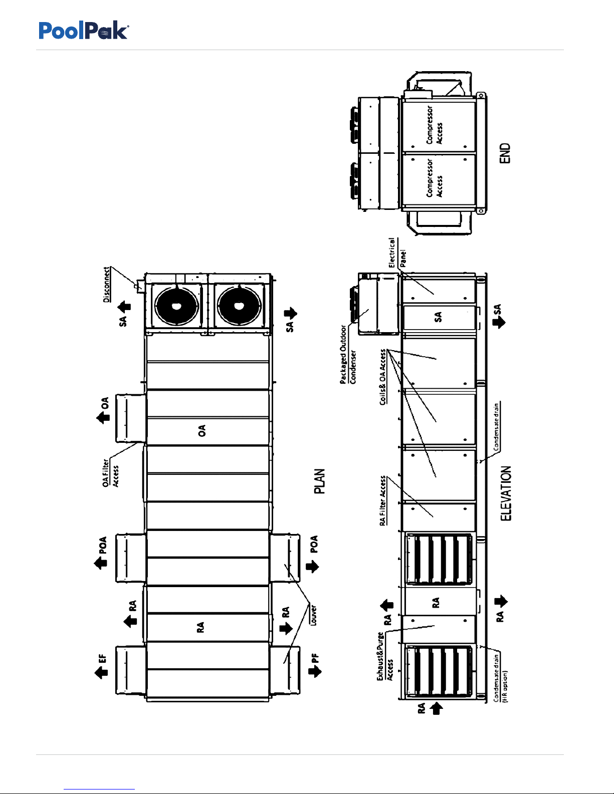
Dehumidifier View and Options ....................................................................................................................6
Dehumidifier Options ..................................................................................................................................7
Dehumidifier External Systems Connection .....................................................................................................8
Dehumidifier Optional Arrangement. .............................................................................................................9
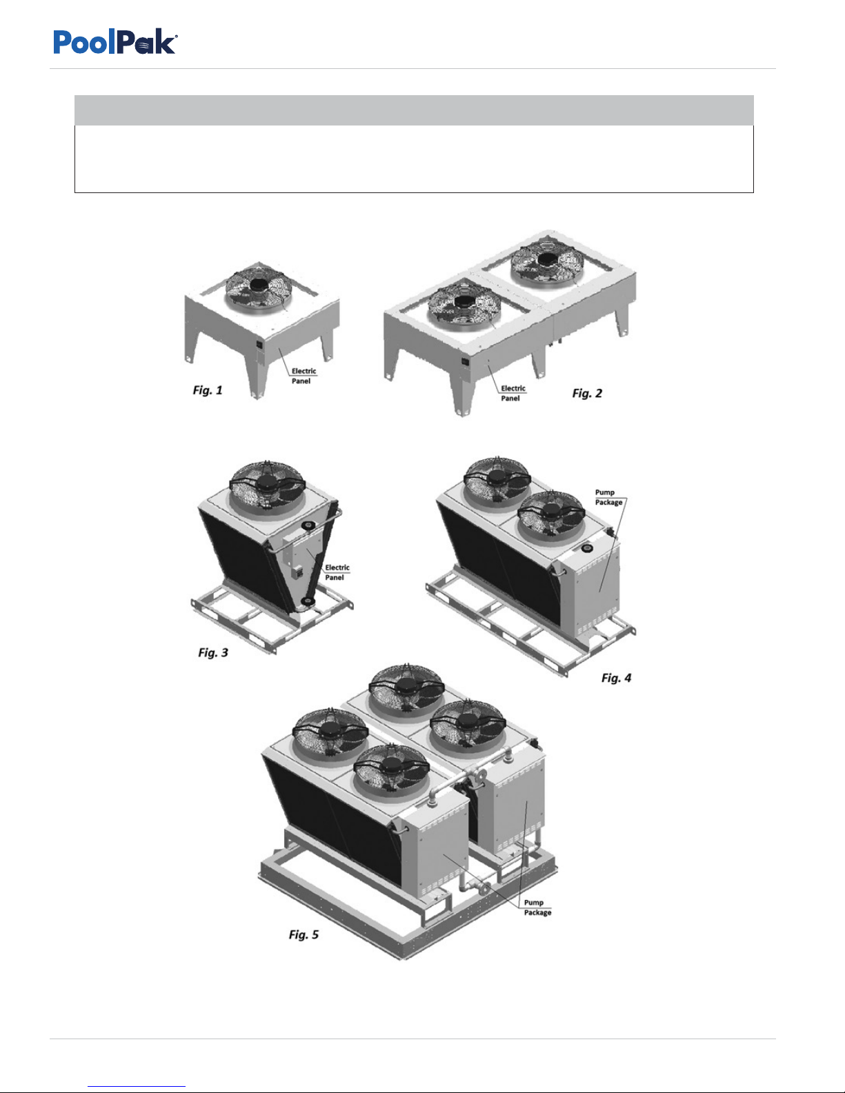
Air Conditioning Options – Outdoor Air Condensers (OACC) and Fluid Coolers (OAFC).....................................9
Equipment Specific Data ........................................................................................................................... 11
Layout and Components ........................................................................................................... 13
Dehumidifier Main Components ................................................................................................................. 13
Control System..........................................................................................................................................15
Outdoor Air Condensers and Fluid Coolers Layout and Components............................................................... 17
Fluid Coolers Pump Package....................................................................................................................... 18
Sequence of Operation ............................................................................................................. 19
Set Points .................................................................................................................................................19
Ventilation. ...............................................................................................................................................19
Purge (Additional Exhaust) Option...............................................................................................................19
Heat Recovery Option. ..............................................................................................................................20
Air Conditioning, Dehumidification and Pool Heating. ...................................................................................20
Economiser Mode Option. ........................................................................................................................20
Compressor(s)...........................................................................................................................................21
Compressor Circuit Operation ....................................................................................................................21
Outdoor Air Condenser and Fluid Cooler Operation.....................................................................................22
Space Heating..........................................................................................................................................22
Interface and Communication ................................................................................................... 23
Touch Display Operator Panel ...................................................................................................................23
Alarms.....................................................................................................................................................24
Remote Communication (Virtual-Tech and BMS) ............................................................................................25
Virtual-Tech...............................................................................................................................................25
BMS (Building Management System) ...........................................................................................................26
Basic Maintenance .................................................................................................................... 27
Maintenance and Safety............................................................................................................................27
Maintenance Key Points .............................................................................................................................27
Routine Maintenance Program ....................................................................................................................28
Specific Components Maintenance .............................................................................................................29
ASHRAE
62.1-2 013
3491 Industrial Drive
York, Pennsylvania 17402 USA
717-757-2648 • Fax 717-757-5085 • www.PoolPak.com
© 2018 PoolPak LLC. All rights reserved. SVW11-PCPOMMBX-20180828

© 2018 PoolPak LLC. All rights reserved. PCP Series BX - Operation and Maintenance Manual | 3
Table of Contents
Warranty.................................................................................................................................. 30
General Policy ..........................................................................................................................................30
Warranty Void Unless Registered ................................................................................................................30
Initial 90-day Warranty .............................................................................................................................30
Virtual-Tech Conditional One Year Extended Labour Warranty .......................................................................30
Two Year Parts Warranty ...........................................................................................................................30
Replacement Part Warranty........................................................................................................................30
Applicability.............................................................................................................................................30
Limitations ................................................................................................................................................ 31
Force Majeure .......................................................................................................................................... 31
Optional 5 Compressor Warranty............................................................................................................... 31
Optional 5 Airside Coil Warranty ............................................................................................................... 31
Optional 10 Year Airside Coil Warranty......................................................................................................32
Optional 5 Year Driveline Warranty ............................................................................................................32
FIGURES
Figure 1. Standard PCP1400 to PCP5000 ......................................................................................................6
Figure 2. StakPak Model ..............................................................................................................................9
Figure 3. PCP3030 Double-Condenser ........................................................................................................10
Figure 4. Main Label ................................................................................................................................. 12
Figure 5. BX Drawing................................................................................................................................. 14
Figure 6. Temperature Sensors ....................................................................................................................15
Figure 7. Pressure Sensors...........................................................................................................................15
Figure 8. Sensors and Safeties.................................................................................................................... 16
Figure 9. AC Options.................................................................................................................................17
Figure 10. Pump Package........................................................................................................................... 18
Figure 11. Heat Recovery Loop ...................................................................................................................20
Figure 12. Piping Schematic ....................................................................................................................... 21
Figure 13. Boiler Package Piping Schematic .................................................................................................22
Figure 14. Touch Display Operator Panel ....................................................................................................23
Figure 15. Main Electric Panel.....................................................................................................................25
TABLES
Table 1. Dehumidifier-AC Combination*.........................................................................................................9
Table 2. Most Common Alarms/Alerts .........................................................................................................24
Table 3. Recommended Maintenance Tasks and Intervals...............................................................................28

Beware of moving parts and hot surfaces!
• Make sure to stop all moving parts (fans, blowers, etc.) before accessing the equipment’s internal space
• Be aware of hot surfaces (hot refrigeration, space heating pipes, coils, heaters, etc.)
Beware of electrical power and high electrical voltage!
• Follow proper safety procedures – lockout, tagout, and other respective procedures
• Failure to follow safety procedures can result in serious injury or death
Beware of high pressures and chemicals!
• Dehumidifiers, equipped with compressors, contain refrigerant under high pressure; oil is also contained in
the compressor and refrigeration circuit(s)
• Some dehumidifiers may also contain other liquids such as glycol mixtures and pool water
Only qualified technicians should install, operate, maintain or service mechanical equipment including
PoolPak’s dehumidification system. Make sure to read this manual before performing any installation tasks to
familiarize yourself with the equipment as well as with any potential hazards. Always exercise caution!
General Information
4| PCP Series BX - Operation and Maintenance Manual www.poolpak.com | 717-757-2648
GENERAL INFORMATION
This manual provides basic information about the applicable PoolPak®LLC dehumidifier and its operation.
Important information regarding installation, maintenance, and start up as well as additional and auxiliary systems
and devices (outdoor condenser, communication interfaces, etc.) is normally provided with the dehumidifier and can
also be obtained at PoolPak®LLC (see Contact Us on next page).
Operating Safety (Warnings, Cautions, and Notes)
FOR YOUR SAFETY: READ BEFORE PERFORMING ANY INSTALLATION OR OTHER TASKS!
WARNING! Indicates a potentially hazardous situation which could result in serious injury or death if handled improperly.
CAUTION! Indicates a potentially hazardous situation which could result in moderate injury
or equipment damage if handled improperly.
Indicates a situation that could result in equipment damage or improper/ineffective operation if handled improperly.
!WARNING
!CAUTION
NOTE
The following warnings, cautions, and notes appear throughout this manual and referenced documentation
whenever special care must be taken to avoid potential hazards that could result in equipment malfunction
or damage, personal injury, or death.

General Information
© 2018 PoolPak LLC. All rights reserved. PCP Series BX - Operation and Maintenance Manual | 5
Attention: Installation and Service Contractors
Any work (installation, start up, service, maintenance, repair, etc.) on any mechanical equipment
(dehumidifier, outdoor condenser, fluid cooler, etc.) must be performed in accordance with respective PoolPak
recommendations as well as submittal documentation, local Codes and Regulations, and appropriate field practices.
Failure to do so could result in personal injury, equipment damage or malfunction, and will void equipment warranty.
Only qualified and properly trained individuals should perform tasks on this equipment.
Attention: Maintenance Team
To ensure equipment longevity and proper and efficient operation, the dehumidifier and its auxiliary systems
and devices (outdoor condenser, fluid cooler, boiler package, etc.) should be maintained properly and regularly.
Failure to do so could negatively affect premise comfort levels and people’s health. It could also lead to equipment
damage, malfunction, premature tear and ware and may void equipment warranty.
!WARNING
!CAUTION
Reference and Additional Information
For safe, efficient and problem-free operation, it is critical to handle the dehumidifier (as well as related systems and
components) properly at each step - from receiving and storage to installation and start up. Relevant information can
be found in the respective documents (like Installation Manual) provided with the dehumidifier.
This manual and other related documents could be obtained from PoolPak®LLC (see Contact Us below).
Contact Us
PoolPak®LLC | 3491 Industrial Drive | York, PA 17402 USA
717. 7 5 7. 26 4 8 | F a x : 717. 75 7. 5 0 8 5
www.poolpak.com | sales@poolpak.com | service@poolpak.com | parts@poolpak.com

Figure 1. Example PCP5000 with purge and piggy-backed condenser
General Information
6| PCP Series BX - Operation and Maintenance Manual www.poolpak.com | 717-757-2648
Basic Information
Dehumidifier View and Options
PoolPak standard PCP3000 to PCP6000
dehumidifier general views,as well as some options,
are shown on the next page. Figure 1 shows only
one example of dehumidifier arrangement, refer to
submittal documentation for specific details.

General Information
© 2018 PoolPak LLC. All rights reserved. PCP Series BX - Operation and Maintenance Manual | 7
Dehumidifier Options
• Indoor or outdoor installation.
Figure 1 shows outdoor model, equipped with louvers (to protect air intake and discharge openings
from elements). Indoor model would have ducts connected to respective openings, no louvers would
be needed.
• Single-compressor dehumidifiers, 8 to 16 tons’ capacity (apprx.) – model PCP3000*.
• Two-compressor dehumidifier option (see Dehumidifier Optional Arrangement for details):
16 to 32 tons’ capacity (appx.) – models PCP3030 to PCP5050;
16 and 20 tons’ capacity (apprx.) – models PCP5500 and PCP6000.
• Lower compressor capacity 4 to 7 tons is normally provided in different cabinet arrangement; however, to
accommodate additional ventilation and other options, the smaller compressor capacity could be provided
in the larger BX cabinet.
• Airflow/ductwork connection options* – as shown in figure and described below (some option locations
availability depends on the dehumidifier installation – indoor or outdoor):
Return Air (RA) ductwork connection – top, bottom, end, sides
Supply Air (SA)ductwork connection – top, bottom, sides
Optional Min Outdoor Air (OA) ductwork connection/termination – top, sides
Optional Min Exhaust Fan (EF) and Purge Fan (PF) ductwork connections/terminations – end, sides
Optional Purge Outdoor Air (POA) ductwork connection/termination - top, sides
• Optional Pool Water Heating**
• Optional Space Heating – hot water coil, electric or gas heater***
• Optional Heat Recovery (HR) circuit
• Air Conditioning (AC)* – external water cooling, outdoor condenser or fluid cooler
* All available options (tonnage, ductwork connections, AC options etc.) are shown. Refer to the submittal and other relevant documentation for your
dehumidifier’s options.
** The pool water heating option relies on compressor-created excess heat and is used as an additional heating source. It does not eliminate the need
for a main pool water heater.
*** For specific details on space heating (hot water, gas, electric) option, refer to the submittal and other documentation:
• Gas-fired duct heater can be installed internally (fitted inside the dehumidifier at the factory) or provided for field installation (to be fitted in the
supply air ductwork).
• Electric heater or hot water coil, depending on capacity, model, size, etc., can be installed externally (mounted on the top of SA opening or
fitted in the supply air ductwork) or internally. Refer to your dehumidifier’s submittal documentation.
Attention! Equipment Clearances and Dimensions!
For equipment proper operation, maintenance and service, respective clearances should be maintained.
Generally, 30” clearances to the equipment must be kept for the maintenance and service purposes.
For the specific required clearances information, as well as dehumidifier overall dimensions,
distances to pipe connections, duct connections etc., refer to the submittal documentation.
!CAUTION

General Information
8| PCP Series BX - Operation and Maintenance Manual www.poolpak.com | 717-757-2648
Dehumidifier External Systems Connection
Figure 1 shows provisions for external systems connections, including ductwork, electric power and control wires
and various piping connections.
Dehumidifier MUST be equipped with a P-trap at the condensate connection for proper operation.
If dehumidifier is requested from the factory without P-trap, one MUST be installed on site prior
to dehumidifier being commissioned. Refer to the Installation Manual for details.
NOTE
Current manual shows general/default connections’ location. For details regarding specific dehumidifier’s connections
(actual location, piping sizes and position dimensions, circuit type and flow direction etc.), refer to the dehumidifier’s
submittal documentation as well as dehumidifier’s labels and stickers.
!CAUTION
Except for the condensate, all other piping systems are optional and may not be present in each dehumidifier
• Condensate Drain Line – bottom, side (through the dehumidifier base).
• Air Conditioning (AC) Connection
Packaged AC option (outdoor dehumidifier with outdoor air condenser (OACC) incorporated with the
dehumidifier) does not require piping connection to external AC system or device.
Figure 1 shows packaged outdoor model with OACC mounted on the roof; alternatively, OACC could
be mounted at the end of the dehumidifier.
Remote (“split”) AC option (indoor or outdoor dehumidifier, connected to external cooled water/glycol
system or remote fluid cooler or outdoor air condenser) – top (through the compressor stand roof) connection.
Normally, the dehumidifier has only one AC option – air-cooled (requiring connection to the outdoor
air condenser) or water-cooled (requiring connection to the fluid cooler or other external water-cooled
system such as geothermal, cooling tower, etc.). Therefore, only one of these options present with the
actual dehumidifier.
• Pool Water Heating – bottom, side.
• Space heating (Hot Water connection) – bottom, side.
Some connection location options for both, pool and space, heating pipe lines, are limited to indoor
installation only – refer to submittal documentation
• Space Heating (Gas Heater connection, gas line). If the dehumidifier is equipped with a gas heater
(boiler, gas furnace etc.) for space heating purposes, the gas line connection is to be brought to the gas
heater directly.
Gas Line
The gas line must be installed in accordance with respective device documentation
(boiler, furnace, etc.) and local codes and regulations.
!WARNING
• Electric Power and Control Connection. Electric power is normally brought to the dehumidifier disconnect
(see Figure 1). If dehumidifier is not equipped with it, power lines to be brought directly to the main electric
panel. Also, provisions are made to bring control and communication connections through the dehumidifier roof
at the compressor compartment.

General Information
© 2018 PoolPak LLC. All rights reserved. PCP Series BX - Operation and Maintenance Manual | 9
Dehumidifier Optional Arrangement.
Two-Compressor Arrangement
Standard PCP series dehumidifier has one
compressor, however two-compressor arrangement
is available also. Note, that all options and details,
provided above, apply to both, standard and two-
compressor arrangement:
• Single Deck dehumidifier has same
dimensions, features and options as standard
single-compressor one, except for two
compressor/refrigeration circuits instead
of one.
• StakPak model is shown in Figure 2. It is
composed of two identical dehumidifiers, one
installed on top of another and controlled
as a single dehumidifier (each deck is equipped
with one compressor/refrigeration circuit).
Single and Two-Compressor Arrangement – Dehumidifier Model
Dehumidifier typical arrangement, total capacity, and number of compressors are reflected in its model
(for specific dehumidifier model refer to its Main Label – see Specific Data Info below):
• PCP3000 to PCP5000 models – single-deck single-compressor dehumidifier.
Two-compressor PCP series dehumidifier:
• PCP5500 and PCP6000 models - single-deck
two-compressor dehumidifier (single deck
equipped with two compressors);
• PCP3030 to PCP5050 models – StakPak
two-compressor dehumidifier, composed of
two identical single-deck single-compressor
dehumidifiers (thus doubling the capacity).
Most often, StakPaks comes as two horizontal
dehumidifiers, one “stacked” on the top of
another, however it could also be composed
of two dehumidifiers (horizontal OR vertical)
installed side by side or separately, still being
controlled as one.
Air Conditioning Options – Outdoor Air Condensers (OACC) and Fluid Coolers (OAFC).
Basic views of standard air conditioning options are shown in Figure 3); standard combinations of the dehumidifier
and respective air conditioning option (based on their capacities) are shown in Table 1.
* Table 1 shows standard dehumidifier and condenser/cooler combination; depending on number of factors, dehumidifier may have
different condenser/cooler provided with it - refer to the dehumidifier’s submittal documentation for more details.
** Two-compressor dehumidifier would normally have paired-up two outdoor condensers of respective size (one per compressor).
For example, PCP3030 would have double-condenser, composed of two NC-Z-1 (see Figure 3 - Fig.1).
*** The pump package is optional - the fluid cooler may be provided without it.
Table 1. Dehumidifier-AC Combination*
DEHUMIDIFIER – OUTDOOR CONDENSER** FIGURE
PCP3000 NC-Z-1 1
PCP3500 – PCP5000 NC-Z-2 2
DEHUMIDIFIER – FLUID COOLER*** FIGURE
PCP3000 – PCP4000 NG-V-11 3
PCP4500 – PCP5000
PCP5500 – PCP6000
PCP3030 – PCP4040
NG-V-12 4
PCP4545 – PCP5050 NG-V-22 5
Figure 2. StakPak Model

Figure 3. PCP3030 Double-Condenser
General Information
10 | PCP Series BX - Operation and Maintenance Manual www.poolpak.com | 717-757-2648
Attention! Equipment Clearances!
Proper clearances should be maintained for adequate airflow and heat rejection!
Generally, up to 36” side and 96” top clearances are required. For more information on clearances
as well as equipment dimensions and other details, refer to the submittal documentation.
NOTE

General Information
© 2018 PoolPak LLC. All rights reserved. PCP Series BX - Operation and Maintenance Manual | 11
Equipment Specific Data
Specific information for individual dehumidifiers is provided in the following methods:
Main Label (Figure 4): the manufacturer tag attached to the front of the dehumidifier includes the dehumidifier’s
most critical data:
• General data including:
Serial number
Dehumidifier model (nomenclature)
Design room conditions (air temperature and humidity)
• Operational data, including:
Refrigeration (refrigerant type, charge, etc.)
Electrical/airflow (dehumidifier voltage, CFM, etc.)
Other applicable data (pool heating, space/auxiliary heating features, etc.)
Labels and Stickers: attached when applicable to the exterior and interior of the dehumidifier to show:
• External systems connections location/direction (pool/space heating, cooling circuits, condensate)
• Air filter locations, quantity, and size.
• Additional Info (warning, caution stickers, etc.)
Wiring Diagrams: attached to the interior side of the dehumidifier, depict dehumidifier control and power wiring.
Remotely installed condenser or cooler would have its specific information provided in similar manner (labels etc.).
The table shown is just an example.
NOTE
Attention! Glycol Circuits.
Unless otherwise indicated, equipment fluid circuits (except for refrigeration and pool water circuits) such as heat
recovery loop, compressor glycol loop, boiler package, fluid cooler etc., are normally filled/to be filled with water/
glycol mixture; normally, rust inhibitor-infused food-grade propylene glycol is used. Glycol mixture concentration is
normally shown on Main Label – refer as needed.
!CAUTION

General Information
12 | PCP Series BX - Operation and Maintenance Manual www.poolpak.com | 717-757-2648
Figure 4. Main Label

Layout and Components
© 2018 PoolPak LLC. All rights reserved. PCP Series BX - Operation and Maintenance Manual | 13
LAYOUT AND COMPONENTS
The general layout and components location is the same for each dehumidifier of this type, however, some
mechanical systems and components location may vary, based on the dehumidifier’s options. Figure 5 shows most
available options, some of which would not be present on each dehumidifier – refer to submittal documentation.
Dehumidifier Main Components
• Main Blower (1) is in the main blower compartment behind or next to the Compressor Compartment (3)
and Main Electric Panel (2). Some models could be equipped with two main blowers.
• Min Outdoor Air (OA) Opening (4) is optionally equipped with a motorized damper and filter(s). The
Manual OA Damper (5) is usually used to set proper amount of outdoor air intake; in some cases, it could be
equipped with modulating actuator for automatic adjustment of outdoor air intake.
Outdoor-installed dehumidifier would have louver(s) (76) installed at the OA opening.
• Optional Min Exhaust Fan (EF) Assembly (6) (fan and motorized damper) is located on the dehumidifier’s
return air side; Exhaust Air opening in outdoor-installed dehumidifier is equipped with louver(s) (76) also.
Min Exhaust Fan Assembly is hinged and could be opened for better access to the fan electric box.
• Dehumidifier, equipped with Heat Recovery (HR) option, would have HR glycol coils (71), installed at
the Min Exhaust (EF) and Min Outdoor Air (OA) openings, and HR pump (72), installed in return air
compartment.
If HR option is present, Min Exhaust Fan Assembly would normally be equipped with a filter rack.
• If dehumidifier is equipped with Purge option, additional Purge-exhaust fan (PF) (73) with motorized
damper would be installed on dehumidifier’s return air side, as well as additional (“Purge”) Outdoor Air
(POA) (74) opening(s), equipped with motorized dampers, would be located directly upstream of Main Filter
Rack (9). Motorized Return Air (RA) damper (75) would be located between return air side and POA
opening(s).
Outdoor-installed dehumidifier would have louvers (76) installed at the Purge-exhaust fan and Purge
Outdoor Air openings.
• Refrigeration coils, Evaporator (7) and Reheat (internal condenser) (8), are located directly downstream of
the Main Filter Rack (9).
Evaporator Bypass Damper (10) is located next to the evaporator coil. It helps to control compressor
suction pressure by adjusting the amount of air, bypassing the evaporator.
• Space heater (11a and 11b) location, if the dehumidifier is equipped with one, may vary:
Hot water coil or Electric heater (11a) is usually located directly downstream of the reheat coil;
Gas heater (11b) is usually located between main blower(s) and compressor compartment, however,
in some cases it could be installed externally.
Gas Boiler package (not shown), if provided, either installed remotely or mounted externally on the
dehumidifier end wall (return air side).
• Compressor (13), Receiver (14) and other components are located within the Compressor
Compartment (3).
If the dehumidifier has the standard pool water heating option, the compressor circuit additionally
includes the coaxial pool water heat exchanger (15) and refrigeration pool water heating valve.

Layout and Components
14 | PCP Series BX - Operation and Maintenance Manual www.poolpak.com | 717-757-2648
Figure 5. BX Drawing
71
71 5
4
1
3
14
13
11B
11A
15
77
16
1
18 17
2
9
7
8
10
76
76
76
76
75
72
74
74
619

Layout and Components
© 2018 PoolPak LLC. All rights reserved. PCP Series BX - Operation and Maintenance Manual | 15
If the dehumidifier has the water-cooled air conditioning option (equipped with fluid cooler or connected
to external water-cooling source), the compressor circuit also includes the plate heat exchanger (16).
Some models may have refrigeration suction accumulator (13A).
Single-deck two-compressor dehumidifier would have two refrigeration circuits and two sets of respective
refrigeration devices (compressors, receivers etc.).
• Main Electric Panel contains Main Control Board (17), Operator Panel (18) and other electrical
and control components. Disconnect (77), if one is factory-installed, usually located on the Compressor
Compartment outer wall, opposite to Main Electric Panel.
• Packaged Outdoor Air-Cooled Condenser (19), if dehumidifier is equipped with it, is normally mounted
on the roof or on the end wall (return air side).
Control System
The dehumidifier control system
is composed of sensors, spread
throughout the dehumidifier, Main
Control Board, Operator Panel
and other electric components,
located in the Main Electric Panel.
Temperature Sensors (Figure 6):
A. Temperature sensors
(thermistors) are used to
monitor various temperatures
(air, water, compressor, etc.);
B. Combo sensor is used to
monitor air temperature and
humidity.
Compressor operation is monitored
with pressure sensors (Figure 7):
C. Pressure Transducers (as main operational
control and safety) and
D. Pressure Switches (fast-reacting backup
safety).
Sensors and safeties approximate location is shown in
Figure 8.
• RA Combo Sensor (21) measures temperature
and humidity of the pool room air (Return Air)
entering the dehumidifier. It is located at the return
air ductwork connection to thedehumidifier.
• OA Temperature Sensor (22) measures outdoor
air temperature; it’s located at the OA filter rack.
As an option, the combo sensor (instead of
regular thermistor) can be installed at the OA
intake to measure both the temperature and
humidity of the outdoor air.
Figure 6. Temperature Sensors
Figure 7. Pressure Sensors
AB
C
D

Figure 8. Sensors and Safeties
Layout and Components
16 | PCP Series BX - Operation and Maintenance Manual www.poolpak.com | 717-757-2648
• ET (EvapT) Temperature Sensor (23) measures the temperature of air leaving evaporator coil. It’s located
directly downstream of the evaporator.
• SA temperature sensor (24) measures the temperature of the air leaving the dehumidifier (supplied to the
premise). It must be located downstream of the space heater:
In some cases, where the space heater is external to dehumidifier, the sensor will be provided with the
dehumidifier to be field-mounted into the supply air ductwork downstream of the space heater.
• If the dehumidifier is equipped with the pool heating option, the Pool Water Temperature sensors
(Pool In (25) and Pool Out (26)) measure the entering and leaving pool water temperature. The sensors are
located directly at the respective connections of the coaxial pool water heat exchanger.
As an option, the pool water heat exchanger piping/manifold may have water flow switch also.
• The compressor’s discharge line (high pressure side) is equipped with Temperature and Pressure sensors set –
Discharge Temperature Sensor, High Pressure Transducer and High Pressure Switch (27) - to
protect the compressor and control its operation. A similar function is performed by Suction Temperature
Sensor, Low Pressure Transducer and Low Pressure Switch (28) located at compressor’s suction line
(low pressure side).
• Main Electric Panel, apart from devices listed above (control board, OP, etc.) also contains Voltage
Monitor; some optional control sensors and devices such as an air pressure differential sensor, current sensor(s).
It may also be located in main electrical panel or in the dehumidifier in general.

Layout and Components
© 2018 PoolPak LLC. All rights reserved. PCP Series BX - Operation and Maintenance Manual | 17
Outdoor Air Condensers and Fluid Coolers Layout and Components.
The general layout of AC options (air-and water-cooled) is shown below with the outdoor air condenser NC-Z-1 (left)
and fluid cooler NG-V-11 (right) as an example. While layout and main components are similar for all applicable
AC options, there are some deviations (number of fans, coil sizes, composition, etc.). Refer to AC Options Basic
View (Figure 3. PCP3030 Double-Condenser) for additional information.
• Cooling (AC) coil(s) (31) (where heat from refrigerant in the outdoor condenser or glycol mixture in fluid cooler
is rejected to the ambient air) is mounted onto metal frame/air box upstream (before) the fan (32), that pulls the
air through the coil to absorb the heat.
Condenser/cooler piping connections (33) are identified respectively (IN – OUT, Hot gas – Liquid etc.);
In some cases, fluid cooler piping connection(s) may be located within pump package box (37),
if fluid cooler is provided with one.
Piping connection location may vary. Refer to particular cooler/condenser labels, stickers, submittal and
other documentation.
Depending on the type, size and installation, outdoor condensers may be provided with different set of
legs/supports (34), which are required assembly on-site – refer to the Installation manual.
Depending on the size and capacity, condenser or cooler may have multiple fans or coils.
• Electric power is normally to be brought to disconnect (35) (if cooler/condenser is equipped with such), which
feeds it to the electrical box (36), that contains condenser or cooler power and control apparatuses.
Condenser’s piping manifold/connections normally are protected by the electrical panel cover;
Depending on type of fluid cooler, location of electrical box may slightly differ; in some cases, electrical box
may be incorporated into pump package.
Figure 9. AC Options
NC-Z-1 NG-V-11

Layout and Components
18 | PCP Series BX - Operation and Maintenance Manual www.poolpak.com | 717-757-2648
Fluid Coolers Pump Package.
Fluid Coolers, if equipped with such option, would have a pump package box. Figure 11 shows general layout
of pump packages, used for NG-V model fluid coolers.
Figure 10. Pump Package
That the package could be mounted onto the fluid cooler directly (standard) or provided separately.
NOTE
Pump (38) establishes glycol mixture circulation through the fluid cooler and dehumidifier;
• Expansion tank (39) compensates for t emperature-based glycol volume fluctuation;
• The pump package electrical sub-panel (40) contains the pump package electrical power and control
apparatuses.
• The pump package manifolds are usually equipped with pressure gauges, automatic air venting valve, draining
and other valves.

Sequence of Operation
© 2018 PoolPak LLC. All rights reserved. PCP Series BX - Operation and Maintenance Manual | 19
SEQUENCE OF OPERATION
The dehumidifier’s ventilation system establishes the required airflow through the dehumidifier. The control system
compares air temperature and humidity to their desired values (set points) and proceeds to dehumidify, cool or heat
the recirculating air.
If the dehumidifier is equipped with the pool water heating option, the pool water temperature is compared to its set
point and pool heating is provided if required.
Set Points
The control system is constantly adjusting unit operation to achieve and maintain said parameters within couple
degrees/percent of the set point.
Refer to the dehumidifier’s main label for the design value of control parameters, as well as the following note.
Ventilation.
The main blower runs continuously, establishing required. The main blower speed is pre-set via adjustable
variable signal.
Minimum Exhaust Fan (EF), if dehumidifier is equipped with such option, directs portion of return air outdoors.
Like main blower, exhaust fan(s) speed is also controlled via adjustable (pre-set) variable signal, that varies based on
scheduled ventilation mode (Occupied, Non-Occupied and Spectator) or call for Economiser Mode (as part of Air
Conditioning and/or Dehumidification operation).
Minimum Outdoor Air (OA) damper, if dehumidifier is equipped with such option, opens to introduce fresh
outdoor air into the premise. OA damper could be equipped with ON/OFF (simple fully open – fully closed) or
modulating-controlled actuator; latter one would be controlled same way as minimum exhaust fan.
Purge (Additional Exhaust) Option.
Along with Min Exhaust Fan and Min Outdoor Air damper, dehumidifier could have additional set of
exhaust (purge) fan(s) (PF) and purge outdoor air damper (POA), commonly referred as Purge. Purge
fan(s) and OA damper(s) function is to allow for higher exhaust and fresh air amount, up to complete (100%) air
changeover (when all exhaust fans and OA dampers are at their max capacities).
Purge Fan(s) and Purge Outdoor Air damper(s) are controlled in the same fashion as min exhaust fans
and min outdoor air. Some dehumidifiers may be equipped with additional Return Air damper: it closes in
event of complete air changeover, separating return air side of dehumidifier from supply side (refer to Layout and
Components chapter, as needed, for respective devices’ location).
Complete air changeover, triggered manually, is known as Purge Mode.
To ensure the dehumidifier’s most economical operation, we recommend maintaining
the following relationship between pool water and room air temperatures:
Room Air T = Pool Water T + 2˚F
Externally installed Exhaust Fan(s) and Outdoor Air damper(s) could be also controlled by the
dehumidifier control system. This applies to both, Minimum and Purge/Additional, fans and dampers.
NOTE
NOTE

Sequence of Operation
20 | PCP Series BX - Operation and Maintenance Manual www.poolpak.com | 717-757-2648
Economiser Mode requires dehumidifier to be equipped with full (min and additional) exhaust and outdoor air options!
NOTE
Heat Recovery Option.
Dehumidifiers, packaged with Minimum Exhaust Fan and Minimum Outdoor Air damper, could also have additional
Heat Recovery (HR) closed-loop glycol system.
Heat Recovery loop consists of two coils (air-to-glycol heat exchangers) and a pump, establishing glycol
circulation between them. One coil, installed at exhaust air opening, recovers portion of exhausted air energy,
another coil, installed at outdoor air intake, transfers this captured energy to entering outdoor air.
Air Conditioning, Dehumidification and Pool Heating.
When premise air temperature goes over (exceeds) its set point, the dehumidifier control system issues a call for
Air Conditioning Mode. Respectively, when premise air humidity goes over (exceeds) its set point, the dehumidifier
control system issues a call for Dehumidification Mode. In some instances, these calls may co-exist.
To execute Dehumidification or Air Conditioning (Cooling) mode, control system, depending on current conditions,
would resort to available means of cooling or dehumidification.
Economiser Mode Option.
If outdoor air is dry and/or cool, it could be used to dehumidify and/or cool the premise. In this case, on call for
Dehumidification or Air Conditioning mode(s), control system would simply increase exhaust fan(s) speed signal to
direct more stale return air outside and bring in more outdoor (dry/cool) air in, thus reducing supply air humidity
and/or temperature (as needed).
Figure 11. Heat Recovery Loop
Other manuals for PCP Series
3
This manual suits for next models
11
Table of contents
Other PoolPak Dehumidifier manuals