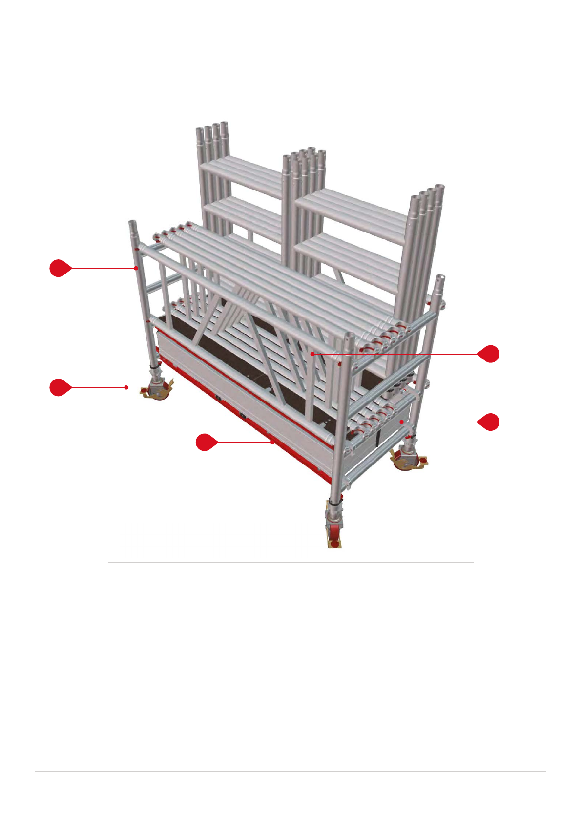
KNOW YOUR MI TOWER+ COMPONENTS
Page 4
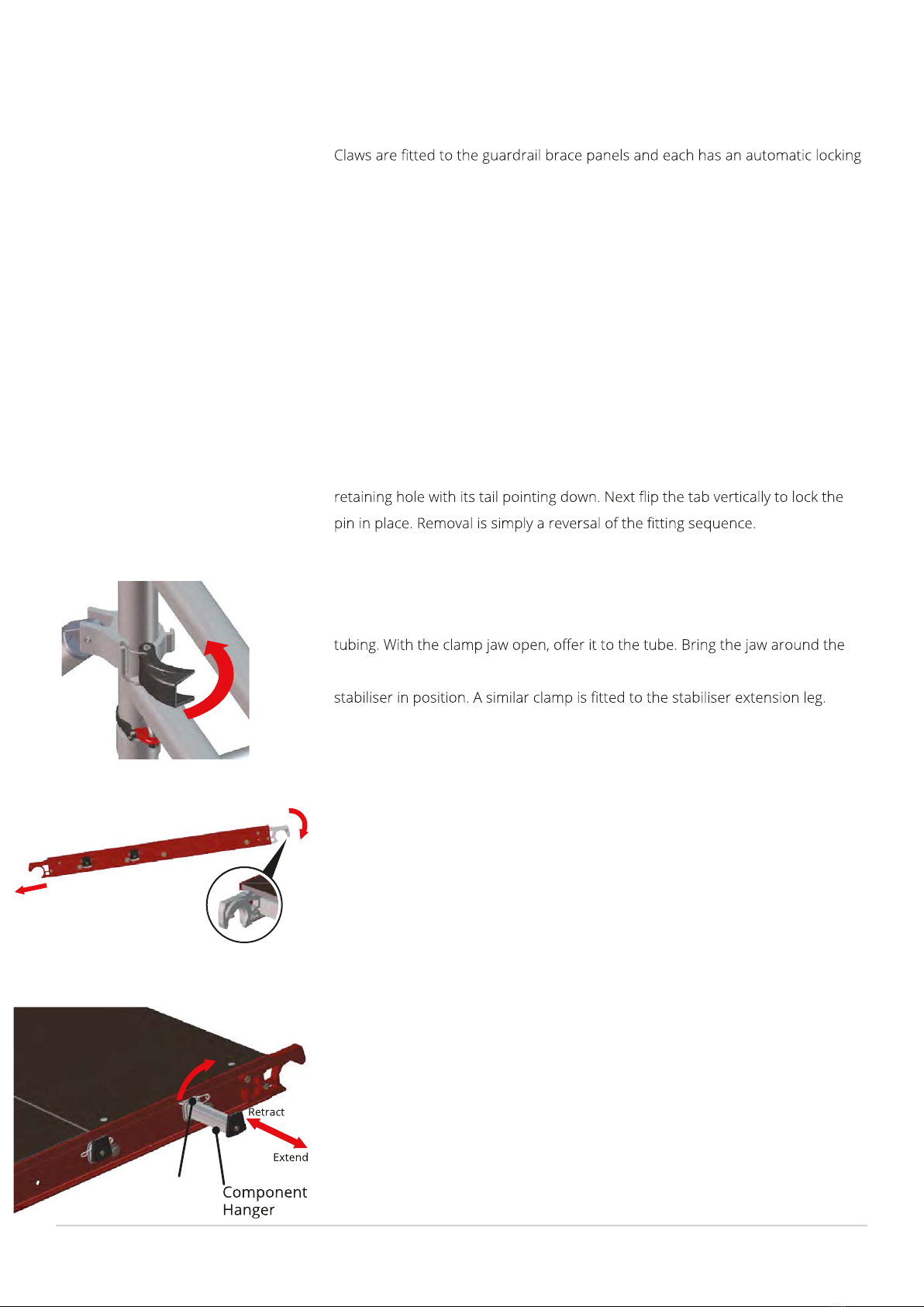
1 GUARDRAIL BRACE PANEL
jaw which is released by simply moving the jaw’s trigger. The claw must only be
attached to the frame with the opening facing outward. Attachment with the
jaw’s opening facing inward will not fully protect the user if lent upon and may
cause serious injury or death. Always ensure that each claw is positively locked in
position before using your tower.
2 FRAME CLIPS
The frame clip’s pin locates into a retaining hole in the frames to lock tower
sections together when placed one on top of the other. The pin is locked in place
by a red tab to ensure that it remains in place. From the disengaged position,
pivot the pin / tab to bring the pin horizontal. Insert the pin fully through the
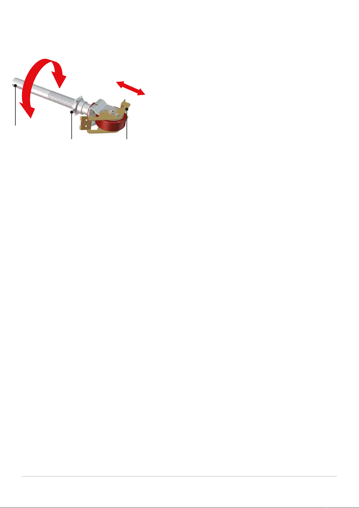
3 STABILISER COUPLER CLAMP
tube and set the buckle on to the hook, then close the clamp arm to lock the
The coupler clamps are used to secure the stabilisers to the tower’s vertical
4 WIND-LOCK CATCH
Disengaged Engaged
Component
Hanger
Retract
Extend
The wind lock catches comprise of a set of auto-engaging hooks at one end
of the platform and a single gravity type catch at the other. The purpose of
these devices is to prevent up-lift of the platforms in windy conditions. To
engage the auto wind lock (AWL) simply tilt the platform at the angle shown
before placing the hooks onto the rung of the end frame. Lower the
opposite end of the platform onto the opposite end frame rung and the
gravity type lock will automatically engage. Simply lift and hold the gravity
lock before tilting the platform to dis-engage the opposite AWL hooks when
removing the platform on tower disassembly.
5 PLATFORM WITH BUILT IN COMPONENT HANGERS
Friction
Clip
To enable one man to erect E products each hatch s fitted th
four component hangers which are stowed (two either side) within the
platform’s frame. The hangers can be extended when needed and retracted
when not.
To extend a hanger simply pull up the friction clip and pull the component
hanger until it stops. To retract the hanger, simply reverse the procedure.