KNOW YOURCOMPONENTS
Page 4
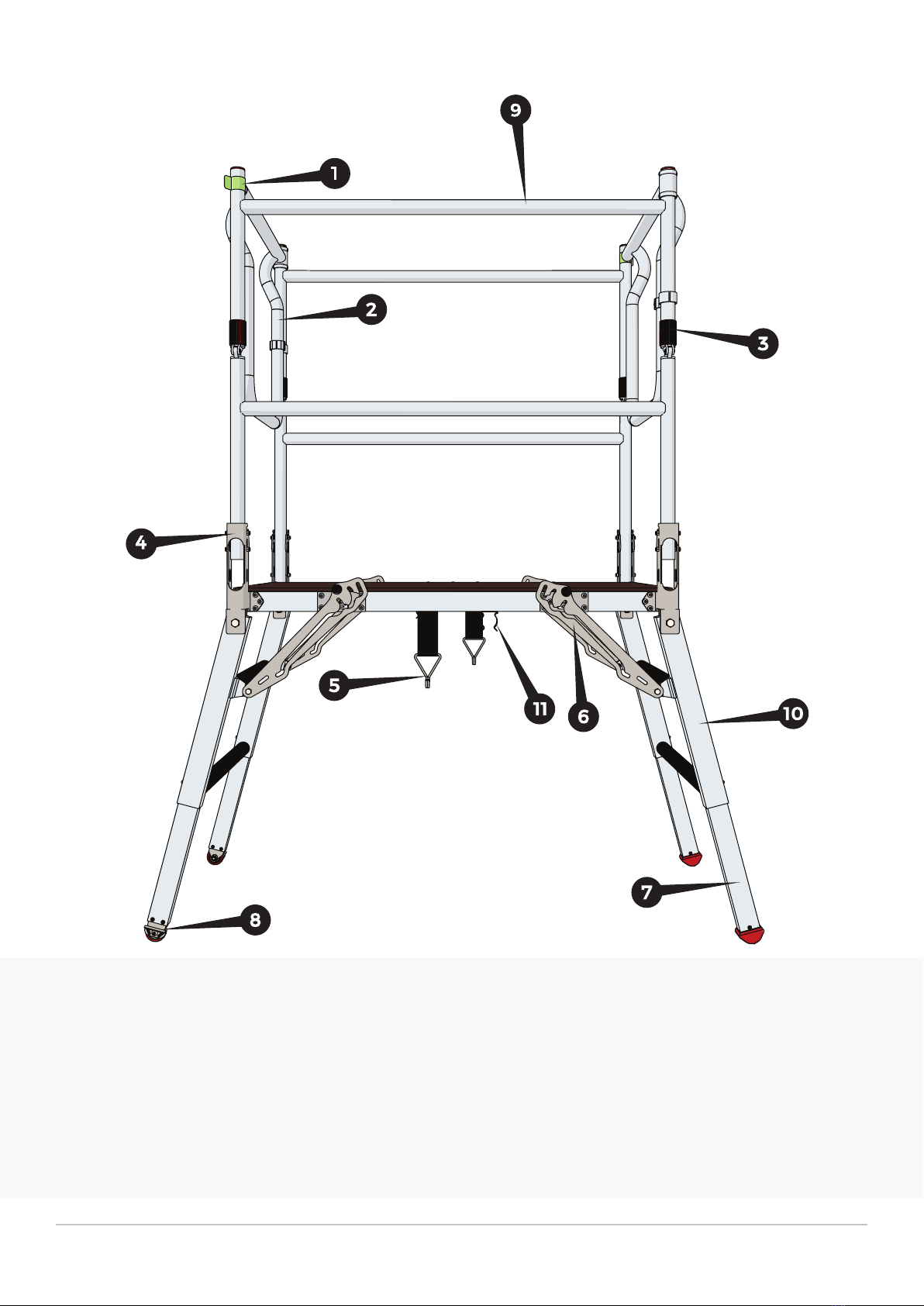
DELTADECK
®
GATE CATCH
The gate catch is a steel spring clip that can be released by pushing on the tab
indicated by the arrow. To close the gate simply pull the gate and ensure the
catch springs over the side guardrail vertical tube gripping it fully.
SIDE GUARDRAIL LOCKING DEVICE
The side guardrail locking device is a gravity operated locking collar used to lock
the side guardrail folding hinge in the upright position. Simply allow the collar
to drop over the hinge when assembling the unit and slide the collar up to
release the hinge when disassembling the unit.
SIDE GUARDRAIL BRACKETS
The side guardrail brackets allow the side guardrails to fold and serve as a locking
device for the lower portion of the side guardrail. The wide slotted bracket is the
side highlighted in green and the narrow slotted bracket highlighted in red. On
assembly the green bracket is opened last and on disassembly closed rst. The
side guardrail must be lifted and rotated simultaneously as shown, during both
assembly and disassembly.
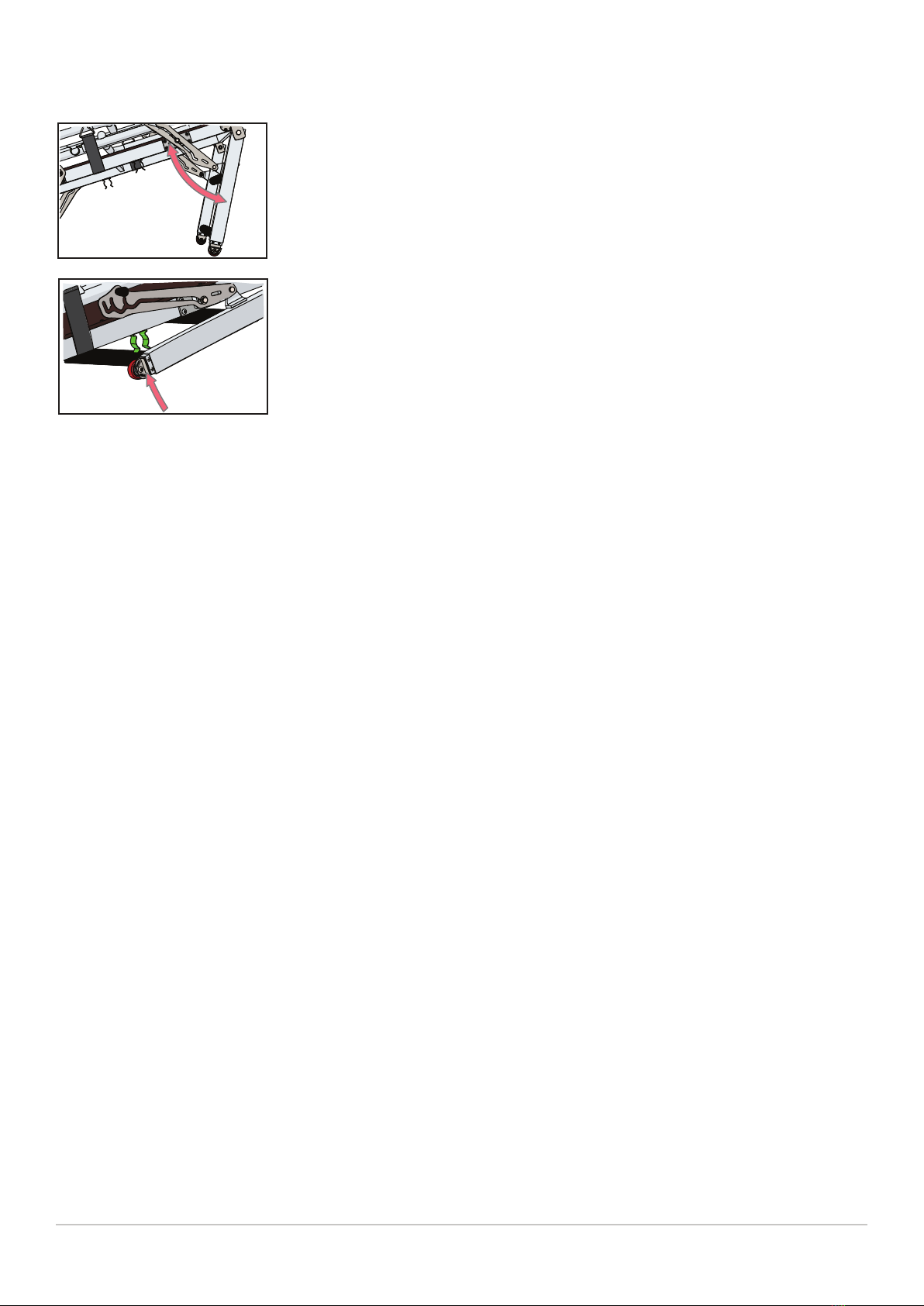
LOCKING CASTOR
The castors allow the unit to be moved smoothly between
workplaces. They must be locked o when the unit is in use and unlocked to
allow the unit to be moved. The foot pedal (Highlighted in yellow) can be rotat-
ed using your foot,to lock or release the brake.
OFF
ON
ADJUSTABLE LEG
The adjustable leg allows further height changes to be made and can be extend-
ed or retracted by simply pushing in the spring locating pin (A) and either
extending or retracting the adjustable leg (B) until the spring pin locates into
one of the three locating holes in the outer leg assembly (C).
A
B
C
The lever (Highlighted in green) allows rotation of the leg assembly (A) and once
locked o in either of the positions (1,2 or 3), it provides height changes to the
unit. Release the leg adjustment lever using the handle (B) and rotate the leg
assembly (A) either way until the lever engages in either position 1,2 or 3.
LEG ADJUSTMENT LEVER
123 A
B
TRANSPORT STRAP
The transport strap holds the folded side guardrail assemblies in place for when
the unit is being transported or stored. Pull the elasticated
transport strap until the metal hook is clear of the guardrail and then either let it
drop over the guardrail for transportation or remove the hook from the guardrail
and release the tension if assembling the unit.