POP UP MI TOWER+ User manual

CONTENTS
CONTENTS
INTRODUCTION
KNOW YOUR MITOWER+
KNOW YOUR MITOWER+’S COMPONENTS
KNOW YOUR KIT LIST AND SPECIFICATIONS
KNOW YOUR STORAGE AND TRANSPORT PACK
SAFETY DOS AND DON’TS - ALWAYS
SAFETY DOS AND DON’TS - NEVER
BEFORE YOU START
1
2
3
4
5
6
7
8
9
GETTING STARTED
MITOWER+ 2M - ASSEMBLY
MITOWER+ 3M - ASSEMBLY
MITOWER+ 4M - ASSEMBLY
MITOWER+ 5M - ASSEMBLY
MITOWER+ 6M - ASSEMBLY
10 POINT PRE-USE SAFETY CHECKLIST
REGISTRATIONS
10
11-12
13-14
15-16
17-18
19-20
21
22
ASSEMBLY GUIDE
FOR MI TOWER+

INTRODUCTION
MiTOWER+ is a safe, versatile and high quality tower. It can be built by ONE PERSON and provides a work
platform for up to TWO PEOPLE. It is designed in accordance with the latest testing and quality standards.
Our priority is to help ensure the safe operation of our products, so please pay particular attention to the safety
tips on pages 7 and 8.
We want you to enjoy the safe and responsible use of MiTOWER+ with the minimum of fuss and this guide is
designed to get you up and running as quickly and as safely as possible.
We recommend that you read this guide prior to assembling and using your MiTOWER+.
Scan this QR code to view the video of MiTOWER+ in operation.
Visit PASMA and HSE for further reference.
www.popupproducts.co.uk/videos/mitower+
Page 2

KNOW YOUR MI TOWER+
Page 3
1
2
3
4 RUNG FRAME
TOE BOARD
TELESCOPIC STABILISER
PARTS LISTING
4
5
6
ADJUSTABLE LEG AND CASTOR
GUARDRAIL BRACE PANEL
HATCH PLATFORM

KNOW YOUR MI TOWER+’S COMPONENTS
Page 4
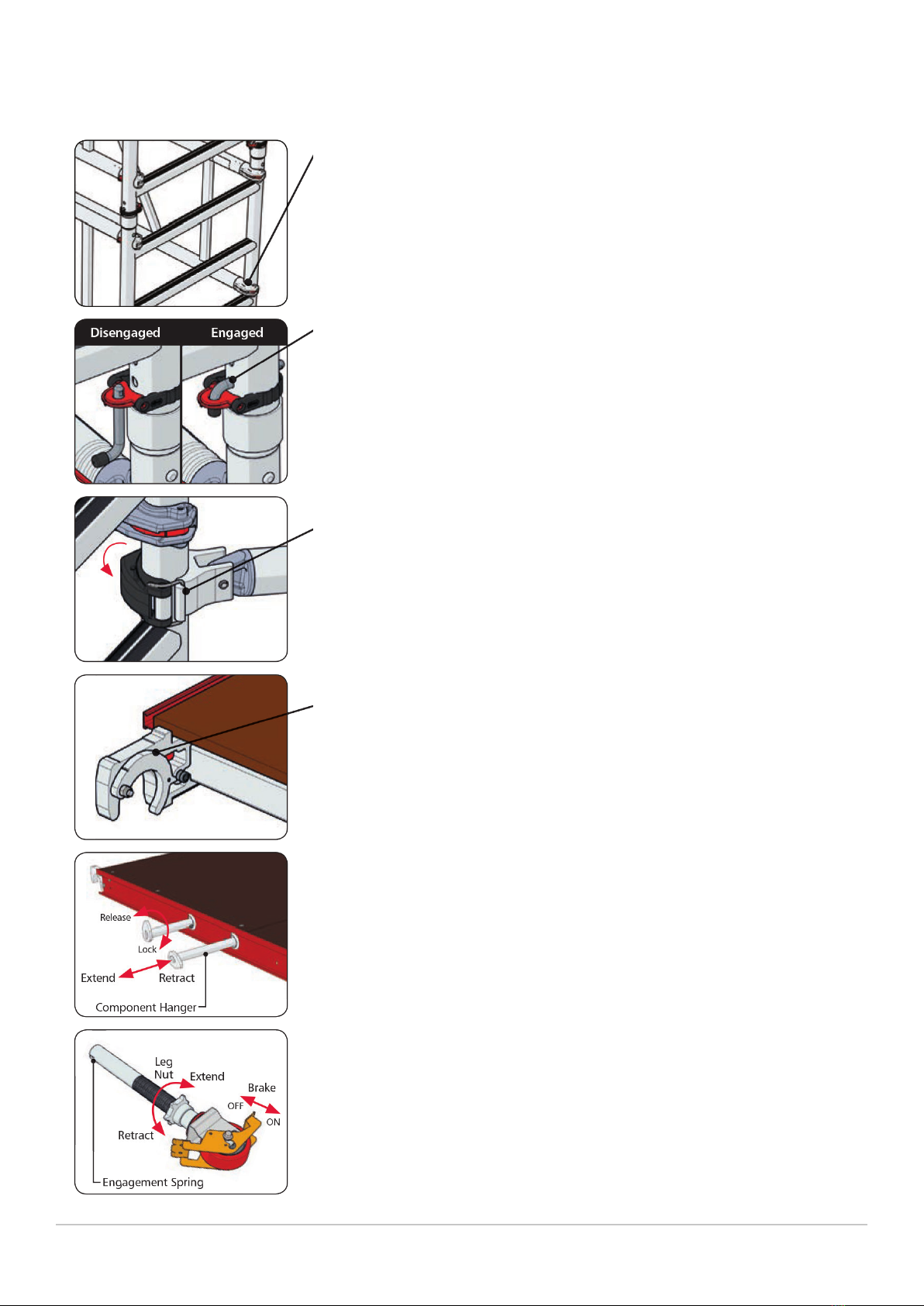
1 GUARDRAIL BRACE PANEL
Claws are tted to the guardrail brace panels and each has an automatic locking
jaw which is released by simply moving the jaw’s trigger. The claw must only be
attached to the frame with the opening facing outward. Attachment with the
jaw’s opening facing inward will not fully protect the user if lent upon and may
cause serious injury or death. Always ensure that each claw is positively locked in
position before using your MiTOWER+.
2 EASY-CLIP FRAME CLIPS
The frame clip’s pin locates into a retaining hole in the frames to lock tower
sections together when placed one on top of the other. The pin is locked in place
by a red tab to ensure that it remains in place. From the disengaged position,
pivot the pin / tab to bring the pin horizontal. Insert the pin fully through the
retaining hole with its tail pointing down. Next ip the tab vertically to lock the
pin in place. Removal is simply a reversal of the tting sequence.
3 EASY-LOCK STABILISER
The coupler clamps are used to secure the stabilisers to MiTOWER+’s vertical
tubing. With the clamp jaw open, oer it to the tube. Bring the jaw around the
tube and set the buckle on to the hook, then close the clamp arm to lock the
stabiliser in position. A similar clamp is tted to the stabiliser extension leg.
4 WIND-LOCK CATCH
The wind-lock catch is a drop down jaw tted to the side of the hatch platform’s
mounting hook and prevents the platform from lifting in windy conditions. It is
attached to the horizontal tube of the frame. To disengage, simply lift and hold
the jaw as you raise the platform clear.
5 PLATFORM WITH BUILT IN EASY-HANG HANGERS
To enable one man to erect MiTOWER+, each hatch platform is tted with four
component hangers which are stowed (two either side) within the platform’s
frame. The hangers can be extended when needed and retracted when not.
To extend and lock a hanger, take a hold of the hanger stop end and pull from
the frame. Once the stop rivet is clear of the slot, turn the hanger 45 degrees
anticlockwise then gently slide back in until it stops. To retract the hanger, simply
reverse the procedure.
6 ADJUSTABLE LEG AND CASTOR
The adjustable leg and castor allows for accurate positioning of your MiTOWER+
in relation to your workplace. The leg can be extended or retracted to allow for
levelling and the brake must be applied to prevent movement.

KNOW YOUR KIT LIST AND SPECIFICATIONS
Page 5
4 RUNG FRAME
TELESCOPIC OUTRIGGER
HATCH PLATFORM
GUARDRAIL BRACE PANEL
220MM ADJUSTABLE LEG
125MM LOCKING CASTOR
TOE BOARD SET
MITOWER+ WEIGHT (KG)
PLATFORM SAFE WORKING LOAD (KG)
GROUND CONDITIONS
3.55
4.35
12.20
4.15
0.85
2.45
6.50
Weight (Unit)
kg
6
4
1
4
4
4
1
87.20
275
2m
qty
8
4
2
6
4
4
1
114.80
275
3m
qty
10
4
2
7
4
4
1
126.05
275
4m
qty
COMPONENT MATRIX AND WEIGHTS
12
4
3
9
4
4
1
153.65
275
5m
qty
14
4
3
10
4
4
1
164.90
275
6m
qty

KNOW YOUR STORAGE AND TRANSPORT PACK
Page 6
TRANSPORT AND STORAGE
For ease of storage and of transportation,
MiTOWER+ has been designed so that all
components can be safely stored within the
tower’s base assembly. See illustration.
Product shown is MiTOWER+ 6m
TROLLEY COMPONENTS
1
2
3
4
5
GUARDRAIL BRACE PANEL X2
TOE BOARD SET
HATCH PLATFORM
ADJUSTABLE LEG AND CASTOR X4
4 RUNG FRAME X2

SAFETY DOS AND DON’TS - ALWAYS
Page 7
ALWAYS Read and understand this guide before you begin assembly.
Ensure that all safety requirements are met and that MiTOWER+ is the correct access solution
for the task you wish to perform.
Ensure that MiTOWER+ is assembled and dismantled by a qualied, competent person.
Cordon o the work area creating a zone with a radius that is 1m greater than the total height
of MiTOWER+.
Wear the correct Personal Protective Equipment for the task being performed. Gloves, steel
toecap boots, a hard hat and suitable clothing must be worn by all persons.
Tie back long hair and remove items of loose jewellery.
Perform a full risk assessment prior to assembling or using MiTOWER+ and abide by your
ndings.
Prevent access to unauthorised persons if you have no ohter option but to leave MiTOWER+
unattended and if this is not possible then MiTOWER+ must be dismantled.
Carry tools and materials safely retained in a tool belt that allows freedom of movement.
Ensure you properly assess the risk/method if tools or materials are hoisted to the platform via
a rope.
Access platforms from within MiTOWER+ and via the 4 rung frames positioned at the platform’s
trap door end. Keep your feet in the middle of the rungs and grip the upper rungs with your
hands.
Erect MiTOWER+ on smooth level ground that is capable of supporting its own weight, the user
and any tools or materials without subsidence.
ALWAYS
ALWAYS
ALWAYS
ALWAYS
ALWAYS
ALWAYS
ALWAYS
ALWAYS
ALWAYS
ALWAYS
ALWAYS

SAFETY DOS AND DON’TS - NEVER
Page 8
NEVER Use MiTOWER+ if you don’t understand something in this guide; please contact the supplier
for advice.
Assemble, use, move or dismantle MiTOWER+ if you are tired or unwell or if you are under the
inuence of alcohol or drugs.
Use MiTOWER+ in adverse weather conditions which may endanger the user.
Use in wind conditions of Beaufort Force 5 and above. Please be aware of the tunnel eect
caused by buildings close to each other.
Assemble or use MiTOWER+ near overhead hazards such as power lines that are within reach
of MiTOWER+ or the user.
Ascend or descend your MiTOWER+ if both hands are not free.
Add banners, notice boards, etc. to MiTOWER+.
Use MiTOWER+ if contaminated by paint, chemicals, etc.
Overload the platforms (see component matrix page 5).
Suspend MiTOWER+ from another structure.
Lean from MiTOWER+ and never apply undue side force.
Stand on the guardrails, toe boards, boxes (or similar) to gain extra height. If the working
height is insucient either construct MiTOWER+ to the required height or use an alternative
method.
Use damaged components in your MiTOWER+ assembly.
NEVER
NEVER
NEVER
NEVER
NEVER
NEVER
NEVER
NEVER
NEVER
NEVER
NEVER
NEVER

BEFORE YOU START
Page 9
PREPARATION
The oor area must be clear of any obstructions including materials and debris. Check that you have all the
components necessary to construct the tower height you require. Check also each component for condition
and correct function. If any part is missing or damaged/not working correctly it must be replaced before
assembling the tower.
3T (THROUGH THE TRAPDOOR) SYSTEM
The 3T method of construction has been developed to reduce the risk of an erector falling from a tower
during construction. The erector must sit on the platform with legs through the hatch and feet on the
frame rungs when attaching guardrail brace panels above the platform. This ensures the erector is always
protected by a set of guardrail brace panels.
TYING IN
You should consider tying in the tower to add to stability, but this may only be carried out by a suitably
trained person.
BALLAST
Where shown in the component list, ballast must be used to stabilise against overturning. Only use solid
materials as ballast (i.e. no loose materials) and position to avoid overloading individual components. Ballast
should be supported by the base of your MiTOWER+ and securely fastened to prevent removal.
ASSEMBLY GUIDE
These instructions must always be made available to the user. If replacement copies are required, please
contact your supplier.
DAMAGED COMPONENTS
Regularly inspect all components for damage. Damaged components must be quarantined so that they
cannot be used. Where safe to do so, the component can be repaired but only by a qualied repairer. If in
doubt contact your supplier for advice.
DISMANTLING YOUR MI TOWER+
MiTOWER+ is easily dismantled by simply reversing the erection procedure. Make sure that the component
hangers are evenly loaded to ensure your MiTOWER remains balanced. You must, however, be protected
by guardrail brace panels when standing on any platform and ensure that you use the 3T method when
removing guardrail brace panels.

GETTING STARTED
Page 10
GETTING STARTED
MiTOWER+ requires only one person to assemble and dismantle it. Your MiTOWER+ is supplied with uniform
1m high 4 rung frames which can be used at any stage of the assembly. During erection, the frames may be
connected together to create 2m high frames which makes assembly both quicker and easier.
STABILISERS POSITIONING
Stabilisers are supplied and must be used for all MiTOWER+ heights.
For maximum eect arrange the stabilisers by positioning at an angle of 45 degrees to give a footprint as close
to square as possible, as shown in Fig. 1.
If the tower is to be positioned against a wall, the stabiliser footprint can be altered as shown in Fig. 2 but only
where the height of the wall is a minimum of two thirds the height of the top working platform.
Ensure that all four stabilisers’ feet are in contact with the ground and that the ground can support the weight
of the tower and stabilisers.
MOVING YOUR MiTOWER+
When your MiTOWER+ needs to be moved a small distance to enable you to continue your task, this can be
achieved provided the stabilisers can remain in pattern and all tools, materials and personnel are removed from
the tower.
You will need to raise the stabilisers so that they are no more than 25mm above the oor and properly locked.
However, if the stabilisers have to be repositioned and this reduces the footprint, your MiTOWER+ must be
reduced in height to 2m.
You must only move MiTOWER+ by manual eort at a slow pace and only after fully assessing the risk. Once
moved, always check MiTOWER+ before using.
If MiTOWER+ is to be moved to a new location, a new level or over rough terrain, it must be fully dismantled and
rebuilt at the new location.
Wall
Fig. 1 Fig. 2

MI TOWER+ 2m - ASSEMBLY
Page 11
STEP 1 FROM TROLLEY
For ease of storage and transportation your MiTOWER+ is designed
so that all the components can be safely stored within the tower’s
base. Start by removing the free-standing components from within the
trolley and stack safely nearby for use. Remove one of the guardrail
brace panels and the hatch platform and store these with the other
components. Level the base as described in Step 2 and move to Step 3.
STEP 1 FROM COMPONENTS
Fully insert the adjustable legs with castors into two frames, turning the
leg’s height adjustment collar to bring each leg 25mm from the lowest
position.
STEP 2
Attach a guardrail brace panel to the vertical tube of one frame with the
upper claw positioned above the fourth rung and with all claws facing
outward. Make sure the claws are correctly locked on to the frame
tube. Now attach the second frame to the guardrail brace panel to
create the base frame assembly. Lock all four castors and using a spirit
level as a guide, adjust each leg to bring the base square and level.
STEP 3
Construct two sets of conjoined frames, these will give you two 2m
sections and will speed up the erection process. Release the frame clips
on one four rung frame and t it on to a second four rung frame. Apply
the frame clips and ensure they are correctly locked. Repeat this with
the second set. Fit one set of conjoined frames to a base frame and
apply the frame clips. Repeat this with the second set.
STEP 4
Next, attach one guardrail brace panel with its lower jaw positioned
above the sixth frame rung. It must be tted on the opposite side to the
rst guardrail brace panel to ensure stability. Ensure all claws are facing
outward and correctly locked on to the frame tube.

MI TOWER+ 2m - ASSEMBLY
Page 12
STEP 5
Stand inside the tower and t a platform on to the eighth rung, making
sure that the wind-lock catches engage.
STEP 6
Fit a stabiliser to each corner of the tower. Position the lower
horizontal stabiliser coupling clamp just above the frame’s second
rung, then secure the top stabiliser coupling clamp just above the
frame’s fth rung. Adjust the stabilisers so that you create as square a
footprint as possible. Adjust each stabiliser’s length so that they are in
contact with the ground. Make sure all coupling clamps are correctly
secured.
STEP 7
Extend and lock the four component hangers located on either side
of the platform. Place two guardrail brace panels on to one set of
hangers, and the toe board set on to the opposite side.
STEP 8
Enter the tower framework and climb the frame rungs until you are
half way through the platform’s trap door. Now manoeuvre yourself
so that you are sitting on the platform, with your legs through the trap
door and your feet on the frame rungs. From this position, you should
take each of the guardrail brace panels, one at a time, and attach so
that the upper jaws are positioned above the uppermost rung.
STEP 9
With both guardrail brace panels in position, you may access the
platform. Unfold the toe board set and position so that it sits on the
outer edge of the platform. Finally, retract all hangers and the tower is
now complete and ready to use.

MI TOWER+ 3m - ASSEMBLY
Page 13
STEP 1
REPLICATE STEPS 1 AND 2 FROM 2M BUILD.
Fit a platform on to the fourth rung, making sure that the wind-lock
catches engage. Next t a single 1m frame to a base frame and apply
the frame clips, then t a second 1m frame to the other base frame
and apply the frame clips.
STEP 2
Next, attach a pair of guardrail brace panels opposite each other with
their upper jaws positioned above the uppermost frame rung. Ensure
all claws are facing outward and correctly locked on to the frame tube.
STEP 3
Fit a stabiliser to each corner of the tower. Position the lower
horizontal stabiliser coupling clamp just above the frame’s second
rung, and then secure the top stabiliser coupling clamp just above the
frame’s fth rung. Adjust the stabilisers so that you create as square a
footprint as possible. Adjust each stabiliser’s length so that they are in
contact with the ground. Make sure all coupling clamps are correctly
secured.
STEP 4
Construct two sets of conjoined frames, giving you two 2m sections.
Take a four rung frame, release the frame clips and t it on to a
second four rung frame. Apply the frame clips ensuring they are
correctly locked and then repeat this process with the second set.
Place the conjoined frames one at each end of the tower ready to
be tted. Extend and lock the four component hangers located on
either side of the rst platform. Place a guardrail brace panel on to a
component hanger on one side of the platform and a second platform
on the other side.

MI TOWER+ 3m - ASSEMBLY
Page 14
STEP 5
Access the rst platform. Fit one set of conjoined frames to each end
of the tower and apply the frame clips. Next, attach the guardrail
brace panel with its lower jaw positioned above the ninth frame rung.
Ensure all claws are facing outward and correctly locked on to the
frame tube. Now carefully t the second platform on to the twelfth
rung, making sure that the wind-lock catches engage. Extend and lock
the four component hangers located on either side of the platform.
STEP 6
Descend the tower and from the ground place two guardrail brace
panels onto the hangers on one side of the higher platform and a toe
board set on the other side.
STEP 7
Access the tower until you are half way through the second platform’s
trap door. Now manoeuvre yourself so that you are sitting on the
platform, with your legs through the trap door and your feet on the
frame rungs. From this position, you should take each of the guardrail
brace panels, one at a time, and attach so that the upper jaws are
positioned above the uppermost rung.
STEP 8
With both guardrail brace panels in position, you may access the
platform. Unfold the toe board set and position so that it sits on the
outer edge of the platform. Finally, retract all hangers and the tower is
now complete and ready to use.

MI TOWER+ 4m - ASSEMBLY
Page 15
STEP 1
REPLICATE STEPS 1 TO 6 FROM 2M BUILD.
Extend and lock the four component hangers located on either
side of the platform. From the ground place three guardrail brace
panels onto the hangers on one side of the platform and two sets of
conjoined four rung frames on the other side.
STEP 2
Access the tower until you are half way through the platform’s trap
door. Now manoeuvre yourself so that you are sitting on the platform,
with your legs through the trap door and your feet on the frame
rungs. From this position, you should take each of the guardrail
brace panels, one at a time, and attach so that the upper jaws are
positioned above the uppermost rung.
STEP 3
Access the rst platform. Fit one set of conjoined frames to each end
of the tower and apply the frame clips. Next, attach the guardrail
brace panel with its lower jaw positioned above the thirteenth frame
rung. Ensure all claws are facing outward and correctly locked on to
the frame tube.
STEP 4
Descend the tower and from the ground place two guardrail brace
panels onto the hangers on one side of the platform and a toe board
set and a platform on the other side.

MiTOWER+ 4m - ASSEMBLY
Page 16
STEP 5
Access the rst platform and carefully t the second platform on to
the sixteenth rung, making sure that the wind-lock catches engage.
Next extend and lock the four component hangers located on either
side of the second platform. Move the two guardrail brace panels
from the hangers on the rst platform on to the the hangers of the
second platform and then repeat the process with the toeboard set
on the other side of the platform.
STEP 6
Access the tower until you are half way through the second platform’s
trap door. Now manoeuvre yourself so that you are sitting on the
platform, with your legs through the trap door and your feet on the
frame rungs. From this position, you should take each of the guardrail
brace panels, one at a time, and attach so that the upper jaws are
positioned above the uppermost rung.
STEP 7
With both guardrail brace panels in position, you may access the
platform. Unfold the toe board set and position so that it sits on the
outer edge of the platform. Finally, retract all hangers and the tower is
now complete and ready to use.

MI TOWER+ 5m - ASSEMBLY
Page 17
STEP 1
REPLICATE STEPS 1 TO 5 FROM 3M BUILD.
Extend and lock the four component hangers located on either
side of the platform. From the ground place three guardrail brace
panels onto the hangers on one side of the platform and two sets of
conjoined four rung frames on the other side.
STEP 2
Access the tower until you are half way through the platform’s trap
door. Now manoeuvre yourself so that you are sitting on the platform,
with your legs through the trap door and your feet on the frame
rungs. From this position, you should take each of the guardrail
brace panels, one at a time, and attach so that the upper jaws are
positioned above the uppermost rung.
STEP 3
Access the second platform and t a set of conjoined frames to each
end of the tower and apply the frame clips. Next, attach the guardrail
brace panel with its lower jaw positioned above the seventeenth
frame rung. Ensure all claws are facing outward and correctly locked
on to the frame tube.
STEP 4
Descend the tower and from the ground place two guardrail brace
panels onto the hangers on one side of the second platform and a toe
board set and a platform on the other side.

MI TOWER+ 5m - ASSEMBLY
Page 18
STEP 5
Access the second platform and carefully t the third platform on to
the twentieth rung, making sure that the wind-lock catches engage.
Next extend and lock the four component hangers located on either
side of the second platform. Move the two guardrail brace panels
from the hangers on the second platform on to the the hangers of the
third platform and then repeat the process with the toeboard set on
the other side of the platform.
STEP 6
Access the tower until you are half way through the third platform’s
trap door. Now manoeuvre yourself so that you are sitting on the
platform, with your legs through the trap door and your feet on the
frame rungs. From this position, you should take each of the guardrail
brace panels, one at a time, and attach so that the upper jaws are
positioned above the uppermost rung.
STEP 7
With both guardrail brace panels in position, you may access the
platform. Unfold the toe board set and position so that they sit on
to the outer edge of the platform. Finally, retract all hangers and the
tower is now complete and ready to use.

MI TOWER+ 6m - ASSEMBLY
Page 19
STEP 1
REPLICATE STEPS 1 TO 3 FROM 4M BUILD.
Extend and lock the four component hangers located on either side of
the platform. From the ground place two guardrail brace panels onto
the hangers on one side of the platform and a platform on the other
side.
STEP 2
Access the rst platform and carefully t the second platform on to
the sixteenth rung, making sure that the wind-lock catches engage.
Next extend and lock the four component hangers located on either
side of the second platform. Move the two guardrail brace panels from
the hangers on the rst platform on to the the hangers of the second
platform.
STEP 3
Access the tower until you are half way through the platform’s trap
door. Now manoeuvre yourself so that you are sitting on the platform,
with your legs through the trap door and your feet on the frame
rungs. From this position, you should take each of the guardrail
brace panels, one at a time, and attach so that the upper jaws are
positioned above the uppermost rung.
STEP 4
Descend the tower and from the ground place three guardrail brace
panels onto the hangers on one side of the rst platform and two sets
of conjoined four rung frames on the other side.
STEP 5
Access the rst platform and move the three guardrail brace panels
from the hangers on the rst platform on to the the hangers of the
second platform. Repeat the process with the two sets of conjoined
four rung frames. Access the second platform and t a set of
conjoined frames to each end of the tower and apply the frame clips.
Next, attach the guardrail brace panel with its lower jaw positioned
above the seventeenth frame rung. Ensure all claws are facing
outward and correctly locked on to the frame tube.
Other manuals for MI TOWER+
1
Table of contents
Other POP UP Construction Equipment manuals
Popular Construction Equipment manuals by other brands

Manitowoc
Manitowoc National Crane NBT50L Series Operator's manual

ABS
ABS ABS-Lock III-B installation manual

Jula
Jula 640-022 operating instructions

Vermeer
Vermeer RTX130 Rental Center Guide

Meec tools
Meec tools 005-242 operating instructions

Meister
Meister MRW1400-2B Translation of the original instructions