Porsche Home Energy Manager Release note

Home Energy Manager
Home Energy Manager
Good to know – Driver’s Manual

07/2022
Porsche, the Porsche Crest, Panamera, Cayenne and
Taycan are registered trademarks of Dr. Ing. h.c. F.
Porsche AG.
Printed in Germany.
Reprinting – even of excerpts – or duplication of any
kind are only permissible with the written authorisa-
tion of Dr. Ing. h.c. F. Porsche AG.
© Dr. Ing. h.c. F. Porsche AG
Porscheplatz 1
70435 Stuttgart
Germany
Installation manual
Always keep this installation manual and hand it over
to the new owner if you sell your charger.
Due to dierent requirements in various countries,
the information in the thumb index tabs of this man-
ual will be dierent. To ensure that you are reading
the thumb index tab that applies to your country,
compare the article number of the charger shown in
the “Technical Data” section with the article number
on the identication plate on the charger.
Further instructions
For information on tting the basic wall mount and
charging dock and for the electrical installation of
the Porsche charger, please refer to the installation
instructions.
Suggestions
Do you have any questions, suggestions or ideas re-
garding your vehicle or this manual?
Please write to us:
Dr. Ing. h.c. F. Porsche AG
Vertrieb Customer Relations
Porscheplatz 1
70435 Stuttgart
Germany
Equipment
Because our vehicles undergo continuous develop-
ment, equipment and specications may not be as
illustrated or described by Porsche in this manual.
Items of equipment are not always according to the
standard scope of delivery or country-specic vehicle
equipment
For more information on retrot equipment, please
contact a qualied specialist workshop. Porsche rec-
ommends a Porsche partner as they have trained
workshop personnel and the necessary parts and
tools.
Because of dierent legal requirements in individual
countries, the equipment in your vehicle may vary
from what is described in this manual. If your Porsche
is tted with any equipment not described in this
manual, your qualied specialist workshop will be
glad to provide information on the correct operation
and care of the items concerned.

1
DANGER
WARNING
CAUTION
NOTICE
About this Owner's Manual
Warning notices and symbols
Various types of Warning notices and symbols are
used in this Driver's Manual.
Serious injury or death
Failure to observe Warning notices in the "Danger"
category will result in serious injury or death.
Possible serious injury or
death
Failure to observe Warning notices in the "Warning"
category can result in serious injury or death.
Possible moderate or mi-
nor injury
Failure to observe Warning notices in the "Caution"
category can result in moderate or minor injuries.
Possible vehicle damage
Failure to observe Warning notices in the "Notice"
category can result in damage to the vehicle.
Information
Additional information is indicated by “Information”.
bConditions that must be met in order to use a
function.
eInstruction that you must follow.
1. If an instruction comprises several steps, these
are numbered.
2. Instructions that you must follow on the cen-
tral display.
gNotice on where you can nd further important
information on a topic.
Further Information
You can access the full Driver's Manual at the follow-
ing web address:
https://tinyurl.com/porsche-e-help

2
Table of contents
Security
Applicable documents. . . . . . . . . . . . . . . . . . . . . . . . . . . . 3
Basic safety principles. . . . . . . . . . . . . . . . . . . . . . . . . . . 3
Proper use. . . . . . . . . . . . . . . . . . . . . . . . . . . . . . . . . . . . . . 3
Qualication of personnel. . . . . . . . . . . . . . . . . . . . . . . . . 4
Notes on installation. . . . . . . . . . . . . . . . . . . . . . . . . . . . . 4
Scope of delivery. . . . . . . . . . . . . . . . . . . . . . . . . . . . . . . . . . 5
Overview
Example of domestic installation. . . . . . . . . . . . . . . . . . 6
Connection diagram. . . . . . . . . . . . . . . . . . . . . . . . . . . . . . 7
Displays and controls. . . . . . . . . . . . . . . . . . . . . . . . . . . . 7
Overview of device connections. . . . . . . . . . . . . . . . . . . 8
Installation and connection
Overview of connectors. . . . . . . . . . . . . . . . . . . . . . . . . 10
Connection to the power grid. . . . . . . . . . . . . . . . . . . . 12
Connection to the building installation. . . . . . . . . . . 14
Establishing a connection to the device. . . . . . . . . . 15
Initial start-up by the customer service. . . . . . . . . . . 17
Establishing a connection to the device. . . . . . . . . . . 18
Logging into the Web Application. . . . . . . . . . . . . . . . 20
Starting Initial Installation. . . . . . . . . . . . . . . . . . . . . . . . 21
Technical Data
Production information. . . . . . . . . . . . . . . . . . . . . . . . . 33
Index. . . . . . . . . . . . . . . . . . . . . . . . . . . . . . . . . . . . . . . . . . . . 34

Security
3
DANGER
Security
Applicable documents
Description Type Information Info
External mains power supply
unit
STEP-PS/ 1AC/24DC/0.75, article number 2868635 www.phoenixcontact.com
Push-on connector 2x1754571, 1x1790108, 1x1790111, 3x1790124,
1x1939439
www.phoenixcontact.com
WiFi antenna HiRO H50284 Wireless 802.11n 2.4GHz WiFi Gain
2dBi OMNI
only 2.4 GHz mains compati-
bility
www.hiroinc.com
Current converter EChun ECS1050-L40P 50 A input; 33.3 mA output www.echun-elc.com
EChun ECS24200-L40G 200A input; 33.3 mA output
EChun ECS36400-L40R 400A input; 33.3 mA output
EChun ECS36600-L40N 600A input; 33.3 mA output
TT 100-SD (LEM) 100 A input; 33.33 mA output www.lem.com
Basic safety principles
Danger to life due to elec-
trical voltage!
There is a risk of injuries due to electric shock and/or
burns, possibly resulting in death.
eDuring all work, make sure at all times that
power to the system is switched o and secured
so it cannot inadvertently be switched on.
eDo not open the housing of the energy manager
under any circumstances.
Proper use
The energy manager is primarily used to safeguard
the electricity supply (overload protection) by pre-
venting the building's main fuse from tripping.
The following count as improper use:
–Carrying out your own modications or additions
to the energy manager
–Any other use of the energy manager not descri-
bed in these instructions
The energy manager is designed as a series instal-
lation device. Installation must be performed under
electrical and information-related conditions.
eIn electrotechnical terms, the energy manager
must be installed in a suitable distribution box.

4
Security
Disclaimer
If the energy manager is damaged due to transport,
storage or handling, repairs are not possible. If the
housing of the energy manager is opened, your war-
ranty will be invalidated. This also applies in the event
of damage due to external factors such as re, high
temperatures, extreme ambient conditions and im-
proper use.
Qualication of personnel
Electrical installation may only be performed by per-
sons with the relevant knowledge of electrical/elec-
tronic equipment (qualied electrician). These per-
sons must be able to provide proof of the required
specialist knowledge for the installation of electrical
systems and their components through a passed ex-
amination.
Improper installation can endanger your own life and
that of others.
Requirements for the qualied electrician performing
the installation:
–Ability to evaluate measurement results
–Knowledge of IP protection classes and their use
–Knowledge about tting electrical installation
material
–Knowledge of the applicable electrical/electronic
and national regulations
–Knowledge of re safety measures and general
and specic safety and accident prevention reg-
ulations
–Ability to select suitable tools, testers and, if
necessary, personal protective equipment, as
well as the electrical installation materials for
ensuring tripping conditions
–Knowledge of the type of power supply network
(TN, IT and TT system) and the resulting connec-
tion conditions (neutral connected to earth in
socket, protective earthing, required additional
measures)
Notes on installation
Electrical installation must be performed in such a
way that:
–Shock protection of the entire electrical installa-
tion is in place at all times, in accordance with
locally applicable regulations.
–The re safety regulations in force at the site are
complied with at all times.
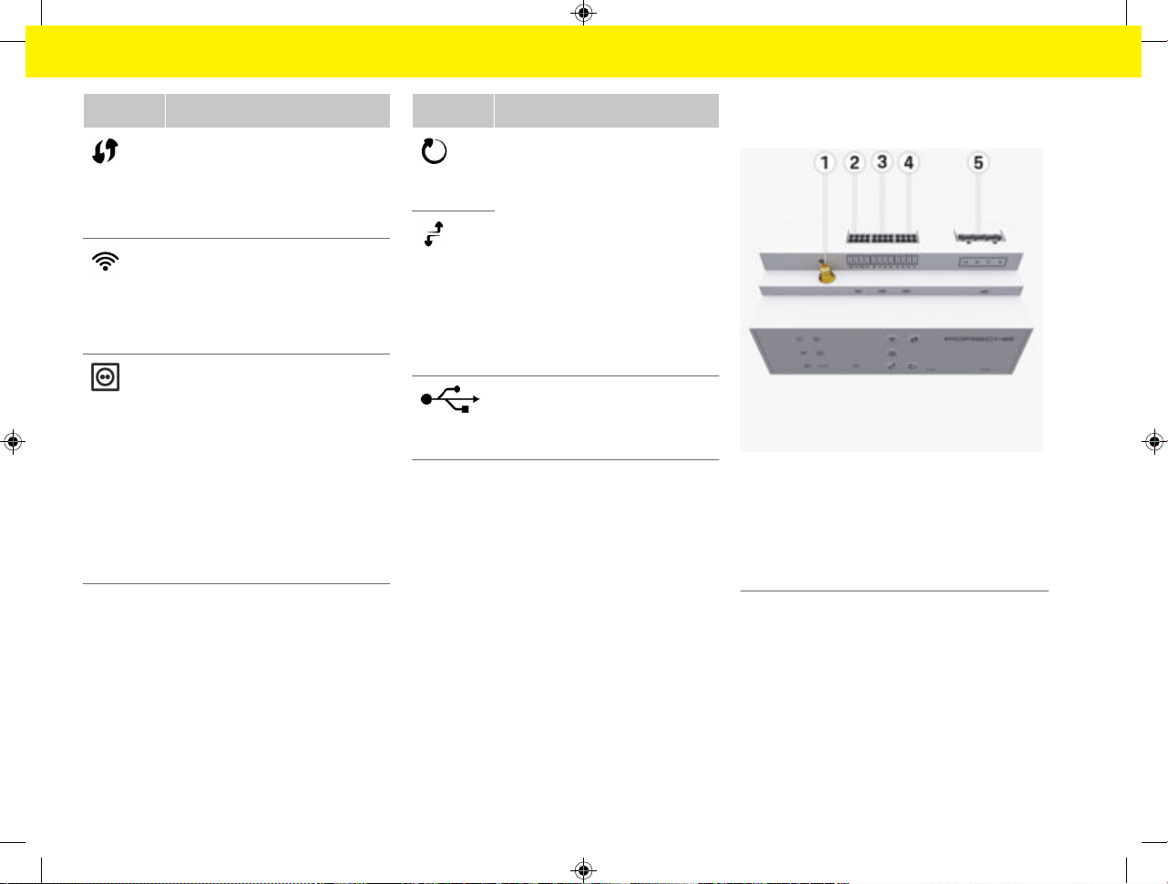
–The controls and displays and USB ports of the
energy manager are accessible to the customer
without restriction and without risk of electric
shock.
–The cables do not exceed the maximum permit-
ted length of 3.0m for each current sensor.
–The inputs for voltage measurement, the exter-
nal power supply and the relays on the energy
manager must be equipped with suitable backup
fuses.
gRefer to chapter "Connection to the power
grid" on page 12.
–The correct length and product-specic bending
radii must be complied with when laying installa-
tion cables.
If the installation environment requires Overvoltage
Category III (OVCIII), the input side of the external
power supply must be equipped with protective cir-
cuity (e.g. a varistor) that conforms to local regula-
tions.
Installation at high altitude
The supply leads of sensors that are installed in elec-
trical facilities at an altitude of over 2,000m or that
must conform to Overvoltage Category III (OVCIII)
due to their installation location require additional
insulation in the form of a shrink-t hose or suita-
ble insulating hose with a breakdown strength of
20kV/mm and minimum wall thickness of 0.4mm
along the entire length of the cable between the
sensor output (housing) and the input terminal on the
energy manager.

Scope of delivery
5
Scope of delivery
Fig.1: Scope of delivery
AEnergy Manager
BExternal mains power supply unit
CWall-mounted distribution box (availability de-
pendent on country)
DWiFi antenna
ELetter containing access data
F3x current converters in version 100 A – or – (de-
pending on the country variant) 2x current con-
verters in version 200 A
GOne set of connectors
Spare parts and accessories
You can order spare parts and additional current con-
verters from your Porsche partner.
Information
The current converters must have a higher rated cur-
rent than the fuse.
eBased on the rated current of the fuse, select the
version with the next highest rated current.
Disposing of the packaging
eTo protect the environment, dispose of packag-
ing materials in accordance with the applicable
environmental protection regulations.
eHand over any residual materials to a specialist
disposal company.

6
Overview
Overview
Example of domestic installation
Fig.2: Example of domestic installation with photovoltaic system and sub-distribution unit
APower supply (1 or 3-phase, here: 1-phase)
BElectricity meter
CCurrent converter (1 current converter per phase)
DDistribution box
EConsumers in the home
FEEBus protocol
GInverter
HPhotovoltaic system
ISub-distribution unit
JConsumers outside the home

Overview
7
NOTICE
Connection diagram
Fig.3: Wiring Diagrams
L1/ L2/ L3 Up to 3 phases
N/PEN Neutral wire
100-240 VAC Input voltage
24 VDC Output voltage
The allocation of phases L1 - L3 may dier from the
illustration g(Fig.3) shown. Please check the phase
assignment at your house connection.
Displays and controls
Fig.4: Displays and controls
Displays Description
Status
On/O
LED lights up green: Energy man-
ager is ready for operation.
Internet
status
LED lights up green: Internet con-
nection established
WiFi status
LED ashes blue. Hotspot mode, no
client connected
LED lights up blue: Hotspot mode,
at least one client connected
LED ashes green: Client mode, no
WiFi connection available
Displays Description
LED lights up green: Client mode,
WiFi connection available
LED lights up or ashes blue: Paral-
lel operation in client mode is possi-
ble.
LED ashes yellow: WiFi connection
via WPS
Status of
Powerline
Communi-
cation
(PLC) net-
work
LED ashes green Searching for PLC
network connection.
LED lights up green: PLC network
connection in place.
LED ashes blue. Activating DHCP.
LED lights up blue: DHCP (for PLC
only) is active and PLC network
connection is in place.
Ethernet
status
LED lights up green: Network con-
nection in place.
RS485/CA
N status
On: LED lights up green during com-
munication (currently not assigned).
Fault sta-
tus
LED ashes or lights up yellow: Fault
present
LED lights up red: Functions restric-
ted

8
Overview
Controls Description
WPS but-
ton
eTo establish a WiFi connection
using the WPS function, briey
press the WPS button (only
network connection as client
possible).
WiFi but-
ton (hot-
spot)
eTo enable WiFi, press the WiFi
button briey.
eTo disable WiFi, press and hold
the WiFi button for more than 1
second.
PLC pairing
button
eTo enable the PLC connection,
briey press the PLC pairing
button.
eTo enable the energy manager
as DHCP server (for PLC con-
nections only), press and hold
the PLC pairing button for more
than 10 seconds.
eFor a PLC connection to a cli-
ent, briey press the PLC pair-
ing button again.
Controls Description
Reset but-
ton
eTo restart the device, press the
Reset button for less than 5
seconds.
eTo reset the passwords, press
and hold the Reset and CTRL
buttons for between 5 and 10
seconds.
eTo reset the device to the fac-
tory settings, press and hold
the Reset and CTRL buttons
for more than 10 seconds. This
overwrites all current settings.
CTRL but-
ton
USB con-
nection
USB connection
eFor information on network connection options,
refer to the installation instructions of the Por-
sche Home Energy Manager on the Porsche
website at the following address:
https://tinyurl.com/porsche-e-help
Overview of device connections
Connections on top of device
Fig.5: Overview of connections on top of device
1WiFi antenna
2/3/4 Current converter (J301),
Current converter (J300),
Current converter (J200)
5Voltage measurement (J400),
Voltage range: 100 V — 240 V (AC)(L-N)

Overview
9
Connections on underside of device
Fig.6: Overview of connections on underside of device
6USB1
7USB2
8ETH 0
9ETH 1
10 RS485/CAN (J1000) (not assigned)
11 Power supply (J102), 24 V (DC)
12 Relay (J900) (not assigned)
13 Relay (J901) (not assigned)
gRefer to chapter "Overview of connectors" on page
10.

10
Installation and connection
Overview of connectors
The overview of device connections ((Fig.5), (Fig.6))
shows the connection position of connectors used for
current converters, voltage measurement, relay con-
tacts and communication. The diagram illustrates the
position of the pins for each type of connector. The
tables show the pin assignment with corresponding
signal.
gRefer to chapter "Overview of device connections"
on page 8.
Connector for current measurement
Information
It is essential to note the connection positions of the
current converters, the type of current converters,
their phase assignment and the rated current of the
phase fuse, as you will be asked for this information
later on when conguring the energy manager (in-
stallation assistant of the web application).
Parameter Value
Push-on connector J200/J300/J301
Manufacturer Phoenix Contact
Socket part number 1786853
Connector part number 1790124
Overview of J200/J300/J301 connectors
The connectors of the current converters (J200,
J300, J301) are identical and can be connected to
any of the connections provided ((Fig.52/3/4)).
Fig.7: Overview of J200/J300/J301
Pi
n
Current converter Code
J200 J300 J301
1 1 5 9 "l",
black
2 1 5 9 "k",
white
3 2 6 10 "l",
black
4 2 6 10 "k",
white
Pi
n
Current converter Code
J200 J300 J301
5 3 7 11 "l",
black
6 3 7 11 "k",
white
7 4 8 12 "l",
black
8 4 8 12 "k",
white
In the case of the LEM current converter cable (100
A), the cable is not white, but black/white.
Information
Pay attention to connector orientation when plugging
in Home Energy Manager! Pins 1, 3, 5, 7 are rounded
and pins 2, 4, 6, 8 are rectangular.
Connector for voltage measurement
Parameter Value
Push-on connector J400
Manufacturer Phoenix Contact
Socket part number 1766369
Connector part number 1939439

Installation and connection
11
Overview of J400 connector
Fig.8: Overview of J400
Pin Signal
1 Neutral wire N
2 Live L1
3 Live L2
4 Live L3
Connector for power supply
Parameter Value
Connector J102
Manufacturer Phoenix Contact
Socket part number 1786837
Connector part number 1790108
Overview of J102 connector
Fig.9: Overview of J102
Pin Signal
1 V (+) 24 V DC ±1 %
2 V (-) 24 V DC ±1 %
3 V (+) 24 V DC ±1 %
4 V (-) 24 V DC ±1 %
Information
Pay attention to connector orientation when plugging
in Home Energy Manager! Pins 1, 3 are rounded and
pins 2, 4 are rectangular.
Connector for relay contact
Parameter Value
Connector J900/J901
Manufacturer Phoenix Contact
Socket part number 1757255
Connector part number 1754571

12
Installation and connection
Overview of J900/J901 connectors
Fig.10: Overview of J900/J901
Pin Signal
1 NO contact
2 COM contact
3 NC contact
Information
The relay connections for the Home-Energy-Manag-
ers are currently deactivated and have no function.
Connector for communication
Parameter Value
Connector J1000
Manufacturer Phoenix Contact
Socket part number 1786840
Connector part number 1790111
Overview of J1000 connector
Fig.11: Overview of J1000
Pin Signal
1 RS485 signal B -
2 RS485 signal A +
3 Earth
4 Earth
5 CAN Low
6 CAN High
Information
Pay attention to connector orientation when plugging
in Home Energy Manager! Pins 1, 3, 5 are rounded
and pins 2, 4, 6 are rectangular.
Connection to the power grid
Installing circuit breakers
Information
Line protection fuses are not included in the scope
of supply and must be installed by a qualied electri-
cian.

Installation and connection
13
NOTICE
The energy manager does not have any internal
fuses. The voltage measurement, external power
supply and relay inputs must therefore be tted with
suitable backup fuses.
–Use of the energy manager requires overcurrent
protection for all supply leads. Make sure you se-
lect fuses with a sensitive trigger characteristic.
–Fuses are selected based on what components
are available in the country of use.
–Use components with the lowest trip current and
shortest trip time.
Preparing the distribution cabinet
For information on the required space for the energy
manager:
gRefer to chapter "Technical Data" on page 32.
eTo install the energy manager inside the distri-
bution cabinet, allow a horizontal pitch (HP) of
11.5 on a DIN rail.
eInstall the mains power supply unit of the energy
manager at a minimum distance of 0.5 HP from
its housing.
eProtect all electrical interfaces from direct/indi-
rect contact.
Fig.12: Preparing the distribution cabinet
AHorizontal pitch 11.5
BHorizontal pitch 9
CHorizontal pitch 0.5
DHorizontal pitch 2
Installation in the distribution cabinet
bThe DIN rail bracket on the housing of the energy
manager has been released.
1. Position the DIN rail bracket at an angle against
the DIN rail in the distribution cabinet.
2. Tilt the housing of the energy manager and lay
evenly on the DIN rail.
3. Fasten the DIN rail bracket to the housing of the
energy manager.
Fig.13: Installation in the distribution cabinet
4. Check that the energy manager is securely en-
gaged on the DIN rail.
Install current converter
Incorrect direction of measurement of the current
converter
Installing the current converter with the incorrect di-
rection of measurement can lead to incorrect results
and malfunctions.
eObserve direction of measurement of the current
converter (Fig. 15, yellow arrows).
Install the current converters for measuring the total
current of the business premises/household in the
relevant main phases downstream of the main fuse.
The energy ows must not yet have been divided into
further sub-circuits.
gRefer to chapter "Overview" on page 6.

14
Installation and connection
NOTICE
eMake sure that all materials that protect against
corrosion are removed from the current con-
verter.
eAdhere to the maximum permitted cable length
of 3.0 m for each current converter.
eSelect an installation location that allows cables
to be routed straight, and pay attention to the di-
rection of measurement (arrow pointing towards
the load) ((Fig.), yellow arrow).
eInsert the installation cable in the current con-
verter and close the converter cap ((Fig.14),
yellow arrow).
eMake sure that the current converter actually has
a higher rated current than the circuit breaker.
eFirst insert the current converter cables in the
connectors, then insert the connectors in the
sockets of the device.
Information
Make a note of the type of current converter, its
connection position in the energy manager, and the
phase (e.g. L1 or L2) to which the current converter
was attached. You will need this information for con-
guring the current converters in the Web Applica-
tion.
If you need to extend the measurement leads, use the
same type of lead if possible.
If the installation environment requires the use of
the optional wall-mounted distribution box, route the
leads into this distribution box via suitable cable
guide systems (empty conduits, cable ducts, etc.).
Fig.14: Installation example of current converter
Routing connecting cables
Before installing any equipment, route the connect-
ing cables inside the distribution cabinet in accord-
ance with local regulations, and protect all electrical
interfaces from contact.
eUse suitable installation cables in accordance
with local regulations.
eCut the installation cables to length to suit the
available space and installation locations.
eMake sure the installation cables comply with
the product-specic bending radii, to prevent
faults with cables and hardware.
Connection to the building installa-
tion
Incorrect phase assignment
Incorrectly assigned phases can lead to incorrect re-
sults and malfunctions.
With a multiphase power grid, make sure that a
phase in the domestic connection matches the phase
at the Porsche charger connection and, if applicable,
the inverter phase of the photovoltaic system. Phase
shis should not exist anywhere, as otherwise the
phase-individual charging functions will not work.
With this installation, you can assign current convert-
ers to power sources and current converter in the
Web Application in the normal phase sequence (e.g.
L1-L2-L3), as for the voltage measurement phases.
Connect all devices to the existing building installa-
tion in accordance with local regulations and stand-
ards.

Installation and connection
15
Charging cable communication with the en-
ergy manager
–The intelligent charging cable features a multi-
phase connection (electrical socket or perma-
nently installed):
eMake sure that the phases of the energy man-
ager and the charging cable match.
–The intelligent charging cable features a single-
phase connection:
eWhen assigning phases in the Web Application,
use the phase to which the intelligent charging
cable is connected.
Connecting an external mains power supply
unit
eFollow the manufacturer's installation instruc-
tions.
gRefer to chapter "Applicable documents" on
page 3.
eConnect the DC output to the energy manager
using the terminal assignment of the connector
for the power supply (J102).
eConnect the mains power supply unit to the en-
ergy manager via cables. These cables must be
prepared by a qualied electrician.
Connecting RS485/CAN communication
Information
The soware (08/2019) does not cover the connec-
tion to RS485/ CAN. For future features, please pay
attention to information on new soware releases.
When connecting the energy manager to the building
installation, there is a risk of inserting the DC power
supply connector (J102) into the RS485/CAN port
by mistake. This can damage the energy manager.
By inserting the 6-pin connector without connecting
cable, included in the scope of supply (J1000), you
will avoid interchanging connectors.
eInsert the connector without connecting cable
into socket J1000 in the housing of the energy
manager.
Connecting relay channels
Information
The soware does not cover the connection to relay
channels. For future features, please pay attention to
information on new soware releases.
The energy manager scope of supply includes a suit-
able connector without connecting cable.
eInsert the connector without connecting cable
into socket J900/J901 in the housing of the
energy manager.
Connecting current and voltage measure-
ment
The current and voltage measurement channels are
connected via several plug connections. The required
connectors are included in the energy manager scope
of supply. If the current converters or voltage meas-
urement leads are not connected, or connected in-
correctly, function will be extremely restricted.
ePay attention to the markings on the device
when connecting current converters and voltage
measurement leads. You will nd a video for sin-
gle-phase installation on the Porsche website at
the following address:
https://tinyurl.com/porsche-e-help
Establishing a connection to the
device
To use the energy manager via the Web Application,
your device (PC, tablet or smartphone) and the en-
ergy manager must be in the home network (via WiFi,
PLC or Ethernet connection).
All the functions of the Web Application can be used
via the internet connection of the home network. The
network connection of the device via an Ethernet
cable is recommended. If there is no home network
available at the place of use, your device can log in to
the energy manager directly via its WiFi hotspot.
eThe Home Energy Manager operates exclusively
in the 2.4 GHz network (see gP.32)
eSelect the connection type suitable for the pre-
vailing signal strength and availability.
Connecting the WiFi antenna
You can connect a WiFi antenna to boost the WiFi
signal.

16
Installation and connection
1. Connect the WiFi antenna to the energy man-
ager via the plug-in/screw connections provided
for this purpose.
2. Secure the WiFi antenna to the outside of the
metal distribution cabinet by its magnetic base
(if the WiFi antenna is inside the metal distribu-
tion cabinet, it cannot receive a signal). Make
sure that the WiFi antenna is positioned cor-
rectly (e.g. at an angle of 90° to the router).
Checking the signal quality of the PLC net-
work
Information
The soware and Ethernet PLC converter described
in this section are not included in the scope of supply.
To check the connection quality of the PLC network,
you can determine the PLC data transfer rate through
the domestic electrical system using soware and
Ethernet PLC converters. For this purpose, connect
the converters to the mains supply at the installation
locations. Select the installation locations of the en-
ergy manager and the current consumers with PLC
functionality (such as the Porsche charger) as instal-
lation locations for this. The real data transfer rate
between the installation locations can be visually dis-
played using powerline soware. Data transfer rates
of 9 Mbit or more are sucient.
If electrical installations are not ideal, PLC commu-
nication may be impossible or so weak as to pre-
vent stable EEBus communication with the Porsche
charger.
eIn this case, select an alternative communica-
tions interface (Ethernet or WiFi).

Initial start-up by the customer service
17
Initial start-up by the cus-
tomer service
Aer the energy manager has been installed, the de-
vice must be congured for initial start-up.
Information
Initial start-up may only be carried out by a qualied
electrician.
During initial start-up, a setup wizard in the Web
Application guides through the necessary settings
(e.g. connections, user prole, optimised charging).
Some of the settings entered here, such as those
involving the system and maintenance, can also be
changed later on by the home user. Within the instal-
lation wizard, the electrician must carry out the home
installation. This includes the conguration of the
current converters and the addition of EEBus devices.
Aer this, the energy manager is ready for operation.
Requirements for initial start-up
Have the following information to hand for setting up
the energy manager:
–Letter containing access data for logging into the
Web Application
–Private data such as the access data of your
home network and the access data of the user
prole (to link it with your Porsche ID) do not
need to be specied.
–Information on electricity taris/prices and any
feed-in remuneration
Information
Only the letter containing access data is required for
partial commissioning. All other settings can also be
made later.
The following browsers are supported by the Web
Application:
–Google Chrome version 57 or later (recommen-
ded)
–Mozilla Firefox version 52 or later (recommen-
ded)
–Microso Internet Explorer version 11 or later
–Microso Edge (recommended)
–Apple Safari version 10 or later
eThe detailed description of the installation assis-
tant with all the steps can be found in the on-
line version of the installation instructions on the
Porsche website at the following address:
https://tinyurl.com/porsche-e-help

18
Establishing a connection to the device
Establishing a connection to
the device
To enable access to the Web Application of the en-
ergy manager, a connection must be established be-
tween your device (PC, tablet or smartphone) and the
energy manager. For an overview of all connection
options, gRefer to chapter "5. Selecting a network
connection" on page 22.
eSelect the connection type suitable for the pre-
vailing signal strength and availability.
Redirecting to Web Application
Information
Depending on which browser you are using, the Web
Application may not open immediately. Instead, a no-
tice regarding the browser's security settings may be
displayed rst.
1. In the browser warning message that appears,
select Advanced.
2. In the next dialogue box, select Add exception.
🡆The SSL certicate is conrmed and the
Web Application opens.
WiFi
There are two options for a WiFi connection:
–hotspot:
The energy manager has a wireless access point
(hotspot), which is password-protected and re-
quires manual login. A WiFi-capable end device
can connect to the hotspot and then access the
Web Application of the energy manager.
–WiFi network via WPS function:
The energy manager can be paired with an exist-
ing home network, e.g.network router, using the
WPS function, without entering a password.
Web Application Opening via hotspot
bThe energy manager is switched on. The energy
manager automatically enables its WiFi hotspot.
1. If WiFi status does not ash or light up blue,
press the WiFi button on the energy manager.
2. On your device, press the network or WiFi icon
on the taskbar or notication panel.
3. Select your WiFi network from the list. The name
of the WiFi network is the same as the SSID in
the letter containing access data, and is shown
as HEM-#######.
4. Select button Connect.
5. Enter the security code. The security code is
shown as WiFi PSK in the letter containing your
access data.
🡆The connection to the WiFi network is es-
tablished.
Note: In the Windows 10 operating system,
you are rst asked to enter the router PIN.
Select the link Establish connection with
PLC security code and then enter the key.
6. Open your browser.
7. Enter the IP address of the energy manager in
the address bar of your browser: 192.168.9.11
– or –
Enter the DNS address of the energy manager
in the address bar of your browser: https://por-
sche.hem
gRefer to the Porsche Home Energy Manager Oper-
ating Manual.
Open Web Application via WiFi (WPS func-
tion)
1. Press the WPS button on the network router.
2. Within 2 minutes, press the WPS button on the
energy manager.
3. Select the appropriate network in the router set-
tings and nd out the IP address of the energy
manager.
4. Enter the IP address of the energy manager in
the address bar of your browser.
gRefer to the Porsche Home Energy Manager Oper-
ating Manual.
Information
Some routers oer the option of accessing the Web
Application using the host name Porsche-HEM (e.g.
via https://porsche-hem/).
Ethernet
1. Connect the Ethernet cable to the energy man-
ager (port ETH0).
2. Select the appropriate network in the router set-
tings and nd out the IP address of the energy
manager.
3. Enter the IP address of the energy manager in
the address bar of your browser.
PLC client
The energy manager can be integrated in a PLC net-
work as a client.
Note: For this, you will need a PLC modem with
HomePlug standard (not included in the scope of
delivery).
Other manuals for Home Energy Manager
9
Table of contents
Other Porsche Automobile Batteries Charger manuals